1
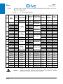
x 20130630 x
iDrive
MULTIFUNCTION AC DRIVE
English
BASIC
USER MANUAL
Issued on 06/30/13
R. 05
x This manual is integrant and essential to the product. Carefully read the instructions contained herein as they
provide important hints for use and maintenance safety.
x This device is to be used only for the purposes it has been designed for. Other uses should be considered
improper and dangerous. The manufacturer is not responsible for possible damages caused by improper, erroneous
and irrational uses.
x Lönne Scandinavia AS is responsible for the device in its original setting.
x Any changes to the structure or operating cycle of the device must be performed or authorized by Lönne
Scandinavia AS
x Lönne Scandinavia AS assumes no responsibility for the consequences resulting by the use of non-original spareparts.
x Lönne Scandinavia AS reserves the right to make any technical changes to this manual and to the device without
prior notice. If printing errors or similar are detected, the corrections will be included in the new releases of the
manual.
x The information contained herein is the property of Lönne Scandinavia AS, and cannot be reproduced. Lönne
Scandinavia AS enforces its rights on the drawings and catalogues according to the law.
Lönne Scandinavia AS
Liamyrane 12 – N-5132 Nyborg, Norway
Tel. +47 55 39 10 00 – Fax +47 55 39 11 00
www.lonne.com [email protected]
BASIC
USER MANUAL
iDrive
0. STARTUP
NOTE
This manual covers basic installations of the iiDrive. For more details, please refer to
the standard iDrive’s Installation Instructions manual.
NOTE
iDrive is factory set with the IFD control algorithm (V/f) allowing performing the first
startup of the equipment. The default functions are given in this section, particularly
in step 5): Start up.
1) Inspection:
Check if the size of the iDrive is greater than or equal to the size of the connected motor according to
the drive nameplate. See the Delivery Check section.
2) Installation
and wiring:
The IP rating of the iDrive is given in the Installing the Equipment section. Ensure that sufficient
ventilation is provided to the drive. More details are given in the standard iDrive Installation
Instructions manual.
3) Power on:
Power on the drive; check if the keypad turns on.
For an easier startup of the iDrive, you can activate the Start-Up Menu. The Start-Up Menu is a
wizard allowing programming the main parameters for the connected motor.
The Start-Up Menu is displayed when the iDrive is first started. The Start-Up Menu can be reactivated
at any time. To do so, set P265 in “Start Up” mode:
[ I DP ]
i D r i v e
S T A R T - UP ME N U
P r e s s ENTER
t o s t a r t
Press Enter to enter the wizard. Before entering the control parameters, you are asked to choose a
dialogue language:
P 2 6 3
L a n g u a g e
o @ @@ @ @ @ @@@@@@@@@
4) Parameter
setting:
Then you are asked to choose the display mode of the Start Up Menu:
Whe n
d o e s
t he
S t a r t - U p Me n u
a c t i v a t e ?
o@@@@@@@@@@@@@@@
Choose one of the following:
1
2
3
4
2/34
:
:
:
:
EV E
ON L
N EX
NE V
RY S T AR T - UP
Y N OW
T
S T AR T - UP
ER
BASIC
USER MANUAL
iDrive
If you select “EVERY START-UP”, the wizard appears whenever the iDrive is powered on;
if you select “ONLY NOW”, you can scroll through the menu and the wizard is disabled as soon as
you quit the menu;
if you select “NEXT START-UP”, the menu is displayed only the next time the iDrive is started up;
if you select “NEVER”, the Start-Up menu is disabled.
Parameters included in the Start-Up menu:
Parameter
C008
Description
Rated mains voltage
Visibility
C010
Type of control algorithm
C012
Speed feedback from encoder
[only if FOC is active]
C013
Type of V/f pattern
[only if IFD is active]
C015
Rated motor frequency
C016
Rated motor rpm
C017
Rated motor power
C018
Rated motor current
C019
Rated motor voltage
C021
No-load current of the motor
C028
Min. motor speed
C029
Max. motor speed
C034
Voltage preboost
P009
Acceleration ramp time
[only if FOC is active]
[only if IFD is active]
P010
Deceleration ramp time
C043
Current limit while accelerating
[only if IFD is active]
C044
Current limit at constant rpm
[only if IFD is active]
C045
Current limit while decelerating
[only if IFD is active]
C048
Torque limit
[only if VTC/FOC are active]
C189
Encoder operating mode
[only if FOC is active]
C190
Encoder A pls/rev
[only if FOC is active]
C191
Encoder B pls/rev
[only if FOC is active]
I073
Autotuning selection
[only if VTC/FOC are active]
I074
Motor tuning selection
[only if VTC/FOC are active]
C265
Motor thermal protection
C267
Motor thermal time constant
[only if protection is active]
After setting the last parameter and moving the cursor forward, the following page will appear:
P
t
D
t
r e s s
U P A R R OW
o
qu i t
OWN A R R OW
o
c o n t i n u e
Press to quit the Start-up menu. The default page of the system will be displayed.
3/34
BASIC
USER MANUAL
iDrive
Terminal Control:
i)
Activate the ENABLE input (terminal 15).
ii) Activate the START input (terminal 14).
iii) Send speed reference to REF: 0-10V (terminals 1,
2 & 3)
REFERENCE
INPUT
0 -: 10 V
2 ÷ 10kohm
or
Send speed reference to AIN1: 4-20mA (terminals
5 & 6). This requires Source Selection input on
MDI6 to be active (terminal 19).
4 ÷ 20 mA
ANALOG
INPUT
4 -: 20 mA
The RUN LED and REF LED will be lit and the motor
will start. Make sure that the motor is rotating in the
correct direction.
5) Startup:
If not, operate on terminal MDI5 (terminal 18)
(CW/CCW) or open the ENABLE and START
terminals. Shut off the drive, wait at least 20 minutes
and swap two of the motor phases.
Keypad Control:
i)
Activate the ENABLE input (terminal 15).
ii) Press the
keypad.
LOCAL/REMOTE
START (MDI1)
ENABLE (MDI2)
button
RESET (P/B) (MDI3)
on
the
iii) The L-CMD and L-REF LEDs will be lit.
iv) Press the START button.
v) Hold the Up button to increase the speed
reference.
MULTISPEED 0 (MDI4)
MULTISPEED 1 (MDI5)
SOURCE SELECTION (MDI6)
LOCAL / REMOTE (P/B) (MDI7)
Cw / CCW (MDI8)
The RUN LED and REF LED will come on and the
motor will start. Make sure that the motor is rotating in
the correct direction.
If not, press the FWD/REV button or press STOP.
Shut off the drive, wait at least 20 minutes and swap two of the motor phases.
6) Possible
failures:
If no failure occurred, go to the next step. Otherwise, check the drive connections paying particular
attention to supply voltages, DC link and input reference.
Also check if alarm messages are displayed. In the MEASURES MENU, check values in the Fault List for
the reference speed (M000), the supply voltage to the drive (M030), the DC link voltage (M029), and the
condition of control terminals (M033). Check to see if these readouts match with the measured values.
7) Additional
parameter
alterations:
In BASIC user level, adjustments can be made to a limited number of parameters. The iDrive has a
wide range of functions; to access these function, set the user level to ADVANCED or
ENGINEERING by adjusting parameter P001 accordingly (refer to iDrive iDrive’s Programming
Instructions manual).
8) Reset:
If an alarm trips, find the cause responsible for the alarm and reset the equipment. Enable MDI3
(terminal 16) or press the RESET key on the display/keypad.
4/34
BASIC
USER MANUAL
iDrive
1. TABLE OF CONTENTS
1.1.
Chapters
0.
1.
STARTUP .................................................................................................................................................................. 2
TABLE OF CONTENTS............................................................................................................................................. 5
1.1.
Chapters .......................................................................................................................................................... 5
1.2.
Figures ............................................................................................................................................................. 5
1.3.
Tables .............................................................................................................................................................. 5
1.4.
How to Use this Manual ................................................................................................................................... 6
1.4.1. Overview ..................................................................................................................................................... 6
2.
HARDWARE DESCRIPTION AND INSTALLATION ................................................................................................. 7
2.1.
Caution Statements.......................................................................................................................................... 7
2.2.
Delivery Check ................................................................................................................................................. 9
2.2.1. Nameplate ................................................................................................................................................. 10
2.3.
Installing the Equipment ................................................................................................................................. 10
2.3.1. Environmental Requirements for the Equipment Installation, Storage and Transport ............................... 11
2.3.2. Power Terminals / Bars ............................................................................................................................. 12
2.3.3. Connection Bars for S60 Inverters ............................................................................................................ 15
2.3.4. Cross-sections of the Power Cables and Sizes of the Safety Devices ...................................................... 16
2.3.4.1.
2T Voltage Class ............................................................................................................................. 16
2.3.4.2.
4T Voltage Class ............................................................................................................................. 17
2.3.4.1.
5T and 6T Voltage Classes.............................................................................................................. 18
2.3.5. Inverter and Motor Earth Connection ........................................................................................................ 19
3.
USING THE DISPLAY/KEYPAD.............................................................................................................................. 20
3.1.
Overview ........................................................................................................................................................ 20
3.2.
Menu Tree ...................................................................................................................................................... 20
3.3.
Navigation ...................................................................................................................................................... 21
3.4.
Function Keys ................................................................................................................................................ 22
3.5.
Indicator LEDs in the Display/Keypad ............................................................................................................ 23
4.
WIRING ................................................................................................................................................................... 24
4.1.
Wiring Diagram .............................................................................................................................................. 24
5.
ALARMS AND WARNINGS ..................................................................................................................................... 26
5.1.
What Happens when a Protective Device Trips ............................................................................................. 26
5.2.
What To Do when an Alarm Trips .................................................................................................................. 27
5.3.
Alarm Code List.............................................................................................................................................. 28
5.4.
Warnings ........................................................................................................................................................ 32
5.5.
State List ........................................................................................................................................................ 34
1.2.
Figures
Figure 1: Nameplate of the iDrive. .................................................................................................................................... 10
Figure 2: Connection bars in S41-S42-S51-S52 ............................................................................................................... 14
Figure 3: S60 Connection bars.......................................................................................................................................... 15
Figure 4: Menu Tree. ......................................................................................................................................................... 20
Figure 6: Wiring Diagram. ................................................................................................................................................. 24
1.3.
Tables
Table 1: Alarm Code List. .................................................................................................................................................. 31
Table 2: Warning list. ........................................................................................................................................................ 33
Table 3: State List. ............................................................................................................................................................ 34
5/34
BASIC
USER MANUAL
iDrive
1.4
4.
1.4.1.
Ho w to Us
se this M
Manual
O VER
RVIEW
This User Ma
anual (Basic User
U
Manual) provides inforrmation requirred to setup an
nd monitor thee drives of the
e iDrive seriess
manufactured
d by Elettronicca Santerno when
w
used in th
he Basic mode.
The section concerning th
he hardware description a nd installation
n covers basic wiring only.. Refer to the
e Installation
n
s manual to insstall additional options and/o
or to configure
e analogue/dig
gital inputs annd outputs.
Instructions
wn parameter set
s and preseet I/O settings
s. If additionall
The iDrive iss delivered in Basic mode, which provid es a cut dow
adjustment iss required, thiss may be achieved by settin
ng the drive to
o Advanced orr Engineering uusing parame
eter P001 (see
e
the PASSWO
ORD AND USER LEVEL ME
ENU in the Prrogramming Instructions
I
manual.
m
Setup/monito
oring may be obtained
o
using
g one or both o
of the followin
ng options:
1)
Disp
play/keypad unit;
2)
Seriial link through
h RS485 stand
dard port or E
ES822 optional board.
For the instrructions on ho
ow to use and
d remote the display/keypa
ad unit, please refer to thee Installation Instructions
s
manual.
Any inform
mation sent to
o/from the drive through th
he display/keyypad unit may
y be obtained
d
also via serial link u sing the Rem
moteDrive so
oftware appliccation provide
ed by Lönne
e
via AS.
Scandinav
The Rem
moteDrive allow
ws the follow
wing functions: image acquuisition, keypa
ad simulation,,
oscillosco
ope functions a
and multifuncttion tester, tab
ble compiler inncluding opera
ation data log,,
parameter setup and d
data reception
n-transmission
n-storage from
m and to a ca
alculator, scan
n
f the autom
matic detection
n of the connected drives (up to 247 drives may be
e
function for
connected
d).
When used in
n Advanced or
o Engineering mode, many additional fun
nctions are ava
ailable. Thesee include the fo
ollowing:
x
x
x
x
x
x
x
x
x
x
x
x
x
x
x
x
x
x
x
x
x
x
x
x
Cusstomisation of Keypad navig
gation.
Cusstomisation of standard mon
nitoring valuess.
Sele
ection of up to
o 4 acceleratio
on and decelerration ramps.
Cusstomisation an
nd scaling of analog input sig
gnals.
Sele
ection of up to
o 15 preset spe
eeds.
Con
nfiguration of 3 prohibit spee
eds.
Utilisation of a speed variation function.
ning of VTC an
nd FOC algoritthms.
Tun
Cusstomisation of analog outputt signals.
Allocation of interrnal timer func
ctions to digita l I/O.
PID activation and
d tuning.
Con
nfiguration of Digital
D
output comparator
c
an
nd logic functio
ons.
Masster/slave operation with torrque control.
Adju
ustment of currrent and torqu
ue limits.
Cusstomisation of digital inputs.
Settting of control source for sta
art and speed commands.
Con
nfiguration of a connected encoder.
DC braking.
namic braking..
Dyn
Spe
eed Search fun
nction.
Auto
oreset.
Mottor thermal mo
odelling and th
hermistor alloccation.
Crane control functions.
Seriial and Fieldbu
us communica
ation.
If any of the above functio
ons is required
d, use parametter P001 to ac
ccess the Advanced or Eng ineering settin
ngs.
6/34
BASIC
USER MANUAL
iDrive
2. HARDWARE DESCRIPTION AND INSTALLATION
2.1.
Caution Statements
SYMBOLS:
DANGER
Indicates operating procedures that, if not correctly performed, may cause serious injury
or death due to electrical shock.
CAUTION
Indicates operating procedures that, if not carried out, may cause serious equipment
failure.
NOTE
Indicates important hints concerning the equipment operation.
SAFETY STATEMENTS TO FOLLOW WHEN INSTALLING AND OPERATING THE EQUIPMENT:
NOTE
1.
2.
Always read this instruction manual before starting the equipment.
The ground connection of the motor casing should follow a separate path to avoid
possible interferences.
1.
ALWAYS PROVIDE PROPER GROUNDING OF THE MOTOR CASING AND THE
DRIVE FRAME.
If a differential relay against electric shocks is intended to be used, this must be a
“B-type” differential relay.
The drive may generate an output frequency up to 1000 Hz; this may cause a motor
rotation speed up to 20 (twenty) times the rated motor speed (for 50Hz motors):
never use the motor at higher speed than the max. allowable speed stated on the
motor nameplate.
ELECTRICAL SHOCK HAZARD – Never touch the drive electrical parts when the
drive is on; always wait at least 20 minutes after switching off the drive before
operating on the drive.
Never perform any operation on the motor when the drive is on.
Do not perform electrical connections on the motor or the drive if the drive is on.
Electrical shock hazard exists on output terminals (U,V,W) and resistive braking
module terminals (+, –, B) even when the drive is disabled. Wait at least 20 minutes
after switching off the drive before operating on the electrical connection of the motor
or the drive.
MECHANICAL MOTION – The drive determines mechanical motion. It is the
operator's responsibility to ensure that this does not give rise to any dangerous
situation.
EXPLOSION AND FIRE – Explosion and fire hazard exists if the equipment is
installed in presence of flammable fumes. Do not install the drive in places exposed
to explosion and fire hazard, even if the motor is installed there.
2.
3.
4.
DANGER
5.
6.
7.
8.
7/34
BASIC
USER MANUAL
iDrive
1.
2.
3.
4.
5.
6.
7.
8.
CAUTION
9.
10.
11.
12.
13.
14.
15.
8/34
Do not connect supply voltages exceeding the equipment rated voltage to avoid
damaging the internal circuits.
If the drive is installed in environments exposed to flammable and/or explosive
substances (AD zones according to IEC 64-2 standards), please refer to IEC 64-2,
EN 60079-10 and related standards.
Do not connect the equipment power supply to the output terminals (U,V,W), to the
resistive braking module terminals (+, -, B) or to the control terminals. The
equipment power supply must be connected only to terminals R,S,T.
Do not short-circuit terminals (+) and (-) and terminals (+) and (B); do not connect
any braking resistors with lower ratings than the required ratings given in the
Installation Instructions manual.
Do not start or stop the connected motor using a contactor over the inverter power
supply.
Do not install any contactor between the inverter and the motor. Do not connect
any power factor correction capacitor to the motor.
Operate the inverter only if a proper grounding is provided.
If an alarm trips, a comprehensive review of the ALARMS AND WARNINGS
section is recommended; restart the equipment only after removing the cause
responsible for the alarm trip.
Do not perform any insulation test between the power terminals or the control
terminals.
Make sure that the fastening screws of the control terminal board and the power
terminal board are properly tightened.
Do not connect single-phase motors.
Always use a motor thermal protection (use the inverter motor thermal model or a
thermoswitch installed in the motor).
Respect the environmental requirements for the equipment installation.
The bearing surface of the drive must be capable of withstanding high
temperatures (up to 90°C).
The drive electronic boards contain components which may be affected by
electrostatic discharges. Do not touch them unless it is strictly necessary. Always
be very careful so as to prevent any damage caused by electrostatic discharges.
BASIC
USER MANUAL
2.2.
iDrive
Delivery Check
Make sure that the equipment is not damaged and that it complies with the equipment you ordered by referring to the
nameplate located on the drive front part. The drive nameplate is described below. If the equipment is damaged, contact
the supplier or the insurance company concerned. If the equipment does not comply with the one you ordered, please
contact the supplier as soon as possible.
If the equipment is stored before being started, make sure that the ambient conditions do not exceed the ratings
mentioned in the Installing the Equipment section. The equipment guarantee covers any manufacturing defect. The
manufacturer has no responsibility for possible damages occurred when shipping or unpacking the drive. The
manufacturer is not responsible for possible damages or faults caused by improper and irrational uses; wrong
installation; improper conditions of temperature, humidity, or the use of corrosive substances. The manufacturer is not
responsible for possible faults due to the drive operation at values exceeding the drive ratings and is not responsible for
consequential and accidental damages. The equipment is covered by a 3-year guarantee starting from the date of
delivery.
Product ID:
6T
1
1
2
3
4
5
6
7
S14
2
7
3
4
4
IP54
5
EMCIT
6
B
7
Supply Voltage
2 = Power supply 200÷240VAC; 280÷340VDC
4 = Power supply 380÷500VAC; 530÷705VDC
5 = Power supply 500÷600VAC, 705÷845VDC
6 = Power supply 600÷690VAC; 845÷970VDC
Size
Nominal current ( A )
Power in Heavy rating ( kw )
Degree of protection
0 = IP00 (Sizes greater than S32)
2 = IP20 (up to Size S32)
5 = IP54 (possible up to Size S32)
Type of integrated EMC filter
EMC = A2 filter for TN grid
EMCIT = A2 filter for IT grid
Braking module
X = no internal braking chopper
B = built-in braking chopper
9/34
BASIC
USER MANUAL
iDrive
2.2.1.
N AMEPLATE
Typical nameplate for 2T iDrive:
Figure 1: Nameplate of the iDrive.
2.3.
Installing the Equipment
The inverters of the iDrive series are Open Type Equipment – degree of protection IP00 and IP20 – that can be installed
inside another enclosure. Only models with degree of protection IP54 may be wall-mounted.
The drives must be installed vertically.
The ambient conditions, the instructions for the mechanical assembly and the electrical connections of the drives are
detailed in the sections below.
10/34
CAUTION
Install the drive in an upright position.
Do not install the drive horizontally or upside-down.
CAUTION
Do not mount any heat-sensitive components on top of the drive to prevent them from
damaging due to hot exhaust air.
CAUTION
The drive rear wall may reach high temperatures; make sure that the drive bearing
surface is not heat-sensitive.
BASIC
USER MANUAL
2.3.1.
iDrive
E NVIRONMENTAL R EQUIREMENTS FOR THE E QUIPMENT
I NSTALLATION , S TORAGE AND T RANSPORT
Any electronic board installed in the inverters manufactured by Elettronica Santerno is tropicalised. This enhances
electrical insulation between the tracks having different voltage ratings and ensures longer life of the components. It is
however recommended that the prescriptions below shall be strictly followed:
–10 to 40 °C with no derating
from 40°C to 50°C with no derating or with 2% derating of the rated
current for every degree beyond 40°C based on the inverter model and
the application category (see OPERATING TEMPERATURES BASED
ON APPLICATION CLASSES in the Installation Instructions manual).
Maximum surrounding air temperature
Ambient temperatures
transport
for
storage
and
Installation environment
Altitude
Operating ambient humidity
Storage ambient humidity
Ambient humidity during transport
Storage and operating atmospheric pressure
Atmospheric pressure during transport
–25 °C to 70 °C
Pollution degree 2 or better.
Do not install in direct sunlight and in places exposed to conductive dust,
corrosive gases, vibrations, water sprinkling or dripping (except for IP54
models); do not install in salty environments.
Max. altitude for installation 2000 m a.s.l. For installation above 2000 m
and up to 4000 m please contact Lönne Scandinavia AS.
Above 1000 m, derate the rated current by 1% every 100 m.
3
3
From 5% to 95%, from 1g/m to 29g/m , non condensing and non
freezing (class 3k3 according to EN50178).
3
3
From 5% to 95%, from 1g/m to 29g/m , non condensing and non freezing
(class 1k3 according to EN50178)
3
Max. 95%, up to 60g/m ; condensation may appear when the equipment
is not running (class 2k3 according to EN50178).
From 86 to 106 kPa
(classes 3k3 and 1k4 according to EN50178).
From 70 to 106 kPa (class 2k3 according to EN50178).
CAUTION
As ambient conditions strongly affect the drive life, do not install the equipment in
places that do not have the above-mentioned ambient conditions.
CAUTION
Always transport the equipment within its original package.
11/34
BASIC
USER MANUAL
iDrive
2.3.2.
P OWER T ERMINALS / B ARS
41/R – 42/S – 43/T
44/U – 45/V – 46/W
47/+
47/D
48/B
49/–
50/+
DESCRIPTION
Inputs for three-phase supply (the phase sequence is not important)
Three-phase motor outputs
Link to the DC voltage positive pole. It can be used for
-DC voltage supply;
- DC reactor;
- the external braking resistor and the external braking unit (for the drive models which are NOT
provided with terminal 50/+ dedicated to the external braking resistor)
- the external braking unit.
When fitted, link to the positive pole of the continuous AC rectified voltage. It can be used for
the DC reactor—if no DC reactor is used, terminal 47/D must be short-circuited to terminal 47/+
using a cable/bar having the same cross-section as the cables used for power supply; factory
setting).
When available, it can be used to connect the IGBT brake for braking resistors.
Link to the negative pole of the DC voltage. It can be used for DC power supply and the
external braking unit (for the drive models which are NOT provided with terminal 52/- dedicated
to the external braking unit).
When available, it can be used to connect the positive pole of the DC voltage to be used for the
external braking resistor only.
S05 (4T)-S15-S20 Terminal board:
41/R
42/S
43/T
44/U
45/V
46/W
47/+
48/B
49/–
43/T
44/U
45/V
46/W
47/+
47/D
48/B
S05 (2T) Terminal board:
41/R
12/34
42/S
49/–
CAUTION
Connection bars 47D and 47+ are short-circuited as a factory setting. The DC choke,
if any, shall be linked between bars 47D and 47+ after removing the short-circuit.
CAUTION
If DC supply is required and if an external braking resistor is to be installed, remove
the short-circuit between 47/D and 47/+ and use terminal 47/+.
CAUTION
Use terminals 47/+ and 48/B if an external braking resistor is to be installed.
BASIC
USER MANUAL
iDrive
S12 Terminal board (2T-4T)-S14:
41/R
42/S
43/T
47/+
47/D
48/B
49/–
44/U
45/V
46/W
CAUTION
Connection bars 47/D and 47/+ are short-circuited as a factory setting. The DC
choke, if any, shall be linked between bars 47/D and 47/+ after removing the shortcircuit.
CAUTION
If DC supply is required and if an external braking resistor is to be installed, remove
the short-circuit between 47/D and 47/+ and use terminal 47/+.
CAUTION
Use terminals 47/+ and 48/B if an external braking resistor is to be installed.
S12 Terminal board (5T):
41/R
42/S
43/T
47/+
47/D
49/–
44/U
45/V
46/W
47/+
47/D
49/–
41/R
42/S
43/T
44/U
S22-32 Terminal board:
48/B
50/+
45/V
46/W
CAUTION
Connection bars 47/D and 47/+ are short-circuited as a factory setting. The DC
choke, if any, shall be linked between bars 47/D and 47/+ after removing the shortcircuit.
CAUTION
If DC supply is required and if an external braking resistor is to be installed, remove
the short-circuit between 47/D and 47/+ and use terminal 47/+.
NOTE
Connect the braking resistor to terminals 50/+ and 48/B.
Avoid using terminals 50/+ and 48/B for applying DC power supply.
S30 Terminal board:
41/R
42/S
43/T
NOTE
44/U
45/V
46/W
47/+
49/–
48/B
50/+
Connect the braking resistor to terminals 50/+ and 48/B.
Avoid using terminals 50/+ and 48/B for applying DC power supply.
13/34
BASIC
USER MANUAL
iDrive
Connection bars for S41-S42-S51-S52:
44/U
47/+
47/D
45/V
49/–
46/W
41/R
43/T
CAUTION
Connection bars 47/D and 47/+ are short-circuited as a factory setting. The DC
choke, if any, shall be linked between bars 47/D and 47/+ after removing the shortcircuit.
CAUTION
Please contact Lönne Scandinavia AS if DC supply is to be applied to iDrive S41,
S42, S51, S52.
NOTE
Use terminals 47/+ and 49/– if the external braking unit is to be installed.
Figure 2: Connection bars in S41-S42-S51-S52
14/34
42/S
BASIC
USER MANUAL
2.3.3.
iDrive
C ONNECTION B ARS
FOR
S60 I NVERTERS
Figure 3: S60 Connection bars
Figure 3 shows the location and dimension of the bars connecting S60 iDrives to the mains and the motor. The figure
also shows the position and the wiring instructions for the built-in power supply transformer. The transformer must be
wired based on the rated supply voltage being used.
CAUTION
Connection bars 47/D and 47/+ are short-circuited as a factory setting. The DC
choke, if any, shall be linked between bars 47/D and 47/+ after removing the shortcircuit.
CAUTION
Please contact Lönne Scandinavia AS if a DC supply is to be applied to iDrive S60.
15/34
BASIC
USER MANUAL
iDrive
C ROSS - SECTIONS
S AFETY D EVICES
iDrive
Model
Inverter
Rated
Current
Size
2.3.4.1.
OF THE
Cable Crosssection Fitting
the Terminal
S05
S12
S15
S20
S30
S41
S51
mm
mm
(AWG/kcmils)
10
10
10
0.5÷10
10
(20÷6AWG)
10
10
S IZES
OF THE
AC1
Contactor
2
Nm
mm
(AWG/kcmils)
A
A
A
16
16
20
20
25
32
16
16
25
25
25
32
25
25
25
25
25
45
12,5-1,8
15-2,2
17-3
19-3,7
23-4
27-4,5
12.5
15
17
19
23
27
30-5,5
30
10
1.2-1.5
50
50
45
38—7,5
38
18
2.5
10 (6AWG)
63
63
60
51-11
51
16 (5AWG)
80
80
80
65-15
65-15
65
72
25 (4AWG)
80
100
80
100
80
100
72-15
80
125
100
100
88-22
103-25
120-30
88
103
120
125
125
160
125
125
160
125
125
145
135-32
180-45
195-50
215-55
240-65
240
1.2-1.5
1.2-1.5
1.2-1.5
1.2-1.5
1.2-1.5
1.2-1.5
18
2.5
18
15
2.5
2.5
15
2.5
24
24
24
6-8
6-8
6-8
135
24
6-8
180
195
215
30
30
30
10
10
10
30
10
0.5÷25
(20÷4AWG)
4÷25
(12÷4AWG)
25÷50
(3÷1/0AWG)
35÷185
(2AWG÷
350kcmils)
2.5 (12AWG)
4 (10AWG)
8 (8AWG)
35 (2AWG)
50 (1/0AWG)
95 (4/0AWG)
120 (250kcmils)
200
160
160
250
250
315
200
250
400
250
250
275
400
400
275
300-75
300
Bus bar
-
30
185 (400kcmils)
350
400
400
345-90
345
Bus bar
-
30
500
400
450
375-110
375
Bus bar
-
30
550
630
450
425-132
425
Bus bar
-
30
630
630
500
480-132
480
Bus bar
-
50
700
630
550
550-160
550
Bus bar
-
50
800
800
600
680-185
680
Bus bar
-
50
1000
800
700
720-200
720
Bus bar
-
50
1000
800
800
800-220
800
Bus bar
-
50
240 (500kcmils)
2x120
(2x4/0AWG)
2x120
(2x250kcmils)
2x150
(2x300kcmils)
2x185
(2x350kcmils)
2x240
(2x500kcmils)
3x150
(3x300kcmils)
3x185
(3x350kcmils)
1000
1000
1000
S60
CAUTION
16/34
AND
Cable CrossFast Fuses Magnetic
Tightening section to Mains
(700V) +
Circuit
Torque and Motor Side
Disc. Switch Breaker
2
A
P OWER C ABLES
2T V O L T A G E C L A S S
Cable
Stripping
2.3.4.
Always use the correct cable cross-sections and activate the protective devices
provided for the inverter. Failure to do so will cause the non-compliance to standard
regulations of the system where the inverter is installed.
BASIC
USER MANUAL
iDrive
4T V O L T A G E C L A S S
Cable Crosssection Fitting
the Terminal
Cable
Stripping
iDrive
Model
Inverter
Rated
Current
Size
2.3.4.2.
Tightenin
g Torque
2
A
S05
S12
S15
S20
S30
S41
S51
10,5-3
12,5-4
16,5-4,5
16,5-5,5
16,5-7,5
27-9,2
30-9,2
30-11
41-15
41-18,5
57-22
60-25
10.5
12.5
16.5
16.5
16.5
26
30
30
41
41
57
60
65-25
72
72-25
80
80-30
88-37
103-45
120-50
135-55
180-75
195-80
215-90
240-110
300-132
88
103
120
135
180
195
215
240
300
345-160
345
375-185
mm
mm
(AWG/kcmils)
10
10
0.5÷10
10
(20÷6AWG)
10
10
10
10
0.5÷10
10
(20÷6AWG
10
10
18
0.5÷25
(20÷4AWG
18
0.5÷25
15
(20÷4AWG)
4÷25
15
(12÷4AWG)
1.2-1.5
1.2-1.5
1.2-1.5
1.2-1.5
1.2-1.5
1.2-1.5
1.2-1.5
1.2-1.5
1.2-1.5
1.2-1.5
2.5
2.5
Magnetic
Circuit
Breaker
AC1
Contactor
A
A
A
2.5 (12AWG)
16
16
25
25
32
40
40
40
63
63
100
100
16
16
25
25
32
40
40
40
63
63
100
100
25
25
25
25
30
45
45
45
55
60
100
100
4 (10AWG)
10 (6AWG)
16 (5AWG)
25 (4AWG)
100
100
100
125
100
100
125
125
160
200
250
250
315
400
350
125
125
160
160
200
250
400
400
400
125
125
145
160
250
250
275
275
400
500
400
450
550
630
450
630
630
500
700
630
550
800
800
600
1000
800
700
1000
800
800
1000
1000
1000
25 (4AWG)
2.5
Bus bar
Bus bar
-
30
375
Bus bar
-
30
425-220
425
Bus bar
-
30
480-250
480
Bus bar
-
50
550-280
550
Bus bar
-
50
680-355
680
Bus bar
-
50
720-315
720
Bus bar
-
50
800-355
800
Bus bar
-
50
S60
CAUTION
mm
(AWG/kcmils)
2.5
6-8
6-8
6-8
6-8
10
10
10
10
30
35÷185
(2AWG÷
350kcmils)
Fast Fuses
(700V) +
Disc. Switch
2
Nm
24
24
24
24
30
30
30
30
-
25÷50
(3÷1/0 AWG)
Cable Crosssection to
Mains and
Motor Side
35 (2AWG)
50 (1/0AWG)
95 (4/0AWG)
120 (250kcmils)
185 (400kcmils)
240 (500kcmils)
2x120
(2x4/0AWG)
2x120
(2x250kcmils)
2x150
(2x300kcmils)
2x185
(2x350kcmils)
2x240
(2x500kcmils
3x150
(3x300kcmils)
3x185
(3x350kcmils)
Always use the correct cable cross-sections and activate the protective devices
provided for the inverter. Failure to do so will cause the non-compliance to standard
regulations of the system where the inverter is installed.
17/34
BASIC
USER MANUAL
iDrive
S52
7-4
9-4
11-7,5
13-7,5
17-11
21-11
25-15
33-22
40-22
52-37
60-37
80-55
85-55
105-75
125-90
150-110
190-132
230-185
265-200
290-220
330-250
360-315
400-355
450-400
500-450
560-500
640-560
Terminal
Crosssection
7
9
11
13
17
21
25
33
40
52
60
80
85
100
125
150
190
230
265
305
330
360
400
450
500
560
640
Nm
10
10
10
10
10
18
18
18
18
18
20
20
20
20
30
30
30
30
30
-
1.2-1.5
1.2-1.5
1.2-1.5
1.2-1.5
1.2-1.5
2.5-4.5
2.5-4.5
2.5-4.5
2.5-4.5
2.5-4.5
2.5-5
2.5-5
2.5-5
2.5-5
15-20
15-20
15-20
15-20
15-20
30
30
30
30
50
50
50
50
0.5÷16
(20÷5AWG)
0.5÷25
(20÷4 AWG)
25÷50
(4÷1/0 AWG
25÷95
(4÷4/0AWG)
35÷150
(2/0AWG÷
300kcmils)
Bus bar
Bus bar
Bus bar
Bus bar
Bus bar
Bus bar
Bus bar
Bus bar
A
A
A
16
16
32
32
32
40
40
63
63
100
100
100
125
125
200
200
315
315
400
400
450
500
630
630
700
800
900
16
16
32
32
32
40
40
63
63
100
100
100
125
125
200
200
400
400
400
400
400
400
630
630
630
800
800
25
25
30
30
30
45
45
60
60
100
100
100
125
125
250
250
275
275
400
400
450
450
500
550
550
600
700
2
mm
(AWG or kcmils)
2.5 (12AWG)
4 (10AWG)
10 (6AWG)
16 (5AWG)
35 (2 AWG)
50 (1/0AWG)
70 (2/0AWG)
120 (250kcmils)
240 (500kcmils)
2x120 (2x250kcmils)
2x150 (2x300kcmils)
2x185 (2x350kcmils)
2x240 (2x500kcmils)
CAUTION
Always use the correct cable cross-sections and activate the protective devices
provided for the inverter. Failure to do so will cause the non-compliance to standard
regulations of the system where the inverter is installed.
NOTE
In modular sizes S65-S90, each supply arm shall be protected by a separate fuse (see
table above).
CAUTION
18/34
mm
2
Cable Crosssection to
Mains and
Motor Side
Inverter
Rated
Current
mm
(AWG or kcmils)
AC1
Contactor
S42
A
Magnetic
Circuit
Breaker
S32
6T V O L T A G E C L A S S E S
Fast Fuses
(700V) +
Disc. Switch
S22
AND
Tightening
Torque
S14
5T
Cable
Stripping
S14 6T
iiDrive model
Size
2.3.4.1.
Always use the correct cable cross-sections and activate the protective devices installed
on the DC power supply line. Failure to do so will cause the non-compliance to standard
regulations of the system where the inverter is installed.
BASIC
USER MANUAL
2.3.5.
iDrive
I NVERTER
AND
M OTOR E ARTH C ONNECTION
A bolted screw for the earthing of the inverter enclosure is located close to the power wiring terminals. The screw can be
located by the symbol below:
Always earth the inverter to a state-of-the-art mains. To reduce disturbance and radiated interference to a minimum,
connect the motor earthing conductor directly to the inverter following a parallel path to the motor supply cables.
DANGER
NOTE
Always connect the inverter earthing terminal to the grid earthing using a conductor
complying with the safety regulations in force (see table below).
Always connect the motor casing to the inverter earth to avoid dangerous voltage peaks
and electrical shock hazard.
Always provide proper earthing of the inverter frame and the motor casing.
To meet UL conformity requirements of the system where the inverter is installed, use a
“UL R/C” or “UL Listed” lug to connect the inverter to the earthing system. Use a loop lug
fitting the earth screw and having the same cross-section as the earth cable being used.
Protective earthing conductor cross-section (refer to EN 61800-5-1):
Minimum cross-sectional area of the corresponding
Cross-sectional area of phase conductors
2
protective earthing conductor (mm2)
of the inverter (mm )
S 10
10 (*)
10 < S 16
S (*)
16 < S 35
16
35 < S
S/2
NOTE
The values in the table above are valid only if the protective earthing conductor is made of
the same metal as the phase conductors.
If this is not so, the cross-sectional area of the protective earthing conductor shall be
determined in a manner which produces a conductance equivalent to that which results from
the application of the table above.
NOTE (*)
In any case a cross-section of the protective earthing conductor of at least 10 mm Cu or 16
mm2 Al is required to maintain safety in case of damage to or disconnection of the protective
earthing conductor (refer to EN 61800-5-1 about Touch current).
2
19/34
BASIC
USER MANUAL
iDrive
3. USING THE DISPLAY/KEYPAD
3.1.
Overview
This section covers navigation in the display/keypad.
For details about particular settings of the keypad (contrast, backlight, etc.), please refer to the section concerning the
display/keypad in the iDrive Installation Instructions manual, whilst for details regarding custom navigation for the root
page, the measures in the Keypad page and the Root page and the PID custom unit of measure, please refer to the
DISPLAY/KEYPAD MENU in the iDrive Programming Instructions manual.
3.2.
Menu Tree
MEASURES/COMMANDS
PARAMETERS
CONFIGURATION
PRODUCT
IDENTIFICATION
INVERTER OK
M00=+0.00rpm
M02=+ 0.00 rpm
[MEA] PAR CF IDP
INVERTER OK
M00=+0.00rpm
M02=+ 0.00 rpm
MEA [PAR] CF IDP
INVERTER OK
M00=+0.00rpm
M02=+ 0.00 rpm
MEA PAR [CF] IDP
INVERTER OK
M00=+0.00rpm
M02=+ 0.00 rpm
MEA PAR CF
[IDP]
MEASURES MENU
M Parameters
Cannot be altered
PARAMETERS
MENU
P Par. that can
be altered when the
motor is running
CONFIGURATION MENU
C-I-R Parameters
Can be altered
when motor OFF
PRODUCT MENU
Language
Selection and
Inverter Data
[MEA]
MOTOR MEASURES
[PAR]
PASSWORD AND
USER LEVEL
[CFG]
[MEA]
PID REGULATOR
[PAR]
[CFG]
[MEA]
DIGITAL INPUTS
[PAR]
MULTISPEED
[CFG]
MOTOR 1 LIMITS
[MEA]
REFERENCES
[PAR]
SPEED LOOP AND
CURRENT
BALANCING (*)
[CFG]
ENCODER/FREQUENCY
INPUTS
RAMPS
[MEA]
OUTPUTS
[MEA]
AUTODIAGNOSTICS
[MEA]
DIGITAL INPUT
SETTINGS
[MEA]
FAULT LIST
[MEA]
POWER OFF LIST
Figure 4: Menu Tree.
(*) Available for VTC and FOC controls only.
20/34
AUTOTUNE
MOTOR 1
CONFIGURATION
[CFG]
THERMAL PROTECTION
[CFG]
EEPROM
[IDP] iDrive
START-UP MENU
Press ENTER
to start
[IDP]
PRODUCT
BASIC
USER MANUAL
3.3.
iDrive
Navigation
Keypad
Pages
MENU
INVERTER OK
M00=+0.00rpm
M02=+ 0.00 rpm
[MEA] PAR CF IDP
SAVE
ENTER
ESC
MEASURES MENU
M Parameters
Cannot be altered
¿
INVERTER OK
M00=+0.00rpm
M02=+ 0.00 rpm
MEA [PAR] CF IDP
À
SAVE
ENTER
MOTOR MEASURES
À
¿
[PAR]
PASSWORD AND
USER LEVEL
À
[MEA]
PID REGULATOR
ESC
PARAMETERS MENU
P Par. that can
be altered when
motor is running
À
[MEA]
¿
¿
À
¿
[PAR]
Accesses the
Ramps menu
SAVE
ENTER
ESC
CONFIGURATION M.
C-I-R Parameters
Can be altered
when motor OFF
¿
À
[CFG]
AUTOTUNE
¿
À
¿
À
INVERTER OK
M00=+0.00rpm
M02=+ 0.00 rpm
MEA PAR CF [IDP]
SAVE
ENTER
ESC
PRODUCT MENU
Language selection
and inverter data
¿
À
[IDP] iDrive
START-UP MENU
Press ENTER to start
¿
À
[IDP]
PRODUCT
ESC
P009 Accel.
ramp 1 o
10.00s
À
¿
Navigates in the
Ramps menu
À
INVERTER OK
M00=+0.00rpm
M02=+ 0.00 rpm
MEA PAR [CF] IDP
[CFG]
MOTOR 1
CONFIGURATION
RAMPS
SAVE
ENTER
¿
P010 Decel.
ramp 1
o 10.00s
SAVE
ENTER
Accesses parameter P010 Decel.
P010 alteration
ramp 1
o 10.00s
¿
Parameter P010
alteration
P010 Decel.
ramp 1
o 20.00s
If the ESC key is pressed to quit, the new parameter
value will be acknowledged but not saved to nonvolatile memory, and will therefore be lost at power off.
Press SAVE/ENTER to confirm parameter alteration.
Figure 5: Navigation example.
21/34
BASIC
USER MANUAL
iDrive
3.4.
Function Keys
Press the SAVE/ENTER key for parameter alteration; when a flashing cursor appears, press and to change the
parameter value. Do one of the following to quit the editing mode:
Press ESC o the parameter value used by the drive is altered and is maintained until the drive is shut off.
Press SAVE/ENTER o the parameter value is stored to non-volatile memory and is not deleted when the drive is shut
off.
Input values (Ixxx) cannot be saved to non-volatile memory; inputs are automatically set to their default values.
Key
Functions
Quits menus and sub-menus and confirms a new parameter value (when the editing mode is activated,
the cursor starts flashing), which is not saved to non-volatile memory (the value is lost when the
inverter is turned off). If the Operator mode is set up and the keypad is locked on the Keypad page,
press ESC for at least 5 s to restart navigation.
Down arrow; scrolls through the menus and submenus, the pages in a submenu or the parameters in
descending order. While programming, it decrements the parameter value.
to access the next menu.
Hold it down along with the increment key
Up arrow; scrolls through the menus and submenus, the pages in a submenu or the parameters in
ascending order. While programming, it increments the parameter value.
Accesses menus and submenus. In programming mode (cursor flashing) this key saves to non-volatile
memory (EEPROM) the value of the parameter being altered. This prevents any parameter
modification from being cleared in case of mains loss.
If pressed when the Keypad page is displayed, the SAVE/ENTER key allows displaying the “Keypad
Help” page, where the variables viewed in the previous page are detailed.
If pressed more than once, it scrolls through the menus: start page o access page for parameter
alteration o ID SW page o keypad o start page, and so on.
Enters the pages for the parameter DOWNLOAD from the keypad to the inverter (TX) or allows
parameter UPLOAD from the inverter to the keypad (RX); if pressed more than once, the TX|RX key
allows selecting either operating mode. The active selection is highlighted by the page displayed; the
relevant TX or RX LED starts flashing.
To confirm Upload/Download, press the Save/Enter key when the wanted selection is active.
If pressed once, reference and commands are forced via keypad; press it again to return to the prior
configuration or to change the active reference in the Keypad page depending on the preset type of
Keypad page (see the Display menu in the iDrive’s Programming Instruction manual).
Resets the alarm tripped once the cause responsible for the alarm has disappeared. Press it for 8
seconds to reset the control board, thus allowing the microprocessors to be reinitialized and to activate
R parameters with no need to shut off the inverter.
㪪㪫㪘㪩㪫
㪪㪫㪦㪧
If enabled, it starts the motor (at least one of the command sources is represented by the keypad).
If enabled, it stops the motor (at least one of the command sources is represented by the keypad).
The Jog key is active only when at least one of the command sources is represented by the keypad; if
depressed, it enters the Jog reference set in the relevant parameter.
If enabled (at least one of the command sources is represented by the keypad), it reverses the sign of
the overall reference. Press this key again to change the reference sign.
22/34
BASIC
USER MANUAL
3.5.
iDrive
Indicator LEDs in the Display/Keypad
Eleven LEDs are located on the keypad, along with a 4-line, 16-character LCD display, a buzzer and 12 function keys.
The display shows parameter values, diagnostic messages and the variables processed by the iDrive.
The figure below shows the location of the signal LEDs and their functionality.
REF LED - Green
LIMIT LED - Yellow
Reference for speed,
frequency or torque = 0
No active limit
Motor acceleration
or deceleration
Reference on
RUN LED - Green
Voltage or current
limit active
iDrive
Motor powered,
but no torque (idle)
Motor powered
and running
L-CMD LED – Green
Commands sent from
sources other than
keypad
Commands sent both
from
keypad
and
terminal board
Commands
sent
from keypad only
TX and RX LEDs - Green
R
X
Ordinary run
Either one is active:
- DC current brake
- IGBT braking
- Ramp extension.
Motor not powered
TX
BRAKE LED - Yellow
No parameter transfer
in progress
Download: waiting
for confirmation
L-REF LED - Green
Reference sent from
sources other
than keypad
Reference sent both
from keypad and
terminal board
Upload: waiting
for confirmation
Parameter
downloading from
keypad to inverter
Parameter
uploading from
inverter to keypad
Reference sent from
keypad only
KEY
LED off
FWD and REV LEDs – Green
LED flashing
FWD REV
Total reference = 0
LED on (fixed)
Total
reference
of
frequency/ speed/torque is
being sent and is positive
Total
reference
of
frequency/ speed/torque is
being sent and is negative.
23/34
BASIC
USER MANUAL
iDrive
4. WIRING
4.1.
Wiring Diagram
Figure 6: Wiring Diagram.
[**]
CAUTION
24/34
Please contact Lönne Scandinavia AS if DC current is to be supplied to iDrive S41, S42,
S51, S52, S60, S64, S74, S84, as no precharge circuit in the DC-bus capacitors is
provided.
BASIC
USER MANUAL
iDrive
CAUTION
In case of fuse line protection, always install the fuse failure detection device, that disables
the drive, to avoid single-phase operation of the equipment.
NOTE
The wiring diagram relates to factory-setting. Please refer to the Power Terminals / Bars.
NOTE
See the REACTORS section in the standard iDrive Installation Instructions manual for
any information on accessories and optional reactors. When ordering iDrive S15, S20 and
S30, please state if reactors are to be installed on the equipment.
[*]
NOTE
Factory settings can be changed by changing the configuration of the DIP switches and/or
by changing the parameters pertaining to the terminals concerned (see iDrive
Programming Instructions manual).
CAUTION
When no DC reactor is used, terminals D and + must be short-circuited (factory setting).
CAUTION
For S60 inverters only: if the supply voltage is other than 500Vac, the wiring of the internal
auxiliary transformer must be changed accordingly.
25/34
BASIC
USER MANUAL
iDrive
5.
ALARMS AND WARNINGS
CAUTION
5.1.
If a protection trips or the drive enters the emergency mode, the drive is locked and the
motor idles!
What Happens when a Protective Device Trips
NOTE
Before operating the drive in emergency conditions, carefully read this section and the
following section, What To Do When an Alarm Trips.
The drive alarms are detailed below.
When a protection / alarm trips:
1) the ALARM LED on the keypad comes on;
2) the page displayed on the keypad is the root page of the FAULT LIST;
3) the FAULT LIST is refreshed;
In factory-setting, when the drive is switched on after an alarm has tripped—which has not been reset—it is kept in
emergency condition.
If the drive is in emergency mode when switched on, this could be due to an alarm tripped before the drive was
reset.
To avoid storing the alarms tripped before the drive is switched off, set parameter C257 in the Autoreset Menu.
The drive stores the moment when an alarm trips to the FAULT LIST (supply time and operation time). The drive status
when the alarm tripped and some measures sampled when the alarm tripped are also stored to the Fault List.
The readout and storage of the fault list can be very useful to detect the cause responsible for the alarm and its possible
solution (see also the Fault List Menu/Power Off List Menu in the iDrive Programming Instructions manual).
26/34
NOTE
Alarms A001 to A039 relate to the main microcontroller (DSP Motorola) of the control
board, which detected a fault on the control board itself. No fault list is available for
Alarms A001 to A039 and no Reset command can be sent via serial link; alarms can be
reset through the RESET terminal on the terminal board or the RESET key on the
keypad. No software for the keypad interface is available; the drive parameters and
measures cannot be accessed via serial link.
Avoid resetting alarms A033 and A039, as they trip when the flash memory is not
provided with its correct software. Alarms A033 and A039 can be reset only when proper
software is downloaded for the drive flash memory.
CAUTION
Before resetting any alarm, deactivate the ENABLE signal on terminal MDI2 to disable
the drive and prevent the connected motor from running at uncontrolled speed.
BASIC
USER MANUAL
iDrive
5.2.
What To Do when an Alarm Trips
CAUTION
Before resetting any alarm, disable the ENABLE signal on terminal MDI2 to disable the
drive and to prevent the connected motor from running at uncontrolled speed.
Proceed as follows:
1.
2.
Disable the ENABLE signal on terminal MDI2 to disable the drive and to lock the motor, unless
parameter C181=1 (the Safety Start function is active): after resetting an alarm or after supplying the
drive, this will start only if the ENABLE contact is open and closed.
If the motor is idling, wait until it stops.
Check the FAULT LIST carefully for any information about the alarm tripped, in order to find the cause responsible for
the alarm and its possible solutions.
Any information stored to the FAULT LIST is also required when contacting Lönne Scandinavia AS’s Customer
Service.
3.
4.
5.
6.
7.
In the following sections, find the alarm code and follow the instructions given.
Solve any external problems that may have been responsible for the protection trip.
If the alarm tripped due to the entry of wrong parameter values, set new correct values and save
them.
Reset the alarm.
If the alarm condition persists, please contact Lönne Scandinavia’s Customer Service.
A RESET command must be sent to reset the alarms tripped. Do one of the following:
x
Enable the RESET signal in MDI3 terminal in the hardware terminal board;
x
Press the RESET key on the keypad.
27/34
BASIC
USER MANUAL
iDrive
5.3.
Alarm Code List
Alarm
Alarm
Message
Description
A001 y A032
A034 y A038
…
Control board failure
A039
TEXAS VER
KO
FLASH KO
Incompatible Texas
Software Version
Texas Flash not progr.
A040
User Fault
A041
PWMA Fault
A042
Illegal XMDI
in DGI
Alarm caused by the user
General hardware fault
from IGBT, side A
Illegal configuration of
XMDI in the Digital Inputs
menu
A043
…
Control board failure
A044
SW
OverCurrent
Software overcurrent
A033
A045
A046
A047
Bypass Circuit
Fault
Bypass Con.
Fault
UnderVoltage
Precharge By-Pass fault
Precharge By-Pass
connector fault
DC bus voltage lower than
Vdc_min
A048
OverVoltage
DC bus voltage exceeding
Vdc_max
A049
…
Control board failure
A050
PWMA0 Fault
Hardware Fault from IGBT
converter, side A
A051
PWMA1 Fault
Hardware overcurrent,
side A
A052
Illegal XMDI
in DGO
A053
PWMA Not ON
A054
Option Board
not in
Illegal configuration of
XMDI in the Digital
Outputs menu
Hardware failure, IGBT A
power on impossible
Failure in detecting preset
option I/O board
A055
PTC Alarm
External PTC tripped
28/34
What to do
1.
2.
Reset the iDrive.
Contact Lönne Scandinavia’s Customer Service.
1.
2.
Download the correct DSP Texas software version.
Contact Lönne Scandinavia’s Customer Service.
Reset the iDrive.
1. Reset the iDrive.
2. Contact Lönne Scandinavia’s Customer Service.
1.
2.
Check setting in R023.
Check settings in the Digital Inputs menu.
1.
2.
1.
2.
3.
4.
5.
6.
Reset the iDrive.
Contact Lönne Scandinavia’s Customer Service.
Check drive and motor ratings.
Check output short circuit.
Check for disturbance in control signal.
Set a longer acceleration time.
Set a longer deceleration time.
Disconnect motor and change C010 to 0:IFD.
1.
2.
Reset the iDrive.
Contact Lönne Scandinavia’s Customer Service.
1.
2.
3.
4.
5.
6.
1.
2.
1.
2.
1.
2.
3.
4.
5.
6.
Check supply voltage on terminals R, S, T.
Check M030 (Supply voltage) and M029 (DC bus
voltage).
Check M030 and M029 in the Fault List.
Contact Lönne Scandinavia’s Customer Service.
Check supply voltage on terminals R, S, T.
Check M030 (Supply voltage) and M029 (DC bus
voltage).
Check M030 and M029 in the Fault List.
Set a longer deceleration time.
Add dynamic brake resistor.
Contact Lönne Scandinavia’s Customer Service.
Reset the iDrive.
Contact Lönne Scandinavia’s Customer Service.
Reset the iDrive.
Contact Lönne Scandinavia’s Customer Service.
Check drive and motor ratings.
Check output short circuit.
Check disturbance in control signal.
Set a longer acceleration time.
Set a longer deceleration time.
Disconnect motor and change C010 to 0:IFD.
1.
2.
Check setting in R023.
Check settings in the Digital Outputs menu.
1.
2.
1.
2.
1.
2.
3.
Reset the iDrive.
Contact Lönne Scandinavia’s Customer Service.
Check consistency of parameter R023.
Contact Lönne Scandinavia’s Customer Service.
Allow motor to cool.
Ensure that PTC is correctly connected to AIN2.
Ensure that SW1 is correctly set up in the control
board.
3.
4.
1.
2.
BASIC
USER MANUAL
iDrive
Alarm
Alarm
Message
Description
A056
PTC Short
Circuit
External PTC in short
circuit
A057
Illegal XMDI
in MPL
Illegal configuration of
XMDI in the Virtual Digital
Outputs menu
Encoder Fault
Error of motor speed
measure
A059
A060
A061
A062
NoCurrent Fault
Ser WatchDog
SR1 WatchDog
Current is zero in FOC
control
Watchdog tripped in serial
link 0 (9-pole D connector)
Watchdog tripped in serial
link 1 (RJ45)
A063
…
Control board failure
A064
Mains Loss
No power is supplied from
the mains
A065
AutoTune Fault
A066
REF < 4mA
A067
AIN1 < 4mA
A068
AIN2 < 4mA
A069
XAIN5 < 4mA
A070
Fbs WatchDog
A071
…
A072
Parm Lost Chk
A073
Alarm
Parm Lost 1
COM
Alarm
Message
Autotune failed
REF Current input
(4y20mA) lower than 4mA
AIN1 Current input
(4y20mA) lower than 4mA
AIN2 Current input
(4y20mA) lower than 4mA
XAIN5 Current input
(4y20mA) lower than 4mA
Fieldbus Watchdog tripped
Control board failure
Parameter
download/upload error
Parameter
download/upload error
What to do
1.
2.
Make sure that the PTC is correctly connected to AIN2.
Ensure that SW1 is correctly set up in the control
board.
1.
2.
Check setting in R023.
Check setting in the MPL menu.
1.
2.
3.
Check if encoder parameters are correct.
Check if encoders are properly connected and
mounted.
Check if encoder signals are correct.
Check motor connections U, V, W.
Check FOC regulator menu setting (Engineering user
level required).
Perform a new current regulator autotune.
Contact Lönne Scandinavia’s Customer Service.
Check serial link 0.
Make sure that the master sends read/write queries
with max. interval between queries lower than preset
watchdog operation time.
Set longer watchdog operation time (R005).
Check serial link 1.
Make sure that the master sends read/write queries
with max. interval between queries lower than preset
watchdog operation time.
Set a longer watchdog operation time (R012).
Reset the iDrive.
Contact Lönne Scandinavia’s Customer Service.
Check supply voltage on terminals R, S, T.
Check M030 (Supply voltage).
Check M030 in the Fault List.
Alarm may be disabled or delayed in Power down
menu (Engineering user level required).
Reset the iDrive.
Check parameters in Motor Control Menu and perform
a new autotune.
Contact Lönne Scandinavia’s Customer Service.
1.
2.
3.
Check setting of SW1 in the control board.
Check if signal cable is properly connected.
Check the current signal source.
1.
2.
1.
2.
3.
1.
2.
Check if signal cable is properly connected.
Check the current signal source.
Check fieldbus connection.
Ensure master sends legal messages with max. time
interval lower than preset watchdog time.
Set longer watchdog times (R016)
Reset the iDrive.
Contact Lönne Scandinavia’s Customer Service.
1.
2.
Check keypad connection.
Reset the alarm and repeat Upload/Download.
3.
1.
2.
3.
4.
1.
2.
3.
1.
2.
3.
1.
2.
1.
2.
3.
4.
1.
2.
Description
What to do
1.
A074
Inverter
Overheated
Drive thermal protection
tripped
2.
A075
Motor
Overheated
Motor thermal protection
tripped
1.
2.
Check drive output current (M026) during normal
operation.
Check mechanical load of connected motor (locked
shaft/overload).
Check mechanical conditions and load.
Check parameters C265 and C267.
29/34
BASIC
USER MANUAL
iDrive
A076
Speed Alarm
Motor speed too high
A078
…
Control board failure
A079
FOC No
Encoder
FOC control but Encoder
not enabled
A080
Tracking Error
A081
KeyPad
WatchDog
A082
Illegal Encoder
Cfg
A083
A084
A085
External Alarm
1
External Alarm
2
External Alarm
3
Encoder speed tracking
error
Communication watchdog
via keypad
Functions programmed for
MDI6 and MDI7 or
Encoder B selected but no
encoder board detected
1.
2.
1.
2.
Check if C031 is compatible with the connected motor.
Check the torque reference in Slave mode (Advanced
user level required).
Reset the iDrive.
Contact Lönne Scandinavia’s Customer Service.
Set correct encoder parameters for FOC control.
1.
2.
3.
4.
1.
2.
1.
2.
3.
Set param. C192, C193 correctly.
Check torque limit value.
Check mechanical load.
Check encoder operation (Engineering user level
required).
Check keypad connection.
Check settings for RJ45 serial link.
Check setting of C189.
Check settings for MDI6 and MDI7.
Check encoder board, if used (Advanced user level
required).
External alarm 1
External alarm 2
Check external signal in allocated MDI.
External alarm 3
A086
XAIN5 > 20mA
XAIN5 Current input
(4y20mA or 0y20mA)
greater than 20mA
1.
2.
Check if signal cable is properly connected.
Check the current signal source.
A088
…
Control board failure
1.
2.
Reset the iDrive.
Contact Lönne Scandinavia’s Customer Service.
Parm Lost 2
COM
Parm Lost 3
COM
Parameter
download/upload error
Parameter
download/upload error
Overvoltage with braking
resistance enabled due to
continuous operation longer
than the time set in C211
1.
2.
Check keypad connection.
Reset the alarm and repeat Upload/Download.
1.
2.
Resest the iDrive.
Increase resistor rating and settings for C211-C212
(Engineering user level required).
A089
A090
A091
Braking
Resistor
Overload
A092
…
A093
Bypass Circuit
Open
A094
Heatsink
Overheated
A095
Illegal Drive
Profile Board
Incorrect configuration of
Drive Profile board
A096
Fan Fault
Fault of the cooling fans
A097
Motor Not
Connected
Motor not wired
A098
Illegal Motor
Selected
Illegal motor selected via
MDI
30/34
1.
2.
1.
By-Pass relay open
2.
1.
IGBT heatsink temperature 2.
3.
too high
Control board failure
Reset the iDrive.
Contact Lönne Scandinavia’s Customer Service.
Reset the iDrive.
Contact Lönne Scandinavia’s Customer Service.
Check ambient temperature.
Check motor current.
Decrease carrier frequency (C001-C002).
(Engineering user level required).
1. Make sure that the Drive Profile board is correctly
configured for the iDrive iDrive.
2. Replace the Drive Profile board.
Replace fans.
1. Check connections to U, V, W.
2. Check motor parameters & perform new autotune for
VTC & FOC.
1. Check setting in C009.
2. Check C173-C174 and MDI status (Engineering level required).
BASIC
USER MANUAL
Alarm
A099
A100
A101
A102
A103
A104
A105
iDrive
Alarm
Message
2nd Sensor
Fault
Description
Fault of fan sensor 2
What to do
1. Reset the iDrive.
2. Contact Lönne Scandinavia’s Customer Service.
Function programmed for
MDI6 along with frequency
input A
Check configuration of MDI6 and setting in C189.
Function programmed for
MDI8 Illegal
MDI8 along with frequency
Configuration
input B
REF Current input (4y20mA
REF>20mA
or 0y20mA) greater than
20mA
AIN1 Current input
1. Check setting of SW1 in the control board.
AIN1>20mA
(4y20mA or 0y20mA)
2. Check the current signal source.
greater than 20mA
AIN2 Current input
AIN2>20mA
(4y20mA or 0y20mA)
greater than 20mA
PT100 Channel
Hardware address out of
1 Fault
measure range of the drive
MDI6 Illegal
Configuration
A106
PT100 Channel
2 Fault
Hardware address out of
measure range of the drive
A107
PT100 Channel
3 Fault
Hardware address out of
measure range of the drive
A108
PT100 Channel
4 Fault
Hardware address out of
measure range of the drive
A109
Amb.Overtemp.
Ambient overtemperature
A110 y A127
…
Control board failure
1.
2.
Check setting of SW1 in ES847 (optional board).
Check the current signal source.
1. Open the cabinet and check its conditions. Also check
measure M062.
2. Reset the iDrive.
3. Contact Lönne Scandinavia’s Customer Service.
1.
2.
Reset the iDrive.
Contact Lönne Scandinavia’s Customer Service.
Table 1: Alarm Code List.
31/34
BASIC
USER MANUAL
iDrive
5.4.
Warnings
Warning messages are displayed on the display/keypad. They are flashing messages that usually appear in line 1 or 2
on the display.
NOTE
Warnings are neither protections nor alarms, and are not stored to the Fault list.
Warning
Message
Description
W03
SEARCHING…
The user interface is searching the data of the next page to display.
W04
DATA READ KO
Software warnings concerning data reading.
W06
HOME SAVED
W07
DOWNLOADING
W08
UPLOADING
W09
DOWNLOAD OK
W11
UPLOAD OK
W12
UPLOAD KO
W13
NO DOWNLOAD
W16
PLEASE WAIT…
W17
SAVE IMPOSSIBLE
W18
PARAMETERS LOST
W19
NO PARAMETERS
LOAD
W20
NOT NOW
W21
CONTROL ON
W23
DOWNLOAD VER. KO
W24
VERIFY DATA
W28
OPEN START
Open and close the START (MDI1) signal to start the drive.
W31
ENCODER OK
Encoder tuning procedure finished: the encoder is correctly connected.
W32
OPEN ENABLE
Open and close the ENABLE (MDI2) signal to enable the drive.
W33
WRITE IMPOSSIBLE
W34
ILLEGAL DATA
W35
NO WRITE CONTROL
W36
ILLEGAL ADDRESS
The page displayed has been saved as the home page displayed at power on.
The keypad is writing to the drive the WORK zone parameters saved to its own
flash memory.
The keypad is reading from the drive the WORK zone parameters that will be
saved to its own flash memory.
Parameters were successfully downloaded (written) from the keypad to the drive.
Parameters were successfully uploaded (read) from the drive to the keypad.
The keypad interrupted parameter upload to the drive.
Parameter reading has failed.
A Download procedure was queried, but no parameter is saved to the flash
memory.
Wait until the system completes the operation required.
Parameter save is not allowed.
The keypad interrupted parameter download to the drive. Parameter writing has
failed. As a result, not all parameters have been updated (parameter
inconsistency).
UPLOAD impossible.
The required function is not available at the moment.
The required function is inhibited because the drive is running.
Download failed because parameters saved to keypad memory relate to a SW
version or product ID incompatible with the drive SW version or product ID.
Download preliminary operation underway, the system is checking the integrity and
compatibility of the parameters saved in the keypad memory.
Writing procedure impossible.
Illegal value entered, operation failed.
Writing procedure impossible because Control is active and the drive is running.
Illegal address entered, operation failed.
The drive is disabled and does not acknowledge the ENABLE command because
it is writing a “C” parameter.
W37
ENABLE LOCKED
CAUTION The drive will start up as soon as writing is over!!!
W38
32/34
LOCKED
Editing mode cannot be accessed because parameter modification is disabled:
P000 is different from P002.
BASIC
USER MANUAL
iDrive
Warning
Message
Description
W39
KEYPAD DISABLED
W40
FAN FAULT
W41
SW VERSION KO
W42
IDP KO
Download impossible because of different IDPs (Identification Products).
W43
PIN KO
Download impossible because of different PINs (Part Identification Numbers).
W44
CURRENT CLASS KO
Download impossible because of different current classes.
W45
VOLTAGE CLASS KO
Download impossible because of different voltage classes.
W46
DOWNLOAD KO
W48
OT Time over
The preset threshold for the drive Operation Time has been exceeded.
W49
ST Time over
The preset threshold for the drive Supply Time has been exceeded.
W50
NTC Fault
The editing mode cannot be accessed because the keypad is disabled.
Fan locked or disconnected or faulty.
Download impossible because of different SW Versions.
Download impossible (generic cause).
NTC sensor for heatsink temperature disconnected or faulty
Table 2: Warning list.
33/34
BASIC
USER MANUAL
iDrive
5.5.
State List
Number
State
Description
0
ALARM!!!
1
START UP
2
MAINS LOSS
3
TUNING
4
SPEED SEARCHING
5
DCB at START
DC Braking at start
6
DCB at STOP
DC Braking at stop
7
DCB HOLDING
DC current for Hold function
8
DCB MANUAL
Manual DC Braking
9
LIMIT IN ACCEL.
Current/torque limit while accelerating
10
LIMIT IN DECEL.
Current/torque limit while decelerating
11
LIMIT IN CONSTANT
RPM
12
BRAKING
13
CONSTANT RUN
14
IN ACCELERATION
Drive running with motor in acceleration stage
15
IN DECELERATION
Drive running with motor in deceleration stage
16
INVERTER OK
17
FLUXING
18
MOTOR FLUXED
Motor fluxed
19
FIRE MODE RUN
Constant rpm in Fire Mode
20
FIRE MODE ACCEL.
Acceleration in Fire Mode
21
FIRE MODE DECEL.
Deceleration in Fire Mode
22
INVERTER OK*
25
SPARE
27
WAIT NO ENABLE
28
WAIT NO START
Waiting for START command opening
29
PIDOUT min DISAB
Drive disabled due to PID output < Min.
30
REF min DISAB.
31
IFD WAIT REF.
32
IFD WAIT START
33
DISABLE NO START
Alarm tripped
The drive is starting up
Mains loss
The drive is tuning
Searching for motor speed
Current/torque limit at constant rpm
Braking module startup or deceleration ramp extension
Drive running at speed set point
Drive on Stand-by with no alarms tripped
Motor fluxing stage
Drive on Stand-by with no alarms tripped, but void warranty due to alarm trip in
Fire Mode
Board in Spare mode
Waiting for ENABLE command opening
Drive disabled due to REF < Min.
Drive enabled with IFD control
waiting for reference in order to start
Drive enabled with IFD control
waiting for START in order to start
When fluxing, the RUN command was not given within the max. time set in
C183. The drive is kept disabled until the RUN command is given.
Table 3: State List.
34/34
Adress
Telephon
ne/
Fax
Se
ervice
Te
elephone
Norwa
ay
Lönne S
Scandinavia AS
A Bergen
Head offfice Lönne grroup
Sales offiice
Engineerring Departmen
nt Purchase
Departm
ment
Local Wa
arehouse
Lönne S
Scandinavia AS
A Oslo
Sales Offfice
Lönne S
Scandinavia AS
A Ålesund
Sales Offfice
Liamyrane 12 N
N-5132
Bergen PO-Box
x 160-Nyborg
N-5871 Bergen
n
info.norway@lo
onne.com
Telepho
one
(+47) 55 39
9 10 00
Telefa
ax
(+47) 55 39
9 11 00
Frysjaveien 40 N-0884 Oslo
elsås N - 0411
PO-Box 165 Kje
Telepho
one
(+47) 22 02
2 10 30
Telefa
ax
(+47) 22 02
2 10 50
Åregjerdet 9A N-6018
Ålesund
Telepho
one
(+47) 10 15
5 39 00
(+47) 91 15
5 63 66
Telefa
ax
(+47) 10 15
5 39 01
24H Telepho
one
Service
(+47) 91 83 30
3 73
Swede
en
Lönne Sc
candinavia AB Hälsingborg
H
Sales Offfice
Central W
Warehouse
Central W
Workshop&Testffield
Kastellgatan 5 S-25466
Hälsingborg
info.sweden@lo
onne.com
Telepho
one
(+46) (0) 42 38 03 00
ax
Telefa
+46 (0) 42 38
3 03 09
Lönne Sc
candinavia AB Malmö
M
Sales Offfice
Flygaregatan 4 S-21239
Malmø
Telepho
one
(+46) (0) 42 38 03 00
Telefa
ax
(+46) (0) 42 38 03 09
24H Telepho
one
Service
(+46) (0) 70 88 55 431
Denm
mark
Lönne Sc
candinavia AS
Sales Offfice
Cedervej 2
vJ
DK-8462 Harlev
info.denmark@
@lonne.com
Telepho
one
(+45) 76 40 87 00
Telefa
ax
(+45)76 40
0 87 01
24H Telepho
one
Service
7 03
(+45) 24 45 74
Telepho
one
(+358) (0) 9 342 4300
ax
Telefa
(+358 (0) 9 3424
3
3099
24H Telepho
one
Service
((+358) (0) 40 52
208 729
Finland
Lönne Sc
candinavia OY Sales Office
Hernepellontie
e 11 FI-00710
Helsinki