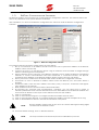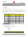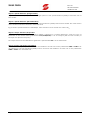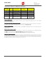
1
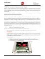
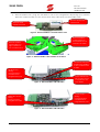
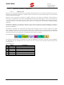
SINUS PENTA BACnet PROGRAMMING INSTRUCTIONS SINUS PENTA MULTIFUNCTION AC DRIVE USER MANUAL BACNet Programming Instructions- Upd. 27/10/2008 R. 01 VER. SW 1.66x English This manual is integrant and essential to the product. Carefully read the instructions contained herein as they provide important hints for use and maintenance safety. This device is to be used only for the purposes it has been designed to. Other uses should be considered improper and dangerous. The manufacturer is not responsible for possible damages caused by improper, erroneous and irrational uses. Elettronica Santerno is responsible for the device in its original setting. Any changes to the structure or operating cycle of the device must be performed or authorized by the Engineering Department of Elettronica Santerno. Elettronica Santerno assumes no responsibility for the consequences resulting by the use of nonoriginal spare-parts. Elettronica Santerno reserves the right to make any technical changes to this manual and to the device without prior notice. If printing errors or similar are detected, the corrections will be included in the new releases of the manual. Elettronica Santerno is responsible for the information contained in the original version of the Italian manual. The information contained herein is the property of Elettronica Santerno and cannot be reproduced. Elettronica Santerno enforces its rights on the drawings and catalogues according to the law. Elettronica Santerno S.p.A. Strada Statale Selice, 47 – 40026 Imola (BO) Italy Tel. +39 0542 489711 – Fax +39 0542 489722 www.elettronicasanterno.com [email protected] Page 1 of 9 SINUS PENTA BACnet PROGRAMMING INSTRUCTIONS 1. BAC NET F IELDBUS C OMMUNICATIONS B OARD BACnet is a data communication protocol specifically designed for building automation and control systems. Building automation systems (or building management systems) using BACnet incorporate a wide variety of applications and components into the one system. The applications cover heating, ventilation and air conditioning (HVAC), power monitoring, lighting control, access control and fire alarms for the entire building. Developed under the guidance of the American Society of Heating, Refrigerating and Air-Conditioning Engineers (ASHRAE), BACnet is an American national standard, a European standard, a national standard in more than 30 countries and an ISO global standard. The BACnet communications board allows interfacing a Sinus PENTA inverter with an external control unit through a communications interface using a BACnet protocol of either BACnet IP or BACnet MSTP. The user configuration software allows the setting of global Node ID and Network Number in addition to configuration of IP address and Subnet mask to suit BACnet IP using the Ethernet protocol and System Node, Baud rate, party, data bits and stop bits for BACnet MSTP using the RS485 protocol. For the purposes of this manual, A BACnet device can be considered to be a piece of hardware such as a Sinus Penta drive. Each BACnet device will have a number of associated BACnet Objects, corresponding to parameters, measurements, and the like. In this application, the Sinus Penta Drive has a minimum of 13 objects of the ‘Analogue Value’ type for communicating various parameters between the drive and the BACnet network. This minimum number of objects can be increased to include additional measurements as required by the user. 1.1. BAC N E T C OMMU N I C A TI ON C A RD S Two PCB’s are provided as part of the Sinus PENTA BACnet fieldbus option: 1. ES919 interface board – plugs into Slot B of the ES821 control card inside the Sinus Penta. <PIC OF ES919> Once board ES919 is fitted, connector DB9 port/RS-485 installed on the inverter will automatically disable. To use the DB9/RS485 port temporarily to program the drive (e.g using Remote Drive) simply toggle the DIP switches SW1 on the ES919 to enable/disable. The RJ45 keypad/modbus port is unaffected by the addition of the ES919. To install the ES919: Turn off the inverter and wait 5 minutes for the DC bus capacitors to discharge Remove the front cover allowing access to the expansion ports on the ES821 control card Fit ES919 ensuring that all contacts enter the relevant housing in the signal connector Configure DIP switches as described above Figure 1 - Location of the mounting position of ES919 Page 2 of 9 SINUS PENTA 2. BACnet PROGRAMMING INSTRUCTIONS BACnet Fieldbus PCB – plugs into the ES919 in one of two configurations depending upon whether BACnet IP or BACnet MSTP is to be used to allow easy cable entry into the fieldbus card. BACnet IP Ethernet socket port BACnet MSTP EIA485 standard Figure 2 - BACnet Fieldbus Communications Card BACnet fieldbus card located on left of ES919 for use with BACnet MSTP BACnet fieldbus card located on right of ES919 for use with BACnet IP Figure 3 – BACnet fieldbus card installed on the ES919 GP105 LED indicates that BACnet fieldbus is alive for BACnet IP & MSTP LB LED flickers during communication over BACnet IP using Etherent port Figure 4 - BACnet fieldbus LED indication LA LED flickers during communication over BACnet IP using Etherent port TX/RX LED’s flicker during communication using BACnet MSTP Figure 5 - BACnet fieldbus LED indication Page 3 of 9 Power LED should be lit when power is supplied to the Sinus PENTA SINUS PENTA 1.2. BACnet PROGRAMMING INSTRUCTIONS BAC N E T F I E LD B U S T E RMI N A LS 1.2.1. BAC N E T IP BACnet IP is a popular international LAN standard widely deployed in commercial applications using the Ethernet communication medium. In addition, BACnet IP devices can take advantage of the Internet and Internet based technologies. Ethernet is fast, running from 10 Mbit/s to 10Gbit/s, and runs on a variety of media-STP, coaxial cable, or fiber optics. Using BACnet IP will allow standard Ethernet based hardware right up to the end node device – such as a Santerno VSD. BACnet IP is the latest version of BACnet to be released and is quickly growing in popularity due to its fast data transfer speed and use of inexpensive and readily available Ethernet hardware. The Ethernet interface is a cable bus which runs over copper or fiber. The copper interfaces use either a coax line or differential twisted pairs, while the fiber runs use fiber-optic cables. The Ethernet network is defined by IEEE 802.3 The Ethernet standard uses Manchester Encoding and Decoding. Access control is gained via Carrier Sense, Multiple Access with Collision Detect (CSMA_CD). Preamble Field: A 56 bit pattern of alternating ones and zeros which are used to synchronize the receiver clock to the incoming data packet. SFD Field: Start Frame Delimiter Field, indicates the beginning of the frame; [10101011]. Typical Ethernet packet is shown below: The board is provided with a standard RJ-45 connector (IEEE 802) for Ethernet connection 10/100 (100BaseTX, 10Base-T). The pin arrangement is the same as the one used for each network board computers are equipped with. Pin arrangement: N. 1 2 3 4 5 6 7 8 Name TD+ TDRD+ Term Term RDTerm Term Page 4 of 9 Description Positive signal transmission line Negative signal transmission line Line receiving positive signals Terminated pair – not used Terminated pair – not used Line receiving negative signals Terminated pair – not used Terminated pair – not used SINUS PENTA 1.2.2. BACnet PROGRAMMING INSTRUCTIONS BAC N E T MSTP BACnet MSTP uses the EIA-485 signalling standard. This is a shielded twisted-pair (STP) LAN operating at speeds from 9.6 kbit/s to 76.8 kbit/s. This LAN type is low cost and particularly suitable for unitary controller communications. EIA-485 (formerly RS-485 or RS485) is an electrical specification of a two-wire,[1] half-duplex, multipoint serial communications channel. Since it uses a differential balanced line over twisted pair (like EIA-422), it can span relatively large distances (up to 1,200 m). This standard is now administered by the TIA and is titled TIA-485-A Electrical Characteristics of Generators and Receivers for Use in Balanced Digital Multipoint Systems (ANSI/TIA/EIA-485-A-98). EIA-485 signalling standard specifies the following: Type of cable Min. cross-section of conductors Max. length Characteristic impedance Standard colours Screened cable composed of balanced D1/D0 pair + common conductor (“Common”) AWG24 corresponding to 0.25 sq mm. For long cable length, larger crosssections up to 0.75 sq mm are recommended. 1000 metres based on the max. distance between two stations Better if exceeding 100 (120 is typically recommended) Yellow/brown for D1/D0 pair, grey for “Common” signal Pin configurations for the BACnet MSTP fieldbus card are as follows: PIN FUNCTION + (TX/RX A) Differential input/output A (bidirectional) according to standard EIA-485. Positive polarity with respect to + for one MARK. (TX/RX B) Differential input/output B (bidirectional) according to standard EIA-485. Negative polarity with respect to - for one MARK. G (GND) control board zero volt. Common according to EIA-485 association. Page 5 of 9 SINUS PENTA 1.3. BACnet PROGRAMMING INSTRUCTIONS BAC N E T C ON FI G U RA TI ON S OFTWA RE The BACnet fieldbus communication kit contains BACnet configuration software. This software allows the user to set parameters for a specific BACnet installation After installation, run ‘Sinus Penta BACnet configurator.exe’ which will load the BACnet configuration software. Figure 6 - BACnet Configuration Software To configure and download the settings follow the steps below: 1. Set up a connection on IP address 192.168.1.X from the host PC (Default IP address of the BACnet fieldbus card is 192.168.1.24) 2. Connect the host PC to the BACnet device using an ethernet crossover cable or straight through cable if connecting from a Hub/Switch. 3. Ping the BACnet device using the ‘Ping BACnet gateway’ button within the BACnet configurator software to ensure communication has been achieved. A command window will appear, containing the IP address of any BACnet fieldbus devices that the host PC can detect. 4. Select your choice of BACnet IP or BACnet MSTP within the BACnet configuration software 5. For BACnet IP, enter a desired IP address, Subnet mask and BACnet port, and select DHCP if required 6. For BACnet MSTP, enter the MAC address, baud rate, parity, # stop bits, # data bits and highest MAC address on the network 7. Enter the BACnet device instance and the Network Number 8. By selecting the ‘Optional extra measurements’ checkbox, you can select from a range of measure parameters which can be transmitted from the Sinus PENTA over the BACnet fieldbus. See next section for details on the layout of the data received over the fieldbus. 9. Click on ‘Create Files’ 10. Click on ‘Download config file’ to configure the BACnet fieldbus network card 11. Click on ‘Download IP data file’ to configure the BACnet fieldbus network card (BACnet IP only) 12. Click on ‘Restart BACnet Device’ after the download has completed. NOTE: BACnet fieldbus card is back on-line once the ‘GP105’ LED begins flashing again located next the Ethernet socket. 13. To restore default settings, click on ‘Restore Defaults’. NOTE: Page 6 of 9 The Output Window will detail all processes undertaken by the user SINUS PENTA BACnet PROGRAMMING INSTRUCTIONS 2. EXCHANGED PARAMETERS The tables below shows the Sinus Penta parameters exchanged via BACnet fieldbus. Each table contains: 1) the parameter code; 2) its description; 3) its range; 4) its unit of measure (also indicated on the display); N.B.: each parameter is exchanged as a 32 bit floating point number, using the IEEE 754 standard It is assumed that for BACnet operation where the speed reference and digitial control is via the BACnet fieldbus, C143 C146 is set as 5:Serial Link for correct operation. For PID control where the reference (setpoint) and feedback is sent over the BACnet fieldbus, it is assumed that C285 C290 is set to 5:Serial Link. F ROM BAC NET NETWORK TO S INUS P ENTA Analogue Value Object 1) Code 1 M035 2 M042 3 M043 4 M045 5 M047 PID Reference 6 M048 PID Feedback 2) Description Digital Inputs from FIELD BUS Speed reference from FIELD BUS (integer portion) Speed reference from FIELD BUS (decimal portion) Torque reference/ Torque limit 3) Range 4) Unit of Measure – - – 32000 + 32000 rpm – 0.99 + 0.99 rpm – 500 + 500 – 100 + 100 – 100 + 100 % % % Object 1: digital inputs from field bus The virtual digital inputs via the Fieldbus are the low byte of the element. To read the virtual digital inputs, convert the value read in object 6 as a decimal integer into a 16-bit binary number. The eight least significant bits (1-8) correspond with Digital Inputs 1 to 8. For example, if the number received in this object was ‘71’: 7110 = 00000000 010001110 The least significant bits are on the right hand side, 01000111 From this: Input 1 = ON Input 2 = ON Input 3 = ON Input 4 = OFF Input 5 = OFF Input 6 = OFF Input 7 = ON Input 8 = OFF Analogue Value Object 1 MDI1 MDI2 MDI3 MDI4 MDI5 MDI6 MDI7 MDI8 The logic status of these bits is included in the overall status of the inverter digital inputs (measure M031). Page 7 of 9 SINUS PENTA BACnet PROGRAMMING INSTRUCTIONS Object 2: Speed Reference (Integer Portion) Object 2 of the memory map details the integer portion of the speed reference (M042) in either IFD, VTC or FOC mode. Object 3: Speed Reference (Decimal Portion) Object 3 details the decimal portion of the speed reference (M043) ONLY IN FOC MODE. The value written at the SCADA end will be between -0.99 and +0.99 E.g to send a speed reference of XXX.50rpm, then element 2 must contain the value 0.5010 Object 4: Torque reference/torque limit The torque reference/torque limit position (M045) is defined as a ‘Torque Reference’ when the type of reference of the active motor (parameters C011/C054/C097) is set as 1:Torque (IFD and VTC modes) or 2:Torque with Speed Limit (FOC). The torque limit from the FIELD BUS is significant if parameter C147 is set as 5:Serial Link Objects 5 and 6: PID reference/feedback The PID reference (M047) can be sent from the fieldbus if at least one of the parameters C285 to C287 is set as 5:Serial Link. The PID feedback (M049) can be sent from the fieldbus if at least one of the parameters C288 to C290 is set as 5:Serial Link. Page 8 of 9 SINUS PENTA BACnet PROGRAMMING INSTRUCTIONS F ROM S INUS P ENTA Analogue value Object 1) Code 7 8 9 10 11 12 13 M037 M038 M039 14…n Mxxx TO BAC NET NETWORK 2) Description 3) Range 4) Unit of Measure Digital inputs Analog input REF Analog input AIN1 Analog input AIN2 Digital outputs Status Alarms – +/-10V or 0-20mA +/-10V or 0-20mA +/-10V or 0-20mA V or mA V or mA V or mA - As per table As per table Scaled to standard units where appropriate Measure Values as selected As per Mxxx Object 7: Digital Inputs As per Object 1, convert the number to binary, and the eight least significant bits of the number correspond to Digital inputs Objects 8,9,10: REF, AIN1, AIN2 Analogue Signal The REF (M037), AIN1 (M038), AIN2 (M039) analogue signals from the Sinus Penta will present as numbers in the range +/-10V or 0-20mA depending upon the selection of P050, P055, P060. Object 11: Digital Outputs As per Object 1, convert the number to binary, and the four least significant bits of the number correspond to Digital inputs Objects 12 and 13: Status + Alarms The Objects for Status and alarms will present a number that corresponds to the appropriate table: The Status codes can be found in Table 103: Status List of the Programming Manual The Alarm codes can be found in Table 101: Alarm Codes List of the Programming Manual Object 14…x: Mxxx parameters Using the BACnet configuration software, a selection of Mxxx parameters can be selected to be viewed over the fieldbus. the order of assignment of Measurements from the drive to BACnet objects is based on the order in which they appear in the list of available measures- the top-most selected extra measure will be assigned to object 14, the next one down to 15, and so on. Page 9 of 9