1
ETL BLAST CHILLER SERIES
USER MANUAL
1.GENERAL DOCUMENTATION
The present manual is exclusively valid and applicable to the following products series:
Etl Series
MODEL NUMBER
GBF15-11S
GBC30SG
GBF30-17SG
GBF44-26SG
GBF30-17SP
GBF44-26SP
GBC39S
GBF39-24S
GBF52-37S
GBF61-44S
GBF77-55S
GBF176-143S
GBF242-209S
GBC88S
GBF88-66S
GBF143-110S
GBC112S
GBF112-77S
GBF171-132S
GBF440-385R
GBF837-727R
CHILLING
OUTPUT
15
30
30
44
30
44
39
39
52
61
77
176
242
88
88
143
112
112
171
440
837
FREEZING OUTPUT
11
NO FREEZING
17
26
17
26
NO FREEZING
24
37
44
55
143
209
NO FREEZING
66
110
NO FREEZING
77
132
385
727
UNIT TYPE
S
SG
SG
SG
SP
SP
S
S
S
S
S
S
S
S
S
S
S
S
S
R
R
1.1General information
• This manual is an integral part of the
product, providing all the information
required to ensure correct installation,
operation and maintenance of the machine.
• Read the manual carefully, making
reference to it for machine operation. Keep
the manual in a safe place where it can
be accessed by all authorised operators
(installers, operators and service
personnel). The european series machines
are been constructed in compliance with
the directives 73/23/CEE (low-voltage),
89/336/CEE (electromagnetic compatibility)
and 98/37/CE (machines; for certain
models only), while, the United states
series machines are been constructed in
compliance with the standard for Safety
Commercial Refrigerators and Freezers,
ANSI/UL 471, Issued: 2006/01/27 Ed:9
Rev:2008/10/24; Refrigeration Equipment
General Instruction No 1-2 (R2004);
CAN/CSA-C22.2 No.120, Issue:1991/01/01
Ed:3; Commercial Refrigerators and
Freezers, NSF/ANSI 7, Issue: 2007/06/01.
• The machine has been designed for
professional applications only and should
only be operated by qualified personnel.
• The machine must only be used for the
purposes for which it was designed, i.e.
for chilling and freezing food products.
The machine must not be used for products
requiring constant temperature control
and recording, such as:
- heat-sensitive chemicals,
- medicines or
- blood products.
• The manufacturer declines all
responsibility for any damage caused by
incorrect or unreasonable machine use,
such as:
• improper use by untrained persons;
• technical modifications or operations
not suited to specific models;
• use of non-original or non-specific spare
parts;
• failure to follow the instructions given in
this manual.
1.2 Installation
The machine must be installed by a
specialised technician authorised by and in
compliance with the instructions given in
this manual. In the event that the machine
is fitted with a remote condenser unit, the
installation technician is responsible for
checking all connections in compliance with
the instructions given by for plant and
machine installation.
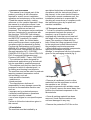
1.3 Transport and handling
• To load or unload the machine and/or
components from/onto the means of
transport, use a lift truck or fork lift
equipped with forks that are at least half
the length of the machine housing; use a
crane if the machine is fitted with eye
bolts. Select the lifting equipment suited
to the weight and overall dimensions of
the packaged machine/components.
• When handling the machine/ components,
apply all precautions to prevent
damage, in compliance with the information
given on the packaging material (fig.1).
1.4 Unpacking
• Remove all cardboard, wood or other
materials from the wood base on which
the machine is set. Lift the
machine/components with suitable means
(e.g. lift truck), remove the wood base, then
position the machine/components in the
allocated site.
• Once all packing material has been
removed, check that the machine has
not been damaged in any way.
• Remove the protective PVC film on the
stainless steel panels from all internal and
external surfaces (fig. 2).
• Always wear protective gloves when
handling
packing material and the wood base.
• NB Dispose of packing materials in
compliance
with disposal regulations applied
in the country where the machine is to be
installed. Never dispose of materials in
the environment.
1.5 General safety regulations
Failure to observe the recommendations
made by the present manual will be at the
entire responsibility of the machine user.
The main safety regulations are as follows:
- do not touch the machine with moist
or wet hands or feet;
- never operate the machine while
barefoot;
- do not insert screwdrivers, cooking
utensils or any other object between
the guards and moving parts;
- before performing cleaning or routine
maintenance operations, disconnect
the machine from the power supply at
the master switch and the main knife
switch (if present);
- never pull on the power cable to
disconnect the machine from the power
supply.
2.INSTALLATION
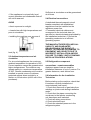
2.1 Data plate information
• Check that the data specified on the
plate correspond to the characteristics
of the power supply (V, kW, Hz, no. phases
and power available).
• The dataplate with appliance (fig.3)
specifications is located at the rear exterior
of the machine and/or on the electrical
boards The set-up of individual units and
the installation of condensers are subject to
the fire-safety regulations of the country in
which the machine is installed; seek all
necessary advice from the local firefighting
authorities. Bear in mind that the
intervention of safety valves or plug fuses in
the refrigerating circuit will lead to the
immediate discharge of refrigerant into the
environment.
2.2 Positioning
• The machine must be installed and
commissioned in complete compliance with
safety regulations, procedures and standing
laws.
• The installation technician bears the
responsibility of ensuring compliance with
fire safety requirements; seek all necessary
advice from the local firefighting authorities.
• Position the machine in the allocated site.
• Adjust the machine feet until the appliance
is perfectly level. In the case of particularly
heavy equipment, use appropriate lifting
means
• If the appliance is not perfectly level,
correct operation and condensate flow-off
will not be assured.
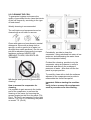
AVOID
• direct exposure to sunlight;
• closed sites with high temperatures and
poor air circulation;
• installing the machine near sources of
heat (fig. 4).
2.3 Ambient temperature and air
circulation
For air-cooled appliances, the maximum
ambient temperature for operation is 32°C.
Correct operation cannot be guaranteed at
higher temperatures. The machine may
operate safely to a maximum temperature
of 38°C. Remote condensing units must be
installed in special rooms or outdoors,
protected against direct sunlight by a
shelter or roof structure (at the cost of the
purchaser)..
Sufficient air circulation must be guaranteed
at all times
2.4 Electrical connections
A dedicated thermal-magnetic circuit
breaker compliant with established
regulations must be installed on the
appliance power line.
• Connected electrical cables must
correspond to the technical data (as
specified on electrical drawings provided by
the installation technician). Connect the
grounding conductor to an efficient
grounding system.
THE MANUFACTURER DECLINES ALL
LIABILITY AND GUARANTEE
OBLIGATIONS IN THE EVENT OF
INJURY TO PERSONS OR DAMAGE TO
EQUIPMENT AND OBJECTS DUE TO
INCORRECT INSTALLATION AND/OR
FAILURE TO COMPLY WITH STANDING
INSTALLATION REGULATIONS.
2.5 Refrigeration component
connections - remote assemblies
Appliance power lines are sized for
installation distances of up to 5 metres. For
greater distances, seek advice from .
2.6 Information for the installation
Technician
Before starting up the machine, check that
it has been correctly installed and
commissioned (test report).
1. Check that there are no gas leaks from
weldings or joints made during installation
works.
2. Check that the pipes connecting the
condenser to the remote condensing
unit have been well insulated.
3. Check all wiring connections.
4. Check electrical input.
5. Check the standard pressure in the
refrigerant system.
.
6. check the expansion valve during
operation.
7. Perform at least one blast freezing cycle
(to the SET temperature) and one manual
defrosting cycle
In the event that the appliance or the
remote condensing unit have not been
transported in a vertical position (e.g. on
the back) or have been overturned during
installation works, allow at least 4 hours
before starting up the equipment.
• Inform the customer of the exact purpose
of the appliance, with specific reference
to the use and requirements of the
customer.
.
2.8 Appliance disposal
Demolish and dispose of the machine in
compliance with the regulations applied in
the country of installation, particularly in
regards to refrigerant gas and compressor
lubricant oil.
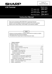
WEEE Notice
The Directive on Waste Electrical and
Electronic Equipment (WEEE), which
entered into force as European law on 13th
February 2003, resulted in a major change
in the treatment of electrical equipment at
end-of-life. The purpose of this Directive is,
as a first priority, the prevention of WEEE,
and in addition, to promote the reuse,
recycling and other forms of recovery of
such wastes so as to reduce disposal.
The appliance must be installed and put
into service by a technician authorised.
2.7 Safety and control systems
• Door micro switch: shuts down fan
operation in the cell when the door is
opened.
• General fuses: protect the power circuit
against short circuiting and overloads.
• Compressor heat relay: intervenes in the
event of overloads or operating faults.
• Safety pressure switch: intervenes in the
event of excessive pressure in the
refrigerant circuit.
• Plug fuses: intervene in the event of
overpressure or operating fault in the safety
pressure switch (see above).
• Chamber temperature control: operated
by the electronic board by means of a
probe inside the cell.
• Temperature control end defrost cycle:
controlled by the electronic board by
means of the probe in the evaporator
The WEEE logo on the product or on its box
indicates that this product must not be
disposed of or dumped with your other
household waste. You are liable to dispose
of ali your electronic or electrical waste
equipment by relocating over to the
specified collection point for recycling of
such hazardous waste. Isolated collection
and proper recovery of your electronic and
electrical waste equipment at the time of
disposal will allow us to help conserving
natural resources. Moreover, proper
recycling of the electronic and electrical
waste equipment will ensure safety of
human health and environment. For more
information about electronic and electrical
waste equipment disposal, recovery, and
collection points, please contact your local
city centre, WEEE professional disposal
service, shop from where you purchased
the equipment, or manufacturer of the
equipment.
3. ADVICE TO ENSURE EFFICIENT APPLIANCE
OPERATION
3.1 Shut-down procedures
In the event of emergency, shut down the
appliance by switching off power at the
main panel, by means of the knife switch or
by removing the plug from the power
socket.
3.2 Operating tips
c) Position trays inside the tray
compartment
as far as they will go, as close as
possible to the evaporator.
Before starting up the appliance, clean the
inside of the cell thoroughly.
3.3 Pre-cooling
Before using the appliance for the first
time, or after a prolonged period of disuse,
pre-cool the cell by running an empty
cycle until the set operating temperature
has been reached. To ensure optimal
performance without any alteration to food
quality: arrange food products in such a
way as to favour the circulation of cold air
throughout the cell; open the door as little
as possible.
d) Position the core probe at the centre of
the largest product or food item; make
sure that the tip of the probe does not
protrude or touch the tray.
The probe must be cleaned and sanitised
before each new cycle (operation)
to prevent inadvertent contamination.
3.4 Loading the appliance
a) Ensure that foods to be chilled and/or
frozen are separate and do not have a
thickness greater than 50-80 mm. Do not
load the appliance beyond the quantity by
the manufacturer.
b) Ensure that there is sufficient clearance
between trays to enable free air circulation.
If the appliance is not completely full,
distribute the trays and foods evenly
throughout the available space.
e) Avoid covering the trays and/or
containers
with insulating covers or film. The
more the product is insulated, the more
time is required for chilling or freezing.
Trays must be packaged when the product
has been chilled, before being
placed in storage.
4.PROGRAMMING AND OPERATING INSTRUCTIONS
Please read these instructions carefully prior to installation and use, and follow all the
precautions for installation and electrical connections; keep these instructions with the
device for future consultation.
The device must be disposed of in accordance with local regulations pertaining to the
collection of electrical and electronic appliances.
4.1 Introductory information
The device has the following operational states:
•"on" (the device is switched on and an operating cycle is running)
•"stand-by" (the device is switched on and no operating cycle is running, but it is
possible to select one)
•"off" (the device is switched on and no operating cycle is running, and it is not
possible to select any).
If power is interrupted while in the "on" mode, when power is restored the device will be in
the same state and the operational cycle will be restarted from the point reached when the
power interr. occurred .
If power is interrupted while in "stand-by" or "off" mode, when power is restored the device
will be in the same state.
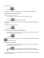
4.2 Switching the device on/off ("off"/"stand-by")
•ensure no procedures are running
•press
The regulators
B1 for 5 s
are switched off while in "off" mod.
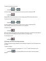
4.3 Starting/stopping an operational cycle ("on"/ "stand-by")
•ensure no procedures are running
•press
The regulators
B1
are switched off while in "stand-by" mode.
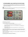
4.4 The display
In the "on" state, during normal operation, display DY1 shows:
•the temperature measured by the needle probe if a set-temperature chilling or
freezing operation is ongoing
•the temperature of the cabinet if a set-temperature chilling, or timed freezing or a
storage operation is ongoing.
Display DY2 shows:
•the amount of time for a blast chill or freezing operation, if these are ongoing
While in "stand-by" mode, display DY1 shows the cabinet temperature and display DY2
shows "- - -".
While in "off" mode, display DY1 shows "OFF" and display DY2 is off.
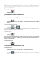
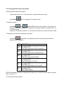
4.5 Displaying the temperatures detected by the probes
•ensure the device is in "off" mode and no procedures are running
•press
for 5 s: display DY1 will show the message
B2 + B4
"Pr1" and display DY2 will show the cabinet temperature
•press B4
below.
or B6
to select one of the labels shown in the table
To exit the procedure:
•press B1
If there is no condenser probe (parameter P3 = 0), label "Pr4" will not be displayed.
4.6 Starting/stopping manual defrosting
To start defrosting in manual mode:
•ensure the device is in "off" mode and no procedures are running
•press B11
display DY1 will show “dEF”.
If the evaporator temperature is above the value set by parameter P23, defrosting will not
be activated.
To stop defrosting in manual mode:
•press B11
4.7 Switching on the UV light (cabinet sterilisation)
•ensure that the device is in "stand-by" mode, that no procedures are running and
that the micro port input is not active
•press B10
The UV light is turned on for the period of time established by parameter P46 or until B10
is pressed once more.
4.8 Heating the needle probe
•ensure that the device is in "stand-by" mode, that no procedures are running and
that the micro port input is not active
•press B2
for 5 s: the needle probe will be heated until it reaches the
temperature set by parameter P47 or at most for the period of time set by parameter
P48.
If the temperature detected by the needle probe is above the value set by parameter P47,
heating will not be started.
The micro-port input will not be reported during needle probe heating.
4.9 Buzzer mute
•ensure no procedures are running
•press B4
After the period of time established by parameter P56 has elapsed, the buzzer is
automatically muted.
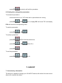
5. OPERATIONAL CYCLES
5.1 Introductory information
The device has the following operational cycles:
•hard set-temperature chilling and storage
•normal set-temperature chilling and storage
•set-temperature freezing and storage
•hard timed chilling and storage
•timed normal chilling and storage
•timed freezing and storage.
Set-temperature cycles are preceded by a test to check correct needle probe insertion
(see parameters P14 and P15); if the result of the test is negative, cycles will be started in
timed mode.
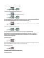
5.2 Hard set-temperature chilling and storage cycle
To select the cycle:
•ensure the device is in "off" mode and no procedures are running
•press B7
switch on.
: display DY1 will show the operational set point and LED B7 will
To alter the first step operational setpoint:
or B6
•press B4
To alter the second step operational setpoint:
•press B7
for 5 s: LED B7 will flash
•press B4
or B6
These settings remain active until another cycle is selected. Also, it is possible to set the
first step operational setpoint by means of parameter P6 and the second step operational
setpoint by means of parameter P4; the hard chill process progresses from the first step to
the second when the temperature detected by the needle probe reaches the value set by
parameter P12.
To start the cycle:
•press B1
When the temperature detected by the needle probe reaches the value set by parameter
P10, the buzzer is activated for the length of time set by parameter P55 and the device
switches to storage mode.
To interrupt the cycle:
•press B1
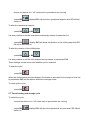
5.3 Normal set-temperature chilling and storage cycle
To select the cycle:
•ensure the device is in "off" mode and no procedures are running
•press B8
switch on.
: display DY1 will show the operational setpoint and LED B8 will
To alter the operational setpoint:
•press B4
or B6
These settings remain active until another cycle is selected. It is also possible to set the
operational setpoint by means of parameter P4.
To start the cycle:
•press B1
When the temperature detected by the needle probe reaches the value set by parameter
P10, the buzzer is activated for the length of time set by parameter P55 and the device
switches to storage mode.
To interrupt the cycle:
•press B1
5.4 Set-temperature freezing and storage cycle
To select the cycle:
•ensure the device is in "off" mode and no procedures are running
•press B9
switch on.
: display DY1 will show the operational setpoint and LED B9 will
To alter the operational set point:
•press B4
or B6
These settings remain active until another cycle is selected. It is also possible to set the
operational set point by means of parameter P5.
To start the cycle:
•press B1
When the temperature detected by the needle probe reaches the value set by parameter
P11, the buzzer is activated for the length of time set by parameter P55 and the device
switches to storage mode.
To interrupt the cycle:
•press B1
5.5 Hard timed blast chilling and storage cycle
To select the cycle:
•ensure the device is in "off" mode and no procedures are running
•press B7
switch on.
: display DY1 will show the operational set point and LED L7 will
To alter the first step operational set point:
•press B4
or B6
To alter the second step operational set point:
•press B7
per 5 s: LED L7 will flash
•press B4
or B6
It is also possible to set the first step operational set point by means of parameter P6 and
the second step operational set point by means of parameter P4.
•press B3
: display DY2 will show the duration of the chilling step and LED
L3 will be switched on.
To alter the duration of the chilling step:
•press B4
or B6
It is also possible to set the chill duration time by means of parameter P16.
These settings remain active until another cycle is selected. The hard chill process
switches from the first step to the second step once the period of time established by
parameter P18 has elapsed.
To start the cycle:
•press B1
When the chill duration time has elapsed, the buzzer is activated for the length of time set
by parameter P55 and the device switches to storage mode.
To interrupt the cycle:
•press B1
5.6 Normal timed chilling and storage cycle
To select the cycle:
ensure the device is in "off" mode and no procedures are running
•press B8
switch on.
: display DY1 will show the operational setpoint and LED L8 will
To alter the operational setpoint:
•press B4
or B6
It is also possible to set the operational setpoint by means of parameter P4.
•press B3
: display DY2 will show the duration of the chilling step and LED
L3 will be switched on.
To alter the duration of the chilling step:
•press B4
or B6
It is also possible to set the chill duration time by means of parameter P16.
These settings remain active until another cycle is selected.
To start the cycle:
•press B1
When the chill duration time has elapsed, the buzzer is activated for the length of time set
by parameter P55 and the device switches to storage mode.
To interrupt the cycle:
•press B1
5.7 Timed freezing and storage cycle
To select the cycle:
•ensure the device is in "off" mode and no procedures are running
•press B9
switch on.
: display DY1 will show the operational set point and LED L9 will
To alter the operational set point:
•press B4
or B6
It is also possible to set the operational set point by means of parameter P5.
•press B3
:
display DY2 will show the duration of the freezing step LED L3 will be switched on.
To alter the duration of the freezing step:
•press B4
or B6
It is also possible to set the freeze duration time by means of parameter P17.
These settings remain active until another cycle is selected.
To start the cycle:
•press B1
When the freezing step duration time has elapsed, the buzzer is activated for the length of
time set by parameter P55 and the device switches to storage mode.
To interrupt the cycle:
•press B1
5.8 Storage, selection and starting a program
The device allows storage of operation cycle settings in programs; up to 99 programs can
be stored.
To store a program:
•proceed as described in paragraphs 3.5, 3.6 or 3.7 without starting the cycle
•press B12
program
for 5 s: display DY1 will show the label of the first unused
•press B4
or B6
to select another label
•press B12
for 5 s: the device will store the program and exit from the
procedure (any programs with the same label will be overwritten).
To select and start a stored program:
•ensure the device is in "stand-by" mode and no procedures are running
•pressB12
•press B4
: display DY1 will show the label of the first program
or B6
to select a program
•press B1
To display the label of the current program:
•press B12
5.9 Additional functions accessible during operational cycles
To display the cabinet temperature during a set-temperature chilling step or during a settemperature freezing step:
•press the key relating to the current cycle: display DY1 displays the cabinet
temperature for 5 s.
To display the temperature detected by the needle probe during a timed chilling step,
timed freezing step or during storage:
•press B2
probe for 5s.
: display DY1 shows the temperature measured by the needle
To display the time elapsed since starting a chilling or freezing step:
•press B4
: display DY2 shows the elapsed time for 5 s.
If the key is pressed during the storage phase, display DY2 will show the effective duration
of the chilling or freezing process
6. SETTINGS
6.1 Setting the date and time
To access the procedure:
•ensure the device is in "off" mode and no procedures are running
To alter the date and time:
•press B3
for 5 s: display DY1 will show "YY" and display DY2 will show the
last two digits corresponding to the year
•press B4
or B6
to change the year
•press B3
: display DY1 will show "NN" and display DY2 will show the digits
corresponding to the month (the month is displayed in 12 month format)
•press B4
or B6
to change the month
•press B3
: display DY1 will show "dd" and display DY2 will show the digits
corresponding to the day (days are displayed in 31 day format)
•press B4
or B6
to change the day
•press B3
: display DY1 will show "hh" and display DY2 will show the digits
corresponding to the hour (hours are displayed in 24 hour format)
•press B4
or B6
to change the hour
•press B3
: display DY1 will show "nn" and display DY2 will show the digits
corresponding to the minutes
•press B4
or B6
to change the minutes
•press B3
: the device will exit the procedure.
6.2 Setting the configuration parameters
To access the procedure:
•ensure the device is in "off" mode and no procedures are running
•press B4
+ B6
for 5 s: display DY1 will show "PA" and display
DY2 will show the corresponding value.
To select a parameter:
•press B4
or B6
To modify a parameter:
•press B3
•press B4
: LED L3 will be switched on
or B6
within 60 s
•press B3
To exit the procedure:
•press B4
+ B6
for 5s.
7. HACCP
7.1 Introductory information
The device is capable of storing up to 10 HACCP alarms, after which the most recent
alarm will overwrite the oldest.
The device can furnish the following information:
•the critical value
•the date and time at which the alarm occurred
•the alarm duration (from 1 minute to 999 minutes, " - - -" if the alarm is ongoing).
CODE ALARM TYPE (AND CRITICAL VALUE)
cabinet probe error (the temperature of the cabinet when
Er0
the alarm condition occurred)
evaporator probe alarm (the maximum cabinet temperature
Er1
during the alarm condition)
needle probe alarm (the maximum cabinet temperature
Er3
during the alarm condition)
minimum) cabinet temperature alarm (the minimum cabinet
AL
temperature during the alarm condition)
maximum) cabinet temperature alarm (the maximum
AH
cabinet temperature during the alarm condition)
condenser temperature alarm (the maximum cabinet
Ht
temperature during the alarm condition)
micro port input alarm (the maximum cabinet temperature
d-r
during the alarm condition)
high pressure input alarm (the maximum cabinet
HP
temperature during the alarm condition)
low pressure input alarm (the maximum cabinet
LP
temperature during the alarm condition)
compressor thermal protection input alarm (the maximum
HA
cabinet temperature during the alarm condition)
7.2 Viewing HACCP alarm information
Viewing HACCP alarm information:
•ensure the device is in "off" mode and no procedures are running
•press B12
for 5 s: display DY1 will show "Prt".
To select an alarm:
•press B4
or B6
display DY1 will show the number of the alarm (for
example "n03") and display DY2 will show the relevant code (for example "AH", or
one of the codes
reported in the table in section 5.1; the lower the number, the older the alarm itself).
To display the information relating to the alarm:
•press B3
repeatedly: the display will show the following information in
sequence (for example):
INFO MEANING
St
on display DY1
y07
on display DY2
The alarm occurred in 2007 (continued ...)
M03 on display DY1
d26
on display DY2
The alarm occurred on 26 March 2007
on display DY1
h16
d30
on display DY2
The alarm occurred at 4:30pm
t
on display DY1
8
on display DY2
The critical value is 8 °C/8 °F
on display DY1
dur
75
on display DY2
The alarm has lasted for 75 minutes
DY1 on display DY1
AH
on display DY2
The selected alarm
LED L13 provides information relating to the status of the HACCP alarm memory; please
refer to section 7.1.
To exit the information series:
•press B4
or B6
display DY1 will show the number of another alarm
and display DY2 will show the corresponding code.
To exit the procedure:
•press B12
for 5 s.
7.3 Deleting the HACCP alarm list
•set parameter P73 to 1.
8. DATA PRINTING
8.1 Introductory information
The device has a serial port for communicating with the PM 100AX9S001 print module.
8.2 Connecting the PM 100A X9S001 print module
Connecting the PM 100A X9S001 print module:
•ensure that parameter P71 is set to 1
•ensure that the print module baud rate is set to 9,600 baud
•ensure that the module parity is set to odd.
8.3 Printing operational cycle information
Printing operational cycle information:
•operational cycle start date
•operational cycle or program type (or one of the codes listed in the table below)
CODE
T>>>*
T*
T***
t>>>*
t*
t***
P01...99
MEANING
hard set-temperature chilling and storage
normal set-temperature chilling and storage
set-temperature freezing and storage
hard timed chilling and storage
timed normal chilling and storage
timed freezing and storage
program 01 ... 99
•printing time
•cabinet temperature (Pr1)
•temperature measured by the needle probe (Pr2, only if the operational cycle is a
set-temperature cycle)
•time of switchover to storage mode
•time of any operational cycle interruption.
Printing of the temperature occurs at operational cycle start, and at intervals (see
parameter P72).
8.4 Printing HACCP alarm information
The module prints the information reported in the table in section 5.2.
To print the information relating to the alarms:
•ensure the device is in "off" mode and no procedures are running
•press B12
for 5 s: display DY1 will show "Prt"
•press B12
To exit the procedure:
•press B12
for 5 s.
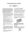
9. MAINTENANCE AND CLEANING
The information and instructions given in
this section address all persons operating
the appliance: the user, the maintenance
technician and non-specialised personnel.
Ensure that the electrical power to the
system has been disconnected before
carrying out any cleaning or
maintenance work on the appliance.
9.2 CLEANING THE CONDENSER
9.1 GENERAL SAFETY REGULATIONS
Recall the following regulations to ensure
that all cleaning and routine maintenance
operations are conducted safely.
- do not touch the machine with moist or
wet hands or feet;
- never operate the machine while
barefoot;
- do not insert screwdrivers, cooking
utensils or any other object between the
guards and moving parts.
- before performing cleaning or routine
maintenance operations, disconnect the
machine from the power supply at the
master switch and by pulling out the
plug;
- never pull on the power cable to
.disconnect the machine from the power
.supply.
Use a vacuum cleaner to prevent the dust
removed from being dispersed in the
surrounding area. To remove greasy
deposits, use a brush dipped in alcohol.
Removal of guards and safety devices
for the purposes of routine maintenance
is strictly prohibited. The manufacturer
declines all responsibility for accidents
causedby failure to observe the above
regulation.
Before starting up the appliance, clean
the inside of the cell thoroughly, as
described in par. 8.3.
To ensure correct and efficient air
condenser operation, it must be kept clean
to allow free circulation of air. This operation
should be performed at least once a month.
Use a non-metal brush to remove all dust
and debris from the condenser blades.
NEVER USE POINTED OR ABRASIVE
INSTRUMENTS TO SCRAPE APPLIANCE
SURFACES.
PERFORM THIS OPERATION ONLY
AFTER THE APPLIANCE HAS BEEN
SHUT DOWN
IMPORTANT
The condenser has sharp edges. Always
wear protective gloves, goggles and masks
when carrying out the above operations
9.3 CLEANING THE CELL
To guarantee hygiene and ensure the
quality of processed foods, clean the interior
of the cell frequently, according to the type
of food stored.
Weekly cleaning is recommended.
The cell interior and components can be
cleaned with a soft cloth or sponge.
Clean with water and non-abrasive neutral
detergents. Rinse with a damp cloth or
sponge, or with a gentle jet of water (no
stronger than mains pressure). Do not use
pointed or abrasive instruments to scrape
appliance surfaces. NEVER USE
ABRASIVE FLUIDS, SOLVENTS OR
THINNERS
Periodically, provide to clean the
evaporator, using nebulized hot water at low
pressure, and addressing the water throw
on the evaporator battery
Finished the cleaning, provide to dry the
evaporator using air pressure in order to
desiccate and remove the residues of
presence of water . After that refit the fan
panel in proper position.
NB Always wear protective gloves while
cleaning.
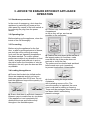
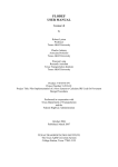
How to access the evaporator for
cleaning.
It is possible to gain access to the inside
part of the evaporator, to perform the
cleaning of the same, by removing the
screws located on the front fan panel (T14Pict.1, T5-Pict.3) and opening it to the right
side for T14 (Pict.2), or removing the panel
on model T 5. (Pict.4)
To carefully clean with a cloth the surfaces
adjacent to the evaporator and provide to
reassemble the frontal fans panel.
Important: Before starting the machine
pls
verify to have removed the equipments
used in precedence for the cleaning.
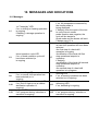
10. MESSAGES AND INDICATIONS
10.1 Messages
L1
“on”/”stand-by” LED
if on, a chilling or freezing operation
is ongoing
if flashing, a storage operation is
ongoing
L2
L3
timed operation cycle LED
if on, a timed operation cycle will
have been selected (or
is ongoing
L7
L8
L10
L12
normal chilling LED
if on, a normal chill operation has
been selected (or is
ongoing
UV light (cabinet sterilisation) LED
if on, the UV light is on (a cabinet
sterilisation operation is
ongoing)
program LED
if on, program storing, selection or
execution is ongoing
needle probe LED
if on, the temperature measured by
the needle probe is
being displayed
if flashing, then the result of the test
to verify correct needle
probe insertion was negative; the
cycle will be started in
timed mode and the buzzer will emit
5 beeps every 10 s
hard chill LED if on:
•a hard chill operation will have been
selected
•the first step of a hard chill
operation is ongoing
•modification of the hard chill first
step operational setpoint is
underway
if flashing:
•modification of the hard chill second
step operational setpoint is
underway
•the second step of a hard chill
operation is in progress
L9
freezing LED
if on, a freezing operation has been
selected (or is ongoing)
L11
defrosting LED
if on, defrosting is ongoing
L13
HACCP LED
if on, program storing, selection or
execution is ongoing
10.2 Indications
dEF if on, defrosting is ongoing
if flashing, drip-draining is ongoing
11. ALARMS
11.1 Alarms
Minimum cabinet temperature alarm
Remedies:
•check the cabinet temperature
AL
•see parameters P64 and P66
Consequences:
•the alarm output will be activated
Ht
Condenser temperature alarm
Remedies:
•check the condenser temperature
•see parameter P62
Consequences:
•the operational cycle will be
interrupted
•it will not be possible to start any
operational cycles
•the condenser fan will be switched
on
•the alarm output will be activated
High pressure input alarm
Remedies:
•check the causes of the input
activation
•see parameter P40
Consequences:
HP
•the operational cycle will be
interrupted
•the loads will be switched off
•it will not be possible to start any
operational cycles
•the alarm output will be activated
AH
dr
LP
Maximum cabinet temperature alarm
Remedies:
•check the cabinet temperature
•see parameters P65 and P67
Consequences:
•the alarm output will be activated
Micro-port input alarm
Remedies:
•check the causes of the input activation
•see parameter P38
Consequences if the alarm occurs while
in "on" mode:
•the compressor will be shut down
•if parameter P37 is set to 1, the
evaporator fan will be
switched off
•if parameter P59 is set to 0, the cabinet
light will be
switched on
•the condenser fan will be switched off
•if the UV light is on (i.e. if cabinet
sterilisation is ongoing),
the UV light will be switched off
Low pressure input alarm
Remedies:
•check the causes of the input activation
•see parameter P42
Consequences:
•the operational cycle will be interrupted
•the loads will be switched off
•it will not be possible to start any
operational
Compressor thermal protection input
alarm
Remedies:
•check the causes of the input
activation
•see parameter P44
HA Consequences:
•the operational cycle will be
interrupted
•the loads will be switched off
•it will not be possible to start any
operational cycles
•the alarm output will be activated
Power failure during an operational
cycle
Remedies:
•check the causes of the input
activation
rES Consequences:
•the operational cycle will be restored
from the point
where the power failure occurred
When the cause that triggered the alarm has been resolved, the device restores normal
operation.
12 INTERNAL DIAGNOSTICS
12.1 Internal diagnostics
Cabinet probe error
Remedies:
•see parameter P60
•check probe integrity
•check probe-device connection
•check the cabinet temperature
Er0 Consequences:
•the operational cycle will be
interrupted
•the loads will be switched off
•it will not be possible to start any
operational cycles
•the alarm output will be activated
Needle probe error
Remedies:
•the same as for the previous case,
but in relation to the
needle probe
Consequences:
•if a set-temperature chilling or
Er3
freezing operation is
ongoing, the operational cycle will be
interrupted
•it will not be possible to start any settemperature
operational cycles
•the alarm output will be activated
User interface-module communication
error
Remedies:
•check the user interface-module
connection
Err Consequences:
•if an operational cycle is ongoing, the
device will continue
to function normally
•it will not be possible to start any
operational cycles
Evaporator probe error
Remedies:
•the same as for the previous case,
but in relation to the
evaporator probe
Consequences:
Er1
•defrosting will last for the length of
time set by parameter
P24
•the evaporator fan will be switched
off during storage
•the alarm output will be activated
When the cause that triggered the alarm has been resolved, the device restores normal
operation.