1
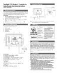
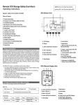
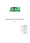
AT-ZG01U-SET Manual ATAL B.V. Ampèrestraat 35-37 NL-1446 TR PURMEREND Postbus 783 NL-1440 AT PURMEREND T (+31) 0299 630 610 F (+31) 0299 630 611 E [email protected] I www.atal.nl Content General introduction ........................................................................................................................................ 3 Features & Display Features and Modes .......................................................................................................... 3 Main unit view .................................................................................................................................................. 4 LCD Display Symbol .......................................................................................................................................... 5 SEU (Sensor Unit) Function Instruction ............................................................................................................ 6 RDU (Remote Display Unit) Function Instruction ............................................................................................. 7 Safety Notes ..................................................................................................................................................... 7 Caring For Product ............................................................................................................................................ 7 Installation Instructions .................................................................................................................................... 8 Customizing settings ......................................................................................................................................... 9 Specifications .................................................................................................................................................. 11 Fault codes & Troubleshooting Guide ............................................................................................................ 12 2 General introduction Indoor Air Quality (IAQ) is measure for the quality of air in interiors, the comfortable indoor environmental quality can make people feel fresh, work efficiency and good for the health. The CO2 concentration is the important factor of good indoor air quality. People breath in oxygen and breath out CO2, nowadays people often close the windows to avoid noise and enjoy the comfort living and working environment provided by air-conditioning systems, which results in the fact that the indoor concentration of CO2 is far higher than outdoor average. With the high CO2 concentration and non- proper ventilation, people will feel headaches, dull, drowsiness, loss of concentration and correspond to the high levels of dust, chemicals and bacteria in the air. Features & Display Features and Modes Dual Beam NDIR (Non-Dispersive Infrared) technology is used to measure CO2 concentration up to 50,000 ppm (parts per million) and electrochemical technology to measure O2 concentration up to 30%. With the SEU( Sensor Unit ) and RDU( Remote Display Unit ), it can connect up to 3 RDU for safety notices. Large digital LCD display clearly indicates the ambient CO2 / O2 Concentration and Temperature. Relay output can automatically control a fan to ventilate confined spaces. Audible and visual alarm indications. IP54 Water Proof Protection of SEU( Sensor Unit ) except backside when installed on the wall. 3 Main unit view Sensor unit A. B. C. D. E. F. G. H. I. J. K. L. M. N. LCD Display Yellow LED (Fault indication) Red 2 LED (AL2) Red 1 LED (AL1) Green LED (Power indication) Reset Button Mode Button Enter Button Communication Cable to RDU Relay output Power Supply Rubber Cap Gas Entry Buzzer Remote Display Unit O. P. Q. R. S. T. U. V. W. X. 4 Green LED (Power indication) Red 1 LED (AL1) Red 2 LED (AL2) Yellow LED (Fault indication) LCD Display Enter Button Mode Button RJ45 Plug for next RDU RJ45 plug for SEU (input) Buzzer LCD Display Symbol Symbol Meaning CO2 Concentration ppm (Parts Per Million) Temperature (Celsius) Temperature (Fahrenheit) Description Ambient CO2 concentration Ambient temperature in Celsius Ambient temperature in Fahrenheit Alarm The Alarm Icon MUTE Alarm silencing function icon Diagnose Test communications between the SEU and RDU First Alarm level The relay will be triggered when CO2 concentration exceeds the first alarm level, the Red 1 LED will flash, and buzzer will sound Second Alarm level Calibration Recover Factory Setting ESC Hi Safety Notice “ESC” displays on LCD when CO2 concentration exceeds the second alarm level. The Red 1& Red 2 LEDs will flash, and buzzer will sound To calibrate the CO2 sensor when the accuracy deviates from the actual CO2 concentration To recover factory default settings and cancel any customize settings To indicate the CO2 leakage once the CO2 level is above 3.0% The CO2 concentration is above 5% 5 SEU (Sensor Unit) Function Instruction The SEU (Sensor Unit) should be placed in a room where the CO2 is likely to accumulate, such as a room where CO2 is stored, like an area with CO2 beverages. The large LCD displays the ambient CO2 concentration and the temperature. The SEU has the "DIAG", "AL1", "AL2" "CALI", "ReFactSet" function. The "DIAG" function executes communication tests between the SEU and RDU. The user can do the calibration under the "CALI" mode when necessary. If data-setting is done incorrectly, the user can use the "ReFactSet" back to the original factory setting. There are two alarm levels, the alarm level is adjustable, the first alarm level is with parameter 0.5%, 1%, 1.5%, 2% , the default first alarm level is 1.5% . The second alarm level is with parameter 1.5%, 2%, 2.5%, 3%, 3.5%, 4%, the default second alarm level is 3%. When the AT-ZG01U CO2 Monitor detects CO2 concentration that exceeds the first alarm level, the red 1 LED will blink and the buzzer will sound intermittently, the relay will be triggered. If the concentration of CO2 continues to rise above the second alarm level, the red 1 and red 2 LED’s will flash together and the tempo of the buzzer will increase. The green LED will light continuously when the power is normally supplied. Warning: If the ambient CO2 concentration reaches the second alarm level, on SEU & RDU, there will be a safety notice "ESC" displays on the LCD, the fault yellow LED will blink, Careful action, such as ventilating the space, must be taken before entering the room where the SEU is placed. To clear the flashing "ESC" from the LCD, use the "ReFactSet" to restore the unit to the original factory settings, or unplug the AC adapter and reconnect it to the power. If the communication cable between the SEU & RDU doesn’t connect well, like the communication cable loses in the Input port, the fault LED of SEU will blink, reconnect the cable, if the cable is inserted into the output port, on RDU, after °C/ °F flashing one minute, the "Er7" will flash on LCD. Unplug the cable and plug it into the Input port. The unit will work normally after corrective action. If cleaning places where the SEU is installed, first take off rubber cap off and putting it on the position of gas entry. Water will not enter into the SEU during cleaning. The following picture shows the position changes of the rubber cap. 6 RDU (Remote Display Unit) Function Instruction The RDU (Remote Display Unit) should be placed outside the room when in use. The RDU is connected to the SEU with a wire that has a maximum length of 25 feet. The RDU should be placed where it can be conveniently observed before entering the room where the SEU is located. The RDU is a repeater, and displays the measurements made by the SEU on an easy-to-read digital LCD along with important safety information. The RDU has "DIAG" function. The "DIAG" can test the communication between the SEU and RDU. Resetting the AT-ZG01U CO2 Monitor is only available from SEU. Safety Notes Warning: Your safety is very important to us. To ensure to use the product correctly and safety, please read these warnings and the entire User Manual before using the product. Otherwise, the protection provided by the equipment may be impaired. These warnings provide important safety information and should be observed at all times. 1. Please handle the device carefully; do not subject the product to impact or shock. 2. Do not submerge the product into water or any liquid. Water may cause electric shock, fire or malfunction which may result in damage. 3. Do not place the unit, or the adaptor near a heat source. Heat can cause distortion of the unit, which may result in an explosion or fire. 4. Do not touch the exposed electronic circuitry of the device under any circumstances, as there is the dangerous of electric shocks. 5. Please use the "DIAG" function to verify the communication between SEU and RDU, to make sure the communication between SEU and RDU works normally. 6. Please make sure that the power adaptor is mounted by plug lock tightly, so the power adapter cannot be disconnected without using of mechanical tools. 7. Do not enter the room directly if there is safety notice "ESC" displays on the LCD of SEU & RDU. Some careful and protective action must be taken before entering the room where the SEU is installed. 8. Please take care of cable connection between SEU and RDU. Make sure the cable from SEU is connected into the INPUT port of RDU. 9. Please ensure the external power supply is normally supplied to ventilation fan while the relay is working. If there has no normally power supply to the fan, the relay will not work, which may result in potential danger with high CO2 concentration in confined space. Caring For Product To make sure to receive the maximum benefit from using this product, please observe the follow guidelines. 1. Repair - Do not attempt to repair the product or modify the circuitry by yourself. Please contact your local dealer or a qualified repairman if the product needs servicing. 2. Cleaning - Disconnect the power before cleaning. Use a damp cloth. Do not use liquid cleaning agents such as benzene, thinner or aerosols, as these will damage the device. 3. Maintenance – We recommend users to test the communication between the SEU and RDU under "DIAG" function to verify the working conditions for the SEU and RDU. If the four LED’s blink and the buzzer of SEU and RDU sound simultaneously, it indicates that SEU and RDU work normally. When the LCD displays a safety icon "ESC", please take immediate protective action to check if CO2 leakage has occurred. We suggest users to do the calibration and thorough function check once within two year to make sure that the AT-ZG01U CO2 Monitor is working properly. 7 Installation Instructions Please carefully take out the SEU (Sensor Unit), RDU (Remote Display Unit), panel holders, network cable connector, 7 meters communication cable, user manual, plug lock, screws, expansion plugs, nail cable clips, warning paper from the package. Step-by-Step Installation: 1. 2. 3. 4. 5. 6. 7. Choose a suitable location to install the SEU. Fix the panel holder on the wall with the four screws (included), the recommend installation height is about 0.45 meters from floor and close to the manifolds and valves as possible. Put the SEU on the panel holder, make sure they are connected tightly. Fix another panel holder in a suitable location (the recommend installation height is about 0.45 meters from floor) outside the monitored space with screws (included). Push the RDU onto panel holder, and stick the warning paper next to RDU. The communication cable is pre-wired to the SEU. Route the cable to the RDU and fixed the communication cable to the wall by nail cable clips, and then plug the cable into the input port on the RDU. Communication is now ready between the SEU and RDU. The AT-ZG01U CO2 Monitor has one relay output. The relay cable is pre-wired to SEU. The relay can control a fan or blower to ventilate the monitored space when necessary. The relay will be triggered when the CO2 concentration exceeds the first alarm level. After finishing the installation, Connected the AC power adapter into the electrical supply outlet, Mount the Plug lock by expansion plugs so that the power adapter cannot be disconnected without use of mechanical tools. When the power is connected, The SEU and the RDU will begin to work. Please use the "DIAG" function to verify the communication between SEU and RDU, the four LED will blink and buzzer will sound on SEU & RDU. After the communication is ready, the content of display is same on SEU & RDU. Mount the plug lock: 8 Customizing settings When power has been connected, the SEU and RDU will begin to monitor the CO2 concentration and the temperature. In order to the get the timely alarm safety information and meet the personal requirements, it is advisable to set up the customizing parameter when necessary. Temperature °C/°F 1. Press "Enter" to switch between °C and °F temperature Using the DIAG function 1. Press Mode until the "DIAG" icon flashes 2. Press Enter, the four LED’s will blink on the SEU and the 3. The four LED’s will blink and buzzer will sound simultane Setting the First Alarm parameter 1. Press Mode until the "AL1" icon flashes 2. Press Enter, the "AL1" icon shows on LCD 3. Press Mode to go through "0.5%, 1%, 1.5%, 2%" alarm level 4. Press Enter again to save the setting after selection Setting the Second Alarm parameter 1. Press Mode until the "AL2" icon flashes 2. Press Enter, the "AL2" icon shows on LCD 3. Press Mode to go through "1.5%, 2%, 2.5%, 3%, 3.5%, 4%" alarm level 4. Press Enter again to save the setting after selection *Note: The second alarm level should be higher than the first alarm level when setting with the alarm level parameter. 9 Using the CALI function 1.Press Mode until the "CALI" icon flashes 2.Press Enter, the "CALI" icon shows on the LCD 3.Press and hold Mode for at least 10 seconds. The "CALIBRATING" icon will flash. The calibration will be done automatically. After 10 minutes the LCD will display "Pass" or "Fail." If "Fail," please try again. *Note: When do the calibration, it is suggested to take SEU outside, use the ambient gas for calibration and wait for around 10 minutes until the CO2 reading of SEU doesn’t change. Then, use the 380-420 ppm as the standard CO2 reading. Calibrating the unit according to "CALI" mode instruction, user should not breathe toward to SEU during the calibration process, as the CO2 from the user will affect the CO2 reading of SEU. Using the ReFactSet function 1. Press Mode until the "CALI" icon flashes 2. Press Enter, and then press Mode to choose either "Yes" or "No" 3. Press Enter again to save the setting after selecting *Note: If the user sets the data or calibrates the sensor incorrectly, use the ReFactSet (recover the factory Setting) to come back the default factory setting. 10 Specifications Method - Dual Beam NDIR Sample Method - Diffusion or flow through (50 ~200 ml/min) Measurement Range Display Resolution Accuracy 0~50,000ppm (5%) display 10 ppm ±100 ppm or ±5% of reading, whichever is greater Repeatability ±20 ppm @400 ppm Annual Drift <20 ppm/Year@400ppm Temperature Dependence ±0.2% of reading per °C or ±2 ppm per °C, whichever is greater, referenced to 25°C Performance - CO2 Pressure Dependence Response Time <60 seconds for 90% response to step change AL1 (First Alarm Level) 5000ppm, 1 / 1.5 / 2 % , Default AL1= 1.5% AL2 (Second Alarm Level) 1.5 / 2 / 2.5/ 3 / 3.5 / 4 %, Default AL2= 3% Warm-Up Time Sound Alarm Power Supply AC Input Power Supply & Relay Output 0.13% of reading per mm Hg AC/DC Output <60 seconds at 22°C 80db@10cm AC adapter 110/220 VAC Voltage 100 ~ 240 VAC Frequency 50 / 60 Hz Power Requirement 1 W maximum @ 115 VAC 60 Hz Voltage 6VDC Power 3.0 W Peak Input Current Analog output (ZG01Un only) Relay Output 2 W maximum @ 230 VAC 50 Hz 0.5 A from 6 VDC Two channel linear current output 4~20mA for O2, RL<150Ω ;4~20mA for CO2,RL<150Ω. AT-ZG01U : 30 VDC or 250 VAC, max 2A, SPST, Normally Open AT-ZG01Un: Two Relay output, Peak Current< 2A@30 VDC or 250 VAC, SPST, Normally Open. Temperature Range: 0°C to 50°C ( 32°F to 122°F) Display Resolution: 0.1°C(0.1°F) Temperature specification Display Options: °C / °F Accuracy: ±1°C(±2°F) when CO2 concentration is below first alarm level Response Time: 20-30 minutes (case must equalize with environment) Operating Conditions Dimensions Weight (including batteries): Operating Temperature: 0°C to 40°C ( 32°F to 104°F), 0-95% RH, non-condensing Storage Temperature: -20 to 60°C ( -4 to 140°F) SEU: 124.8 ×167.7 × 46.57 mm (4.91 × 6.6 × 1.83 inch) RDU: 85.0 × 117.5 × 33.4 mm (3.35 × 46.3 × 1.32 inch) SEU: 450 grams( oz), RDU: 130 grams 11 Fault codes & Troubleshooting Guide This section includes a list of Frequently Asked Questions for problems you may encounter with the ATZG01U CO2 Monitor. This section includes a list of Frequently Asked Questions for problems you may encounter with the AT-ZG01U CO2 Monitor. LCD No. Fault Icon 1 2 Fault Codes & Troubleshooting Guide 3 4 5 12 Description (of the fault) Er3 The ambient temperature has exceeded the temperature range 0°C to 50°C (32°F to 122°F) Er4 Some wrong measurement or the sensor has exceeded its expected life Er5 Er6 Er7 Er8 EEPROM System Problem Internal Data Transmission Error The accuracy of CO2 sensor may deviate from the actual CO2 concentration SEU Indication RDU Indication Suggested Actions "Er3" flash Fault LED blink, Buzzer beep “Er3” flash Fault LED blink, Buzzer beep This error will disappear when the temperature returns to the range between 0°C and 50°C (32°F to 122°F) "Er4" flash. Fault LED blink, Buzzer beep “Er7” flash. Fault LED blink, Buzzer beep Please unplug the AC adapter and reconnect it. If the "Er4" always appears, please contact with the local dealer. "Er5”&"Er6" flash, Fault LED blink, Buzzer beep “Er7” flash, Fault LED blink, Buzzer beep Please unplug the AC adapter and reconnect it. If the “Er5,Er6” always appear, please contact with the local dealer. “Er7” flash, Fault LED blink, Buzzer beep 1. Please unplug the AC “Er7” adapter and flash, reconnected it. Fault 2. Check the RJ45 plug is LED connected into the Blink, INPUT port of RDU,if the Buzzer "Er7" displays on the beep RDU only. “Er8” flash Fault LED blink, Buzzer beep 1.Please unplug the AC adapter and reconnect it “Er8” If the "Er8" still appears, flash please contact with the Fault local dealer. LED 2. Please calibrate the unit, blink, after the calibration, If Buzzer the "Er8" still appears, beep please contact with the local dealer.