1
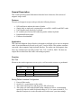
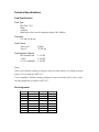
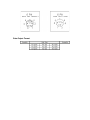
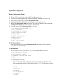
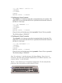
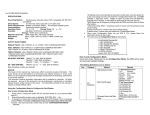
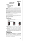
Universal
Magnetic Stripe Card Reader
Keyboard Interface
User’s Manual
ZBA Inc
94 Old Camplain Road
Hillsborough NJ 08844
Phone: 908-359-2070
Fax: 908-359-1272
Web: http://www.zbausa.com/
NOTICE
The issuer of this manual has made every effort to provide accurate information
contained in this manual. The issuer shall not be held liable for any technical and editorial
omissions or errors made herein; nor for incidental consequential damages resulting from
the furnishing, performance or use of this material. This document contains proprietary
information protected by copyright. All rights are reserved. No part of this document may
be photocopied, reproduced, or translated without the prior written permission of the
issuer. The information provided in this manual is subject to change without notice.
AGENCY APPROVED
This equipment had been tested and found to comply with the limits for a Class A digital
device, pursuant to part 15 of the FCC rules. These limits are designed to provide
reasonable protection against harmful interference when the equipment is operated in a
commercial environment. This equipment generates, uses, and can radiate radio
frequency energy and, if not installed and used in accordance with the instructions, may
cause harmful interference to radio communications. However, there is no guarantee that
interference will not occur in a particular installation. Operation of this equipment in a
residential area is also likely to cause harmful interference in which case the user will be
required to correct the interference at his own expense. This product also had been tested
and found to comply with the agency requirements of specification for CE mark Class A
and UL, cUL.
WARNING
You are cautioned that changes or modifications not expressly approved by the party
responsible for compliance could void your authority to operate the equipment.
WARRANTY
This product is served under one-year warranty of defects in material and functionality to
the original purchasers. Within the warranty period, if the product found to be defective
will be repaired or replaced. This warranty applies to the products only under the normal
use of the original purchasers, and in no circumstances covers incidental or consequential
damages through consumers’ misuse or modification of the product.
PREFACE
This manual provides detailed information relating to the overall operational, electrical,
mechanical, environmental and functional aspects of the universal magnetic stripe reader.
This document should be read and understood prior to initial operation of the product.
For ease of installation and programming use, we have addressed everything from its
attractive features to its various configurations. If further questions do arise, please call
for technical support.
INSTALLATION
To install the universal magnetic stripe reader with keyboard interface, please follow
these simple steps:
1. turn off PC
2. unplug keyboard from the PC
3. plug the universal magnetic stripe reader cable into the keyboard port (where you
removed the keyboard plug)
4. connect the keyboard plug to the other end of the card reader cable
5. turn on PC
Note: If you are using a USB keyboard or the universal magnetic stripe reader is
connected to a laptop computer, please skip steps 2 and 4.
Table of Contents
General Description........................................................................................................................................ 5
Features ...................................................................................................................................................... 5
Application ................................................................................................................................................. 5
Function...................................................................................................................................................... 5
Self Test.................................................................................................................................................. 5
Setting Default Interface Configuration ................................................................................................. 5
Technical Specifications................................................................................................................................. 6
Card Specifications..................................................................................................................................... 6
Card Type ............................................................................................................................................... 6
Thickness................................................................................................................................................ 6
Card Format............................................................................................................................................ 6
Card Operation Speed............................................................................................................................. 6
Pin Assignment........................................................................................................................................... 6
Data Output Format.................................................................................................................................... 7
Operation Sequence........................................................................................................................................ 8
Enter Configuration Mode.......................................................................................................................... 8
0: Exit Setup Mode ............................................................................................................................... 8
1: Set Interface...................................................................................................................................... 8
1: Set Keyboard Country ........................................................................................................................ 8
2: Set Transmit Speed............................................................................................................................. 9
3: Firmware Version and Date................................................................................................................ 9
2: Set Magnetic String.......................................................................................................................... 9
1: Set Enable Tracks............................................................................................................................... 9
2: Set Require Tracks ........................................................................................................................... 10
3: Carriage Return ................................................................................................................................ 10
4: Set SS/ES Send or Not ..................................................................................................................... 10
5: Caps Lock......................................................................................................................................... 11
6: Track Output Order .......................................................................................................................... 11
7: Change Carriage Return Code.......................................................................................................... 11
8: No Data Output ................................................................................................................................ 11
3: Set String Editing ........................................................................................................................... 12
1: Set Prefix .......................................................................................................................................... 12
2: Set Suffix.......................................................................................................................................... 12
3: Set Magnetic Stripe Preamble .......................................................................................................... 13
4: Set Magnetic Stripe Postamble......................................................................................................... 13
5: Block Output Order .......................................................................................................................... 14
6: Send Control..................................................................................................................................... 14
7: Field Output Order ........................................................................................................................... 15
8: Exp Date Format .............................................................................................................................. 16
9: Exp Date Separator........................................................................................................................... 16
4: Set Buzzer ....................................................................................................................................... 16
5: Reset to Default .............................................................................................................................. 16
6: Show Status..................................................................................................................................... 16
7: Diagnostic........................................................................................................................................ 17
1: RAM Test......................................................................................................................................... 17
2: ROM Checksum ............................................................................................................................... 18
3: LED Test .......................................................................................................................................... 18
4: Buzzer Test....................................................................................................................................... 18
5: Firmware Version and Date.............................................................................................................. 18
General Description
This section presents general information about the basic characters of the universal
magnetic stripe reader.
Features
The universal magnetic stripe reader provides the following features:
•
•
•
•
•
•
LED and Buzzer indicate the status of reader
Single, dual, or triple track versions allow to read ISO, AAMVA and DMV cards
User-friendly setup directly by keyboard
PC could be powered on with connecting reader without keyboard
Programmable data output
Firmware downloadable
Application
This Universal Magnetic Stripe Reader is designed to read high or low coercive magnetic
cards. It can simultaneously decode/verify up to 3 tracks of data. This product communicates with a host computer using keyboard interface. The reader can read magnetic data
form, any available track encoded per ISO 7810, 7811, AAMVA, DMV. The host can
request the read data from the reader with setting sequences.
Function
Self Test
Whenever the reader experiences a reset cycle, a self-test on the resources is performed.
Indication
LED
Buzzer
Green
Red
Orange
Green
1 Beep
2 Beeps
Cause
Test Success
EEPROM Failed
Internal ROM Failed
Default configuration working
Setting Default Interface Configuration
1. Power off the reader.
2. Switch S1_1 on and power on the reader.
3. The reader will beep twice and the green LED will turn on.
4. The reader will work under default setting condition as below: a) transmitting
speed is 80 char/sec, and b) keyboard country is U.S. As soon as switch S1_1 is
turned off and power is reset, the reader will work as user’s previous settings.
Technical Specifications
Card Specifications
Card Type
ISO 7810, 7811
DMV
AAMVA
Read high or low coercive magnetic stripes (300 -4000oe)
Thickness
0.76 mm ±0.08 mm
Card Format
Track 1 & 3:
Track 2:
210 bpi
75/210 bpi
Card Operation Speed
ISO standard card
* Jitter
** Low Amplitude
5~55 IPS
5~50 IPS
5~50 IPS
Notes:
*Jitter card: Reliable reading of magnetic stripes encoded with bit cell length variations
within ±15% as defined in ISO 7811.
** Low amplitude: Reliable reading of magnetic stripes encoded at 60% or more of the
encoding amplitude as defined in ISO 7811.
Pin Assignment
PCB-JP2
SIGNAL
PLUG
SOCKET
1
2
3
VCC
P-DATA
5
2
5
4
K-DATA
5
P-CLOCK
6
K-CLOCK
7
SHIELD
8
GND
2
1
1
4
4
Data Output Format
Operation Sequence
Enter Configuration Mode
1.
2.
3.
4.
5.
Power off PC, connect the reader with PC and then power on.
Execute text editor program such as Microsoft Word, Notepad, PE2, Edit…etc.
Press [Ctrl]+[Alt]+[F10] to enter Configuration Mode.
Operating step-by-step following instructions as shown on the screen.
While in Configuration Mode, the green LED is always blinking. After exiting the
Configuration Mode, the reader will reset automatically.
6. The main menu of Configuration Mode is as below:
**** CONFIGURATION MODE ****
1:SET INTERFACE
2:SET MAGNETIC STRING
3:SET STRING EDITING
4:SET BUZZER
5:RESET TO DEFAULT
6:SHOW STATUS
7:DIAGNOSTIC
0:EXIT SETUP MODE
0: Exit Setup Mode
Once user choose “0” to exit Configuration Mode, the reader will be reset and
execute the modified settings.
1: Set Interface
In the main menu, user could choose “1” to enter Set Interface sub-menu.
1:SET KEYBOARD COUNTRY
2:SET TRANSMIT SPEED
3:FIRMWARE VERSION AND DATE
0:BACK
1: Set Keyboard Country
This is used to inform the reader about the keyboard type that should be used
when transmitting card data. The default setting is “U.S.”. It will shown as below:
1:U.S.
2:DEUTSCH
3:FRENCH
4:U.K. ENGLISH
5:SPANISH
6:ITALY
7:DUTCH
8:PORTUGUESE
9:SWEDISH
0:BACK
READER STATUS = U.S.
READER STATUS displays the country of keyboard interface in use. The user
could choose 1~9 to change the keyboard interface. Choose “0” to return to last
menu.
2: Set Transmit Speed
This is used to set the speed of card data sent to the host. The default setting is 80
characters/sec. It will be shown as below:
**** SET TRANSMIT SPEED ****
1:25 CHARACTER/SEC
2:40 CHARACTER/SEC
3:60 CHARACTER/SEC
4:80 CHARACTER/SEC
5:120 CHARACTER/SEC
0:BACK
READER STATUS = 80 CHAR/SEC
3: Firmware Version and Date
Display the firmware version and release date. The message is shown as below:
2100121A ROBIN MAR-13-2001
where 2100121A represents the version of the firmware.
2: Set Magnetic String
In the main menu, user could choose “2” to enter Set Magnetic String sub-menu.
1:SET ENABLE TRACKS
2:SET REQUIRE TRACKS
3:CARRIAGE RETURN
4:TRANSMIT SS/ES
5:CAPS LOCK
6:TRACK OUTPUT ORDER
7:CHANGE CARRIAGE RETURN CODE
8:NO DATA OUTPUT
0:BACK
1: Set Enable Tracks
This function is used to enable and disable specific tracks of data sent from the
reader. The default setting is “TRACK 1, 2, 3”. For example, for a triple track
reader it may be necessary in some applications to use only Track 2 data. In this
case, this setting can make Track 2 enabled and disable Track 1&3.
**** ENABLE TRACKS ****
1:TRACK 1
2:TRACK 2
3:TRACK 1,2
4:TRACK 3
5:TRACK 1,3
6:TRACK 2,3
7:TRACK 1,2,3
0:BACK
READER STATUS = TRACK 1,2,3
2: Set Require Tracks
This function is used to set Require Track as criteria of successful reading. The
default setting is “ANY TRACK”. The criteria means if the Require Track has
been read after swiping card. For example, if user sets Track 2 as a criterion and
gets Track 2 data exactly from the reading a card, then it is a good read and the
reader sends all enabled track data to the host. If not, the reader doesn’t transmit
any data. The default setting is “any track will be considered a good read”. This
feature is useful if your software requires specific tracks of the card data.
**** SET REQUIRE TRACKS ****
1:TRACK 1
2:TRACK 2
3:TRACK 1,2
4:TRACK 3
5:TRACK 1,3
6:TRACK 2,3
7:TRACK 1,2,3
8:ANY TRACK
0:BACK
READER STATUS = ANY TRACK
3: Carriage Return
This is used to set the output data with or without Carriage Return for each
track. The default setting is “AFTER EACH TRACK”.
**** CARRIAGE RETURN ****
1:DON'T SEND CARRIAGE RETURN
2:AFTER ALL TRACKS
3:AFTER EACH TRACK
4:AFTER ALL DATA
0:BACK
READER STATUS = AFTER EACH TRACK
4: Set SS/ES Send or Not
This function is used to determine whether the SS and ES of each track will be
sent with the card data. The default setting is “ENABLE”. (SS: start sentinel;
ES: end sentinel)
**** SS/ES SEND ****
1:SEND
2:NO SEND
0:BACK
READER STATUS = ENABLE
5: Caps Lock
This function is used to send data as capital letters. The default setting is
“ENABLE”. No matter whether Caps Lock on the keyboard is ON or OFF, the
reader is always sending out capital letters while the setting is “ENABLE”. Once
this setting is “DISABLE”, the letters of the sent data are consistent with the Caps
Lock status. The default setting is “ENABLE”.
1:ENABLE
2:DISABLE
0:BACK
READER STATUS = ENABLE
6: Track Output Order
The Track Output Order is used to control the order of each track output. The
default setting is “1, 2, 3”. You have to input the track in order; i.e.: FIRST,
SECOND, and then THIRD.
1:TRACK 1
2:TRACK 2
3:TRACK 3
0:BACK
READER STATUS = 1,2,3
FIRST:
7: Change Carriage Return Code
The Change Carriage Return Code is used to change the code of carriage return.
The default setting is [ENTER].
1:CHANGE
2:RESET
0:BACK
READER STATUS = [ENTER]
8: No Data Output
The default setting is “DISABLE”.
NO DATA OUTPUT CARRIAGE RETURN
1:ENABLE
2:DISABLE
0:BACK
READER STATUS = DISABLE
3: Set String Editing
In the main menu, select “3” to enter Set String Editing sub-menu.
1:SET PREFIX
2:SET SUFFIX
3:SET MAGNETIC STRIPE PREAMBLE
4:SET MAGNETIC STRIPE POSTAMBLE
5:BLOCK OUTPUT ORDER
6:SEND CONTROL
7:FIELD OUTPUT ORDER
8:EXP DATE FORMAT
9:EXP DATE SEPARATOR
0:BACK
1: Set Prefix
The track 1, 2, 3 prefixes are 6-character strings that are transmitted prior to the
track data. It will be shown as below:
1:TRACK 1
2:TRACK 2
3:TRACK 3
0:BACK
After selecting track, user sets the prefix for the specified track. If track needs
prefix, choose 1 and key-in 1~6 characters for the prefix; otherwise choose 2.
The default setting is “DISABLE”.
**** SET TRACK 1 PREFIX ****
1:ENABLE
2:DISABLE
0:BACK
READER STATUS = DISABLE
2: Set Suffix
The track 1, 2, 3 suffixes are 6-character strings that are transmitted after to the
track data. It will be shown as below:
1:TRACK 1
2:TRACK 2
3:TRACK 3
0:BACK
After selecting track, user sets the suffix for the specified track. If track needs
suffix, choose 1 and key-in 1~6 characters for the suffix; otherwise choose 2.
The default setting is “DISABLE”.
**** SET TRACK 1 SUFFIX ****
1:ENABLE
2:DISABLE
0:BACK
READER STATUS = DISABLE
3: Set Magnetic Stripe Preamble
The preamble is a 6-character string that is transmitted before all card data. This
string allows you to ensure that the cursor is positioned at the desired location at
the time of a card swipe.
**** SET PREAMBLE ****
1:ENABLE
2:DISABLE
0:BACK
READER STATUS = DISABLE
Choose 1 to key-in 1~6 characters for the preamble. Choose 2 for no preamble.
The default setting is “DISABLE”.
4: Set Magnetic Stripe Postamble
The postamble is a 6-character string that is transmitted after all card data. This
string allows you to ensure that the cursor is positioned at the desired location at
the time of a card swipe.
**** SET POSTAMBLE ****
1:ENABLE
2:DISABLE
0:BACK
READER STATUS = DISABLE
Choose 1 to key-in 1~6 characters for the postamble. Choose 2 for no postamble.
The default setting is “DISABLE”.
Note: For selections 1~4 in this sub-menu (Set String Editing): If user keys in 6
characters, this mode will be finished automatically, if less than 6 characters, user
can press the key ` to end this mode.
The key ` is the character for U.S. keyboard configuration. For the same function,
please press the exact position on the keyboard as below.
5: Block Output Order
The Block Output Order is used to control the order and appearance of each block
output. Each track has three blocks (A, B, C) which could be set conforming to
ISO, DMV or AAMVA, and the characters of each block could be set during
1~109. Example: Controlling the output data format of block A on track 1 is ISO
standard card, 15th character to 30th character. The procedure is as follows:
Step 1: Choosing 1 to set data format of TRACK 1.
**** SET BLOCK OUTPUT ORDER ****
1:TRACK 1
2:TRACK 2
3:TRACK 3
0:BACK
Step 2: Choosing 1 to set BLOCK A.
1:BLOCK A
2:BLOCK B
3:BLOCK C
0:BACK
Step 3: Choosing 3 to set the card type to ISO standard.
** SET TRACK1 BLOCK A **
READER STATUS = DISABLE
1:DMV
2:AAMVA
3:ISO
9:DISABLE
0:BACK
Step 4: To set the range of the transmitting data format.
START = 15
END = 30
6: Send Control
This function is used to control the reader send out data until users press a specific
key or any key after swiping cards. After choosing 1 and a beep sound, a user
starts to set the key, which will become to control the send data. That means the
reader will not send data until users press the exact key. If choose 2, the reader
will send data once pressing any key excluding extension key(s). The default
setting is “DISABLE”.
1:SET KEY
2:ANY KEY
3:DISABLE
0:BACK
READER STATUS = DISABLE
7: Field Output Order
The Field Output Order is used to control the order and appearance of each field
output. Each card has three fields could be set (i.e.: Name, Account, and Expire
Date). You may set one, two, or three fields that depend on actual application.
The default setting is “DISABLE”.
1:ENABLE
2:DISABLE
0:BACK
READER STATUS = DISABLE
Step 1: Choosing 1 to enable field output order.
1:NAME
2:ACCOUNT
3:EXPIRE DATE
0:BACK
FIRST:
Example: Setting the Field Output Order as Expire Date, Name, and Account in
order. The procedure is as follows:
Step 1: Choosing 1 to enable field output order.
1:NAME
2:ACCOUNT
3:EXPIRE DATE
0:BACK
FIRST:
Step 2: Key in 3 to choose Expire Date as the first output field.
FIRST: 3
SECOND:
Step 3: Key in 1 to choose Name as the second output field.
FIRST: 3
SECOND: 1
THRID:
Step 4: Key in 2 to choose Account as the third output field.
After setting done, you may re-confirm it by entering “Field Output Setting”
section. You shall see:
1:ENABLE
2:DISABLE
0:BACK
READER STATUS = EXPIRE DATE,NAME,ACCOUNT
8: Exp Date Format
The Expire Date Format is used to set the format of expiration date of the Field
Output Order. This function only is effective while Field Output Order is enabled,
and will not effect general card data output. The default setting is “YYMM”.
1:YYMM
2:MMYY
0:BACK
READER STATUS = YYMM
9: Exp Date Separator
The Expire Date Separator is used to set a specific character to separate the MM
and YY that is defined in Expire Date Format. This function only is effective
while Field Output Order is enabled, and will not effect general card data output.
The default setting is “DISABLE”.
1:CHANGE
2:RESET
0:BACK
READER STATUS = DISABLE
4: Set Buzzer
In the main menu, choose 4 to enter “Set Buzzer” mode. Select 1 to make the Buzzer
of the reader active, or 2 to make Buzzer of the reader inactive. This function only is
effective while swiping card. The default setting is “ENABLE”.
**** SET BUZZER ENABLE/DISABLE ****
1:ENABLE
2:DISABLE
0:BACK
READER STATUS = ENABLE
5: Reset to Default
In the main menu, choose 5 to enter “Reset to Default” mode. Select 1 to reset to
default and return the unit to initial factory settings.
1:RESET TO DEFAULT
0:BACK
6: Show Status
In the main menu, choose 6 to display the current settings of the reader.
For example:
KEYBOARD COUNTRY=U.S
TRANSMIT SPEED=80 CHAR/SEC
ENABLE TRACKS=TRACK 1,2,3
REQUIRE TRACKS=ANY TRACK
CARRIAGE RETURN=AFTER EACH TRACK
SS/ES SEND=ENABLE
CAPS LOCK=ENABLE
BUZZER=ENABLE
DATA OUTPUT=1,2,3
PRESS 0 TO BACK
Press any key to check other settings of the reader, or press 0 to exit “Show Status”
mode and return to main menu.
TRACK 1 PREFIX=DISABLE
TRACK 2 PREFIX=DISABLE
TRACK 3 PREFIX=DISABLE
TRACK 1 SUFFIX=DISABLE
TRACK 2 SUFFIX=DISABLE
TRACK 3 SUFFIX=DISABLE
PREAMBLE=DISABLE
POSTAMBLE=DISABLE
PRESS 0 TO BACK
Press any key to check other settings of the reader, or press 0 to exit “Show Status”
mode and return to main menu.
TRACK1
TRACK1
TRACK1
TRACK2
TRACK2
TRACK2
TRACK3
TRACK3
TRACK3
BLOCK
BLOCK
BLOCK
BLOCK
BLOCK
BLOCK
BLOCK
BLOCK
BLOCK
A=DISABLE
B=DISABLE
C=DISABLE
A=DISABLE
B=DISABLE
C=DISABLE
A=DISABLE
B=DISABLE
C=DISABLE
After showing all of the settings, press any key to back to the main menu.
7: Diagnostic
In the main menu, choose 7 to enter “Diagnostic” sub-menu.
1:RAM TEST
2:ROM CKECKSUM
3:LED TEST
4:BUZZER TEST
5:FIRMWARE VERSION AND DATE
0:BACK
1: RAM Test
This is used to perform RAM test. When user chooses this function in
“Diagnostic” sub-menu, the reader will start RAM test. The messages that
indicate the test result are shown below:
RAM TEST START
RAM TEST OK
or
RAM TEST START
RAM TEST FAIL
2: ROM Checksum
This is used to request ROM checksum from reader. When user chooses this
function in “Diagnostic” sub-menu, the reader will response with the checksum
as shown below:
CHECKSUM XXXX
where XXXX represents the checksum of the ROM.
3: LED Test
Perform LED test. When user chooses this function in “Diagnostic” sub-menu,
the reader LED will turn off, green, red, and orange in this order. Then it will
return to previous status (green blinking). The message is shown as below:
LED TEST START
LED TEST END
4: Buzzer Test
This is used to perform BUZZER test. When user chooses this function in
“Diagnostic” sub-menu, the reader will beep long once. The message is shown as
below:
BUZZER TEST START
BUZZER TEST END
5: Firmware Version and Date
Display the firmware version and release date. The message is shown as below:
2100121A ROBIN MAR-13-2001
where 2100121A represents the version of the firmware.