1
Z-3080
CCD Barcode Scanner
Multi-Interface
User’s Manual
ZBA Inc
249 Homestead Rd Unit 12
Hillsborough NJ 08844
Phone: 908-359-2070
Fax: 908-359-1272
Web: http://www.zbausa.com/
NOTICE
The issuer of this manual has made every effort to provide accurate information contained in this
manual. The issuer shall not be held liable for any technical and editorial omissions or errors
made herein; nor for incidental consequential damages resulting from the furnishing, performance
or use of this material. This document contains proprietary information protected by copyright.
All rights are reserved. No part of this document may be photocopied, reproduced, or translated
without the prior written permission of the issuer. The information provided in this manual is
subject to change without notice.
AGENCY APPROVED
This equipment had been tested and found to comply with the limits for a Class A digital device,
pursuant to part 15 of the FCC rules. These limits are designed to provide reasonable protection
against harmful interference when the equipment is operated in a commercial environment. This
equipment generates, uses, and can radiate radio frequency energy and, if not installed and used in
accordance with the instructions, may cause harmful interference to radio communications.
However, there is no guarantee that interference will not occur in a particular installation.
Operation of this equipment in a residential area is also likely to cause harmful interference in
which case the user will be required to correct the interference at his own expense.
WARNING
You are cautioned that changes or modifications not expressly approved by the party responsible
for compliance could void your authority to operate the equipment.
WARRANTY
This product is served under one-year warranty of defects in material and functionality to the
original purchasers. Within the warranty period, if the product found to be defective will be
repaired or replaced. This warranty applies to the products only under the normal use of the
original purchasers, and in no circumstances covers incidental or consequential damages through
consumers’ misuse or modification of the product.
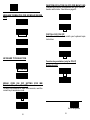
INSTALLATION
Keyboard Wedge
1.
2.
3.
4.
5.
Turn off the PC
Disconnect the keyboard cable from the PC.
Connect the Keyboard Cable to the scanner and connect the scanner cable to the PC
Turn the terminal/computer power on.
You are ready use the scanner
RS-232
1.
2.
3.
4.
5.
Turn off the PC.
Connect the Scanner cable to the PC.
Plug the power supply to the scanner
Plug the power pack into power source.
Turn on PC, You are ready to use the scanner
USB (with HID Keyboard Interface)
1. Plug the USB cable to PC. (some USB hub may have power problem, Check with HUB
manufacturer)
2. Follow the instruction to install windows driver come with your windows operating system.
Note: The scanner may not work with windows 95 or windows 98 first edition.
TABLE OF CONTENTS
Introduction......................................................... 1
Default Parameters ............................................. 2
Program Procedure............................................. 5
System Setting ................................................... 6
General Configuration
Scanning Mode Selection.................................... 9
Inter- Message Delay ........................................ 10
Inter- Character Delay....................................... 11
Message/ Block Mode Selection........................ 11
Beeper Tone Selection ...................................... 12
Interface Configuration
RS-232C Serial Communication Parameters Setting
Handshaking Protocol............................... 15
ACK/ NAK Response Time Setting ............ 16
Baud Rate ................................................ 16
Data Bit .................................................... 17
Stop Bit .................................................... 17
Parity Setting ............................................ 17
Message Terminator ................................. 18
Keyboard Emulation Parameters Setting............ 19
Keyboard Type Selection .......................... 19
Language Selection .................................. 21
Message Terminator ................................. 22
Function Key Emulation ............................ 23
Capital Lock Setting .................................. 23
Wand Emulation Parameters Setting ................. 24
Emulation Data Output Selection............... 25
Wand Emulation Narrow/Wide Ratio.......... 25
Cursor Pad Work at Numlock .................... 25
USB Interface Parameters Setting ..................... 26
Keyboard Type ......................................... 26
Message Terminator ................................. 26
The Symbologies
Reading Code Selection.................................... 28
Code 39 Parameters Setting ............................. 30
Interleaved 2 Of 5 Parameters Setting ............... 31
i
Chinese Post Code Parameters Setting..............32
UPC/ EAN/ JAN Parameters Setting ..................33
Coda bar/ Monarch Parameters Setting..............37
Code 128 Parameters Setting ............................37
MATRIX 25 Parameters setting ..........................38
MSI/Plessy parameters setting...........................39
Italian Pharmacy Parameters Setting .................40
Barcode Length Setting .....................................41
ISBN/ ISSN Conversion .....................................42
Data Editing
Header and Trailer.............................................43
Barcode Identifier Code Selection ......................44
Barcode Identifier Code Setting..........................45
Truncate Header/Trailer Character .....................47
Appendixes
Appendix A
Code 39 Full ASCII Code Table..................49
Appendix B
Code 39 Full ASCII Bar Code Table ...........52
Appendix C
Barcode Samples ......................................62
Appendix D
Quick Settings...........................................63
1. INTRODUCTION
Scanning a series of programming bar code labels can
configure the series scanners. This allows decoding
options and interface protocols to be tailored to a
specific application. The configuration is stored in
non-volatile memory and will not be lost by removing
power from the scanner.
The scanner must be properly powered before
programming. For RS-232C type scanners, an external
power adapter must be used to supply DC power to the
scanner. If a keyboard emulation type scanner is used
with an IBM PC/XT/AT, PS/2 or any fully compatible
computers, power will be drawn from the keyboard port.
No external power adapter is required. If keyboard
emulation type scanner is used with any other non IBM
PC compatible computers, an external power adapter
may be needed.
During the programming mode, the laser scanner will
acknowledge a good and valid reading with a short beep.
It will give long beeps for either an invalid or bad
reading.
2. PROGRAMMING OPTIONS
Programmable options are divided into four groups.
The first group includes the options that show the
general behavior of the laser scanner. The second
group of options governs the operation of RS-232C type
serial ports. The third group selects the keyboard type
that the keyboard emulation type will be emulated. The
last group sets the decoding parameters for each
barcode symbology.
ii
1
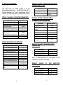
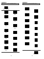
3. DEFAULT PARAMETERS
DEFAULT VALUES OF KEYBOARD EMULATION
PARAMETERS SETTING
This table gives the default settings of all the
programmable parameters. The default settings will be
restored whenever the "Reset" programming label is
scanned and the laser scanner is in programming mode.
DEFAULT VALUES OF OPERATING PARAMETERS
Function
Scanning Mode Selection
Header and trailer
Inter-Message delay
Inter-Character delay
Message/Block mode selection
Send command in block mode
communication
Good read beeper tone selection
Code identifier transmitting
Default Values
Trigger mode
None
Normal
Normal
Message
Function
Default Values
Keyboard type selection
Message terminator
IBM PC/AT USA
Enter/ carriage
Return
DEFAULT VALUES OF RS-232C SERIAL
COMMUNICATION PARAMETERS
Function
Default Values
Handshaking protocol
ACK/NAK response time
setting
Baud rate
Disable
Data bit
Medium
Disable
Stop bit
None
300 msec
9600
8
1
Parity
Message terminator
selection
Mark
CR/LF
*
PREDEFINED BARCODE IDENTIFIERS
Code 39 barcode identifier code
ITF 2 of 5 barcode identifier code
Chinese post code identifier code
UPC-E barcode identifier code
UPC-A barcode identifier code
EAN-13 barcode identifier code
EAN-8 barcode identifier code
Codabar barcode identifier code
Code 128 barcode identifier code
Code 93 barcode identifier code
MSI barcode identifier code
MATRIX 25 barcode identifier
code
M
I
H
E
A
F
FF
N
K
L
P
DEFAULT VALUES OF WAND EMULATION
PARAMETERS
Function
Default Values
¡ °Wand emulation speed
¡ °Wand emulation output
Normal
Black = High
Note: For wand emulation, the configuration is only
effective for the items with asterisk (¡ )°
.
DEFAULT
VALUES
PARAMETERS
OF
Default Values
°Keyboard Type
¡
¡ °Message Terminator
2
EMULATION
G
Function
*
USB
US Keyboard
Enter
3
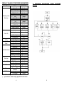
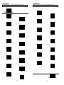
DEFAULT VALUES OF DECODING PARAMETERS
Function
Code
Code 39
ITF 2 of 5
Chinese Post Code
UPC/EAN/JAN
Coda bar
Reading codes ¡ °
MSI
Selection
Code 128
Code 93
¡ °
ITAT
¡ ° EAN-128
¡ ° MATRIX 25
¡ °
Italian Pharmacy
ISSN/ ISBN
Codes
Start/stop characters
Code 39
Check digit
Concatenation
Interleaved
Length
2 of 5
Check digit
Chinese Post
Length
Code
Check digit
Format
Addendum
UPC-E=UPC-A
UPC/EAN/JAN
UPC-A leading digit
UPC-A check digit
UPC-E leading digit
UPC-E check digit
Type
Coda bar
Start/stop characters
Length
Code 128
FNC 2 append
Check digit
MSI
Length
Check digit
Italian Pharmacy
Transmit "A"
Character
MATRIX 25
Length
Check digit
Default Value
4. PROGRAM
MENUS
PROCEDURE
Enable
Enable
Disable
Enable
Enable
Disable
Enable
Enable
Disable
Disable
Disable
Disable
Disable
Standard
Not transmitting
Disabled
Off
6-32 digits
Disable
10~16 digits
Transmit
All
Disable
Disabled
Transmit
Transmit
Transmit
Transmit
Standard
A, B, C, D
6~32 digits
Disable
Disable
Variable
Transmit
Not transmitting
NO
YES
NO
YES
Fix 10 digits
Disable
Note: The configuration of the items with asterisk
(¡ )°is effective when being appointed in advance.
4
5
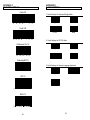
USING
BARCODE
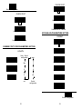
Start of Configuration
RESET
Ÿ The reading of the "RESET”
label
turns
all
the
parameters back to default
values.
Ÿ When you intend to turn
your scanner back to
default parameter, please
scans
the
"Start
of
configuration" label first,
then scan "RESET" label
• The reading of the "ABORT"
label
ABORT
discards
all
the
parameters read prior to the
"End of configuration".
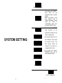
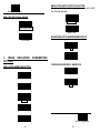
SYSTEM SETTING
RS-232C
• The scanner remains in the
last interface mode when
the scanner is reset.
PC/AT
label
below
should
The
be
scanned if the scanner is
configured the first time.
USB
l The reading of the “SHOW
VERSION” label will
show firmware version.
WAND EMULATION
SHOW VERSION
End of Configuration
6
7
be
Start of Configuration
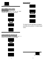
SCANNING MODE SELECTION (for laser scanner)
For series laser scanners, there are 3 scanning modes to suit
your application requirements.
The scanner becomes inactive
as soon as the data is
transmitted.
It must be
triggered to become active
Trigger Mode
again.
Pulse Mode
GENERAL
CONFIGURATION
The scanner will light up when
press the pulse mode trigger
switch once.
And, the
scanner will turn off for next
pressing.
SCANNING MODE SELECTION (For CCD scanner)
The scanner becomes inactive as
soon as the data is transmitted. It
must be triggered to become
active again.
In auto scan mode, the scanner is
still active after the data is
transmitted, but the successive
transmission of the same bar code
is not allowed when the trigger
switch is pressed again.
This scanner will light up when
press the scanner trigger switch
once. And, the scanner will turn
off for next pressing.
This mode is similar to Auto scan
mode, but double reading for the
same barcode is prohibited if the
scanner switch is pressed.
Trigger mode
Auto scan mode
Alternate mode
Repeat mode
End of Configuration
8
9
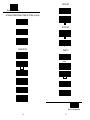
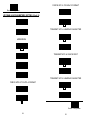
INTER-CHARACTER DELAY
This option governs delay time between consecutive
characters. Scanning the following labels can alter the
delay time.
Start of Configuration
DATA REDUNDANT CHECK
The option allows you to set
decoder
data
redundant
check.
None
Enable
10 msec
Disable
20 msec
INTER-MESSAGE DELAY
These series of scanners allow you to add a delay
between two consecutive messages. This delay will be
added before each data transmission.
None
100 msec
500 msec
1 Second
50 msec
MESSAGE/BLOCK MODE SELECTION
This option allows you to treat scanned data as either an
independent message or a block message. In the
message mode, the data scanned will be transmitted
immediately. In block mode, the data scanned will be
appended to the message buffer if the scanner is
programmed in block mode. A block of message will
only be transmitted after a “Send” command is entered.
This mode is only available when the scanner is working
with code 39 labels. You are free to choose any
character as the “ Send” command.
Message
Block
End of Configuration
10
11
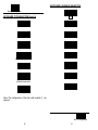
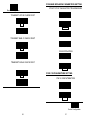
SOUND DURATION
Start of Configuration
long(120 ms)
SEND COMMAND IN BLOCK MODE
COMMUNICATION
You can use this option to set your own “Sen d”
command used in block mode communication.
Medium(50 ms)
Enable
Short(20 ms)
Disable
Very short(5 ms)
Store
*For Alpha-70 and SC-2070 Series only Medium
and disable setting available, it’s hardware beeper
control.
Set
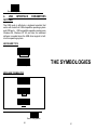
GOOD READ BEEPER TONE SELECTION
You can use this option to set frequency and / or
duration of the buzzer after successful reading.
Medium
Low
High
End of Configuration
Disable
12
13
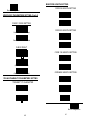
Start of Configuration
1. RS-232C SERIAL COMMUNICATION
PARAMETERS SETTING
The RS-232C scanner supports four handshaking
protocols. With these options of communication protocol,
you can tailor the scanner to meet the requirement of
most systems
HANDSHAKING PROTOCOL
None
RTS/CTS
INTERFACE
CONFIGURATION
ACK/NAK
Xon/Xoff
ACK/NAK RESPONSE TIME SETTING
300 msec
2 sec
500 msec
End of Configuration
14
15
DATA BIT
Start of Configuration
ACK/NAK RESPONSE TIME SETTING (Cont’d)
7
8
3 sec
STOP BIT
1 sec
1
5 sec
2
BAUD RATE
PARITY
19200
Even
9600
Odd
4800
Mark
2400
Space
1200
None
600
End of Configuration
16
17
2. KEYBOARD EMULATION PARAMETERS
SETTING
Start of Configuration
MESSAGE
ONLY)
TERMINATOR
None
CR/LF
CR
LF
H Tab
STX/ETX
EOT
(FOR
RS-232C
TYPE
KEYBOARD TYPE SELECTION
The keyboard emulation scanners can emulate a number of
personal computers keyboard and a number of terminal
keyboard. Keyboard emulation is activated whenever you have
selected the type of keyboard for which the scanner is going to
emulate. Choose the appropriate type of keyboard emulation by
scanning the labels under the following labels.
IBM AT
PS/2 30-80
IBM 5550
IBM 5295 Terminal
IBM XT
IBM 5530-SC
IBM 5530-ZC
End of Configuration
18
19
KEYBOARD LANGUAGE SELECTION
Start of Configuration
KEYBOARD TYPE SELECTION (Cont’d)
NEC 9801
USA
UK
IBM 3196 Terminal
APPLE MAC II(¡ °
)
French
IBM 3477/3472 Terminal
Spanish
PS2/30/56
Italian
IBM 3477 Terminal
(Without break code)
Swiss
Swedish
NEC 5200(¡ °
)
Note: The configuration of the items with asterisk (¡ °
) is
optional.
End of Configuration
20
21
FUNCTION KEY ACTIVE ON/ OFF (FOR IBM AT USE)
Function keys can be concatenated with input data as
header and/or trailer. See table on page 40.
MESSAGE TERMINATOR (FOR KEYBOARD WEDGE
USE)
ON
None
OFF
Return /Enter
CAPITAL LOCK ON/ OFF
Select the suitable code to match your keyboard caps
lock status.
Hor. TAB
ON
Execute
OFF
KEYBOARD TYPE SELECTION
Function key emulation (only for PC/AT)
Numlock on/off
Scan Code Mode
OFF
Alt mode
BREAK CODE ON/ OFF SETTING (FOR IBM
Terminals 31xx, 34xx, 37xx USE)
To select the interface for these IBM terminals, read the
correct key transmission code.
ON
ON
OFF
22
End of Configuration
23
EMULATION DATA OUTPUT SELECTION
The decoded data output logic level can be set to befit
the external decoder.
Start of Configuration
00H~1FH ASCII Code defined
Black = High
Alt-mode code
Black = Low
WAND EMULATION NARROW/WIDE RATIO
Crtl+code
1:2
3. WAND
SETTING
EMULATION
EMULATION SPEED SELECTION
PARAMETERS
1:3
CURSOR PAD WORK AT NUMLOCK
ON
Low
OFF
Medium
Normal
High
End of Configuration
Higher
24
25
Start of Configuration
4.
USB
SETTING
INTERFACE
PARAMETERS
The USB mode is effectively a keyboard emulator that
works with hosts that USB-compatible operating system
and USB ports. USB compatible operating systems are
Windows 98, Windows NT 5.0 and later, no additional
software is needed since the USB driver support is built
into this operating system.
KEYBOARD TYPE
US Keyboard
International Keyboard
THE SYMBOLOGIES
MESSAGE TERMINATOR
None
Enter
H Tab
End of Configuration
26
27
Start of Configuration
Code 128 Disable
READING CODE SELECTION
MSI Enable
Code 39 Enable
MSI Disable
Code 39 Disable
Code 93 Enable
Coda bar Enable
Code 93 Disable
Coda bar Disable
IATA Enable
UPC/ EAN/ JAN Enable
IATA Disable
UPC/ EAN/ JAN Disable
EAN- 128 Enable
ITF 2 of 5 Enable
EAN-128 Disable
ITF 2 of 5 Disable
MATRIX 25 Enable
Chinese Post Code Enable
MATRIX Disable
Chinese Post Code Disable
End of Configuration
Code 128 Enable
28
29
Start of Configuration
NO
CONCATENATION
READING CODE SELECTION (Cont’d)
Enable
Italian Pharmacy Enable
Disable
Italian Pharmacy Disable
CODE 39 PARAMETERS SETTING
INTERLEAVED 2 OF 5 PARAMENTERS SETTING
Examples: Felting length 4 to 8 digits
LENTGTH
CHARACTER SET
Standard Code 39
Full ASCII Code 39
START/STOP CHARACTER TRANSMISSION
Scan:. Start of
configuration
max
Min
0
0
8
4
set
set
End of
configuration
MAX
Min
Set
Yes
No
CHECK DIGIT
Calculate and Transmit
End of Configuration
Calculate but not Transmit
30
31
CHECK DIGIT
Start of Configuration
NO
CHECK DIGIT
Calculate and Transmit
NO
Calculate but not Transmit
Calculate and Transmit
UPC/EAN/JAN PARAMETERS SETTING
FORMAT
Calculate but not Transmit
All
CHINESE POST CODE PARAMETERS SETTING
LENGTH
EAN-8 or EAN-13
Scan:. Start of
configuration
max
Min
0
0
8
MAX
UPC-A and EAN-13
UPC-A and UPC-E
MIN
Set
4
set
set
End of
configuration
UPC-A
UPC-E
End of Configuration
32
33
FORCE UPC-A TO EAN-13 FORMAT
Start of Configuration
UPC/EAN/JAN PARAMETERS SETTING (Cont’d)
Yes
EAN-13
No
TRANSMIT UPC-A LEADING CHARACTER
EAN-8
ADDENDUM
Yes
NO
No
TRANSMIT UPC-A CHECK DIGIT
5 Characters
Yes
2 Characters
No
2 or 5 Characters
TRANSMIT UPC-E LEADING CHARACTER
FORCE UPC-E TO UPC-A FORMAT
Yes
Yes
No
No
End of Configuration
34
35
CODABAR/ MONARCH PARAMETERS SETTING
START/ STOP CHARACTER TRANSMISSION
Start of Configuration
TRANSMIT UPC-E CHECK DIGIT
No
Yes
A, B, C, D
No
TRANSMIT EAN-13 CHECK DIGIT
DC1~DC4
a/ t, b/ n, c/ *, d/ e
Yes
CONCATENATION
No
Enable
TRANSMIT EAN-8 CHECK DIGIT
Disable
CODE 128 PARAMETERS SETTING
Yes
FNC 2 CONCATENATION
No
Enable
Disable
End of Configuration
36
37
MSI/PLESSY PARAMETERS SETTING
Examples: Felting length 4 to 8 characters
Start of Configuration
Scan:. Start
of
configuration
CODE 128 PARAMETERS SETTING (Cont’d)
0
MAX
CHECK DIGIT
max
Min
8
0
set
No
MIN
4
set
Calculate but not Transmit
End of
configuration
SET
Double Check digit
Calculate and Transmit
UCC/EAN128 PARAMETERS SETTING
The character FNC1 can be transmitted or not using
these codes.
Calculate but not Transmitted
FNC1 Character Transmitted
No
FNC1 not Transmitted
Calculate but only first one Transmitted
MATRIX 25 PARAMETERS SETTING
Examples: Felting length 4 to 8 characters
Scan. Start
of
configuration
Calculated and both Transmitted
max
Single Check digit
0
MAX
Min
8
Calculated but not Transmitted
0
set
MIN
4
set
End of
configuration
Calculated and transmitted
Set
End of Configuration
38
39
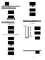
BARCODE LENGTH SETTING
CODE 39 LENGTH SETTING
Start of Configuration
MSI/PLESSY PARAMETERS SETTING (Cont’d)
MAX
PLESSY CODE SETTING
MIN
CODE 93 LENGTH SETTING
Calculated and transmitted
Calculate but not transmitted
CHECK DIGHT
MAX
MIN
CODE 128 LENGTH SETTING
No
MAX
Calculate and Transmit
MIN
Calculate but not Transmit
CODABAR LENGTH SETTING
ITALIAN PHARMACY PARAMETERS SETTING
TRANSMIT "A" CHARACTER
MAX
Yes
MIN
No
SET
End of Configuration
40
41
Start of Configuration
ISBN/ ISSN CONVERSION
The function convents the UPC/EAN codes appearing
on books and magazine not ISBN/ISSN format.
ACTIVE ISBN/ ISSN
INACTIVE ISBN/ ISSN
DATA EDITING
End of Configuration
42
43
Start of Configuration
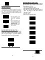
HEADER AND TRAILER
This option allows you to append a header and/or a trailer to
every message transmitted via the serial ports or the keyboard
port. There is no restriction in selecting header or trailer
characters as far as the sum of the lengths of header and trailer
is not greater than 10 digits.
Header
Trailer
1. Select either header or trailer
you are going to program by
scanning the corresponding
label
2. Scan the character(s) you want
from the enclosed ASCII table to
set as header or trailer (be sure
to enable full ASCII code 39
option before you start).
3. Read the “Set” label to set your
choice into memory.
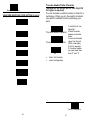
BARCODE IDENTIFIER CODE SETTING
Each of the series type scanners can set max.2 digits as
barcode identifier code according to different barcode.
The procedure is as follows:
1. Scan “Start of configuration” label
2. Scan “Barcode identifier setting code” label.
3. Scan the new code mark from ASCII table (max. two
digits). For example, if one “AB” want for code mark
then scan “A” and “B”.
4. Scan “Set” label.
5. Scan “ End of configuration” label.
UPC-E
UPC-A
Set
EAN-13
BARCODE IDENTIFIER CODE SELECTION
The series of scanners can transmit max.2-digit barcode
identifier code for different types of barcodes. Use the
labels to choose transmit or not transmit predefined
barcode identifier code (ID’s are listed on page 2):
EAN-8
Chinese post code
Enable
ITF 2 OF 5
Disable
End of Configuration
44
45
Start of Configuration
BARCODE IDENTIFIER CODE SETTING (Cont’d)
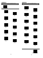
Truncate Header/Trailer Character
(Version az1.24, dz1.05, ac1.01, dz1.05,pl1.39
Or higher is required)
You can truncate a number header or trailer for a
symbology. When you do, the specific character
you select is deleted from the symbology you
want.
Coda bar
Truncate header character
Code 39
Truncate trailer character
Code 128
set
1.scan”start of con figuration”
2.select”truncate
header or truncate
trailer
3.scan two barcode
value from the full
ASCII code table(
0~9) For example,
if 2 number header
you want clear then
scan ”0” and “2”
Code 93
4.
5.
Scan” set” barcode
end of configuration
MSI
MATRIX 25
Set
End of Configuration
46
47
APPENDIX A
CODE 39 FULL ASCII CODE TABLE
ASCII
APPENDIXES
48
NUL
SOH
STX
ETX
EOT
ENQ
ACK
BEL
BS
HT
LF
VT
FF
CR
SO
SI
DLE
DC1
DC2
DC3
DC4
NAK
SYN
ETB
CAN
EM
SUB
ESC
FS
GS
RS
US
SP
!
"
#
$
CODE VALEUR
39
HEXA.
%U
00
$A
01
$B
02
$C
03
$D
04
$E
05
$F
06
$G
07
$H
08
$I
09
$J
0A
$K
0B
$L
0C
$M
0D
$N
0E
$O
0F
$P
10
$Q
11
$R
12
$S
13
$T
14
$U
15
$V
16
$W
17
$X
18
$Y
19
$Z
1A
%A
1B
%B
1C
%C
1D
%D
1E
%E
1F
SP
20
/A
21
/B
22
/C
23
/D
24
ASCII
%
&
'
(
)
*
+
,
.
/
0
1
2
3
4
5
6
7
8
9
:
;
<
=
>
?
@
A
B
C
D
E
F
G
H
I
49
CODE VALEUR
39
HEXA.
/E
25
/F
26
/G
27
/H
28
/I
29
/J
2A
/K
2B
/L
2C
2D
.
2E
/
2F
0
30
1
31
2
32
3
33
4
34
5
35
6
36
7
37
8
38
9
39
/Z
3A
%F
3B
%G
3C
%H
3D
%I
3E
%J
3F
%V
40
A
41
B
42
C
43
D
44
E
45
F
46
G
47
H
48
I
49
APPENDIX A
CODE 39 FULL ASCII CODE TABLE
ASCII
J
K
L
M
N
O
P
Q
R
S
T
U
V
W
X
Y
Z
[
\
]
^
_
`
a
b
c
d
CODE VALEUR
39
HEXA.
J
4A
K
4B
L
4C
M
4D
N
4E
O
4F
P
50
Q
51
R
52
S
53
T
54
U
55
V
56
W
57
X
58
Y
59
Z
5A
%K
5B
%L
5C
%M
5D
%N
5E
%O
5F
%W
60
+A
61
+B
62
+C
63
+D
64
CODE VALEUR
39
HEXA.
e
+E
65
f
+F
66
g
+G
67
h
+H
68
i
+I
69
j
+J
6A
k
+K
6B
l
+L
6C
m
+M
6D
n
+N
6E
o
+O
6F
p
+P
70
q
+Q
71
r
+R
72
s
+S
73
t
+T
74
u
+U
75
v
+V
76
w
+W
77
x
+X
78
y
+Y
79
z
+Z
7A
{
%P
7B
|
%Q
7C
}
%R
7D
~
%S
7E
DEL
%T
7F
ASCII
APPENDIX A
FUNCTION KEY EMULATION
FUNCTION
CODE
ASCII
KEY
39
Ins
$A
01
Del
$B
02
Home
$C
03
End
$D
04
Up
$E
05
Down
$F
06
Left
$G
07
Backspace
$H
08
TAB
$I
09
Enter(num)
$J
0A
Right
$K
0B
PgUp
$L
0C
Enter
$M
0D
PgDn
$N
0E
shift
$O
0F
5 (num)
$P
10
FUNCTION
CODE
ASCII
KEY
39
F1
$Q
11
F2
$R
12
F3
$S
13
F4
$T
14
F5
$U
15
F6
$V
16
F7
$W
17
F8
$X
18
F9
$Y
19
F10
$Z
1A
F11
%A
1B
F12
%B
1C
ESC
%C
1D
Ctl(L)
%D
1E
Alt(L)
%E
1F
50
51
APPENDIX B
CODE 39 FULL ASCII BARCODE TABLE
APPENDIX B
CODE 39 FULL ASCII BARCODE TABLE
Start of Configuration
LF
(Enter)(num)
DLE
5 (num)
NUL
ENQ
(Up)
VT
(Right)
DC1
(F1)
SOH
(Ins)
ACK
(Down)
FF
(PgUp)
DC2
(F2)
STX
(Del)
BEL
(Left)
CR
(Enter)
DC3
(F3)
ETX
(Home)
BS
(Backspace)
SO
(PgDn)
DC4
(F4)
EOT
(End)
HT
(TAB)
SI
shift(L)
NAK
(F5)
End of Configuration
52
53
APPENDIX B
CODE 39 FULL ASCII BARCODE TABLE
APPENDIX B
CODE 39 FULL ASCII BARCODE TABLE
Start of Configuration
$
+
SYN
(F6)
GS
(ESC)
%
ETB
(F7)
,
RS
Ctl (L)
&
-
CAN
(F8)
US
Alt (L)
'
.
EM
(F9)
SP
(
/
SUB
(F10)
!
)
0
ESC
(F11)
"
*
1
FS
(F12)
#
End of Configuration
54
55
APPENDIX B
CODE 39 FULL ASCII BARCODE TABLE
APPENDIX B
CODE 39 FULL ASCII BARCODE TABLE
Start of Configuration
B
2
I
:
C
3
J
;
D
4
K
<
E
5
L
=
F
6
M
>
G
7
N
?
H
8
O
@
9
End of Configuration
A
56
57
APPENDIX B
CODE 39 FULL ASCII BARCODE TABLE
Start of Configuration
APPENDIX B
CODE 39 FULL ASCII BARCODE TABLE
^
e
P
W
_
f
Q
X
`
g
R
Y
a
h
S
Z
b
i
T
[
c
j
U
\
d
k
V
]
End of Configuration
58
59
APPENDIX B
CODE 39 FULL ASCII BARCODE TABLE
APPENDIX B
CODE 39 FULL ASCII BARCODE TABLE
Start of Configuration
z
}
l
s
{
~
m
t
|
DEL
n
u
o
v
p
w
q
x
r
y
End of Configuration
60
61
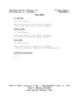
APPENDIX C
BARCODE SAMPLES
APPENDIX D
QUICK SETTINGS
Code 39
C
O
D
1. Quick Settings for Keyboard Wedge Mode
E
3
9
Program
Reset
PC/AT
End
Code 128
C O D
E
1
2
8
2. Quick Settings for RS 232 Mode
Interleaved 2 of 5
Program
Reset
RS-232C
End
1 2 3 4 5 6 7 8 9 0
Coda bar(NW-7)
3. Quick Settings for German Language Keyboard
A $ 9 9 . 9 5 A
German Keyboard
Program
UPC A
End
0
44252 30245
1
EAN-13
4 711234 567899
62
63