1
UHP-8000 DUAL SATELLITE ROUTER
GENERAL DESCRIPTION AND INSTALLATION GUIDE, v3.2
1.4
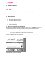
Labeling and sealing
The product is marked with the unique Serial Number on the bottom of the router’s case.
The warranty seals are located on the bottom of the product, at the junction of the two parts of the case.
Product’s warranty will automatically void if such labels have been removed, modified or damaged.
1.5
Packaging and content
Satellite router comes as an integrated chassis. It is recommended to keep original packaging throughout the
entire lifetime. Conservation, storage and transportation of the terminal must be in original packaging.
Standard package includes:
1.
UHP-8000 dual satellite router
2.
Power cables
1.6
Description and principles of operation
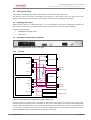
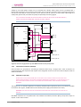
Figure 3: UHP-8000 satellite router – rear view
1.6.1
Overview
UHP-8000
UHP-1000
“A”
Tx
Tx
IF combiner
USB
TAP
TDMA Rx
LAN
LAN “A”
DC
LAN “B”
MCPC Rx
UHP-1000
“B”
IF divider
Rx
Tx
USB
TDMA Rx
USB “A”
USB “B”
LAN
DC
Power supply “A”
Power input “A”
Power supply “B”
Power input “B”
MCPC Rx
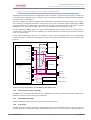
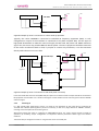
Figure 4 Standard internal configuration of UHP-8000 router
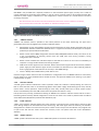
All the interfaces are located on the rear panel of the device. The indicators are located on the front panel.
Indication of each integrated router is located on the front panel of the chassis and similar to the standard display
of UHP- 1000 router. Indications on the left side of the front panel are related to the router "A", the indications on
the right side correspond to the router «B». The LAN and USB interfaces of each router are located on the rear
panel of UHP-8000 chassis and marked with «A» and «B», respectively.
© ROMANTIS 2015
8
www.uhp.net