1
C S - 5 0 0 0 C e n tr a l S ta tio n R e c e iv e r
In s ta lla tio n / O p e r a tio n M a n u a l
AC
POWER
SYSTEM
FAULT
FAULT
OPERATOR
LOGGED IN
ACTIVE
PREV EVENT
CALL PENDING
1
2
PREV
CALL
ACK
LOG
STATUS
LISTEN
3
4
5
6
7
8
9
HOME
HANGUP
LISTEN
*
0
#
NEXT
CALL
ENTER
1
2
3
4
5
6
7
8
9
10
11
MENU
In t e r a c t iv e T e c h n o l o g ie s , In c .
NEXT EVENT
C S 5 0 0 0
12
CS-5000
Central Station Receiver
Installation and User’s
Manual
Interactive Technologies, Inc.
2266 North Second Street
North Saint Paul, MN 55109
1-800-777-1415
For reprints, order manual 86-015
which includes:
466-1337 Rev. C (Manual Text)
466-1558 (Change Pages, if applicable)
466-1336 (Release Notes, if applicable)
Copyright © 1999, ITI
Printed in the USA
Contents
Section 1
System Overview ........................................... 1-1
Features .................................................................. 1-1
Hardware Features .......................................... 1-1
Software Features ........................................... 1-2
Optional Accessories ............................................. 1-2
Formats Compatible with the CS-5000 ................. 1-3
CS-5000 Supported SIA Digital I-III Levels ......... 1-4
Using this Manual .................................................. 1-4
Basic Terms Used in this Manual .......................... 1-5
What’s in the Box .................................................. 1-6
Contacting ITI ....................................................... 1-6
Section 2
Agency Requirements ................................ 2-1
Telephone Requirements ....................................... 2-1
FCC Notice ............................................................ 2-1
UL Requirements ................................................... 2-2
Hardware Requirements ................................. 2-2
Operational Requirements .............................. 2-3
Programming Requirements ........................... 2-3
Section 3
Installation ......................................................... 3-1
Environmental Specifications ................................ 3-1
Electrical Specifications ........................................ 3-1
Overview ............................................................... 3-2
Rack Mounting ...................................................... 3-4
Installing Line Cards ............................................. 3-6
Removing Line Cards ............................................ 3-7
Telephone Line Connection .................................. 3-8
Parallel Printer Connection .................................... 3-8
Printer Cable Pin-Outs ................................... 3-9
Remote Alert Output .................................... 3-10
AC Power Cord Connection ................................ 3-11
Switching to 240 VAC Power ...................... 3-11
How to Verify Earth Ground ........................ 3-13
Battery Connection .............................................. 3-14
Automation Computer Connection ...................... 3-15
Com “Serial Communication” Ports 1 & 2 .. 3-16
Computer Port Baud Rate Selection ............. 3-16
Direct Panel Connection ...................................... 3-16
Section 4
Operation ........................................................... 4-1
Touchpad Function Buttons .................................. 4-1
Displays ................................................................. 4-3
LED Indicators .............................................. 4-3
LCD Status Display ....................................... 4-3
Adjusting LCD Contrast ......................... 4-4
LCD Display Abbreviations ................... 4-5
Initial System Power Up ....................................... 4-5
Logging On and Off .............................................. 4-6
Installer Profile ............................................... 4-6
Operator Profile .............................................. 4-7
Default User Codes ........................................ 4-7
Logging On the System ................................. 4-8
Logging Off the System ................................. 4-8
Modes of Operation ............................................... 4-9
Normal Mode ................................................. 4-9
Manual Operation ................................... 4-9
How to Manually
Acknowledge Calls .......................... 4-9
Automatic Operation ............................... 4-9
Log Only ................................................. 4-9
Program Mode ................................................ 4-9
Main Menu .......................................................... 4-10
Displaying the Main Menu .......................... 4-10
Moving Around in the Main Menu .............. 4-11
Call History .................................................. 4-11
System History ............................................. 4-12
System Info .................................................. 4-12
Set Time & Date .......................................... 4-13
System Restart .............................................. 4-14
Print Menu .................................................... 4-15
Print Report ........................................... 4-16
Printing the Call History ................ 4-16
Printing the System History ........... 4-17
Printing System Configuration ...... 4-17
Printing a Test Page ....................... 4-18
Editing the Event Format ...................... 4-19
Configuring the Printer ......................... 4-20
Program Menu .............................................. 4-20
Diagnostics Menu ........................................ 4-21
Phantom Menu ...................................... 4-21
Message Queue ..................................... 4-22
Event Log .............................................. 4-23
Format ................................................... 4-23
LC Debug Mode ................................... 4-24
LC Statistics .......................................... 4-24
Port Status ............................................. 4-24
Listen-In and Hang Up ........................................ 4-25
Manual (Common) Listen-In Operation ...... 4-25
PBX Listen-In Operation ............................. 4-26
Testing the System .............................................. 4-26
i
Model CS-5000 Central Station Receiver Installation/Operation Manual
Section 5
Programming ................................................... 5-1
Entering Program Mode ........................................ 5-1
Moving Around in Program Mode ................. 5-1
Programming Display Fields .......................... 5-2
Programming Choices ........................................... 5-2
General Options ..................................................... 5-3
Operation Mode .............................................. 5-7
Changing the Operation Mode ................ 5-7
Display Options .............................................. 5-8
Changing the Display Options ................ 5-9
ITI Flags (Set LCD and Printer
Output Options) ....................................... 5-9
Communications ........................................... 5-10
Setting Up the Port Function ................. 5-13
Setting Com Port 1 Parameters ............. 5-14
Setting Com Port 2 Parameters ............. 5-14
Editing the Init String (Com 1, Com 2,
and Parallel Port) ................................... 5-14
To Clear an Init String ................... 5-15
Setting Automation Communication .... 5-16
Setting the Format .......................... 5-16
Enabling or Disabling the
HeartBeat ....................................... 5-16
Time (Period of HeartBeat) ........... 5-16
Ack Time (Acknowledge Time) .... 5-17
ITI Options ..................................... 5-17
Log Recs (For ITI Formats) ........... 5-18
XID (Extended ID for ITI Panels) . 5-18
SupCh (Supervisory Character) ..... 5-18
NoDataCh (No Data Character
for Automation Record) ................. 5-18
Generic (& ITIComp) Revision ..... 5-18
Configuring the On-board
Annunciator Outputs ............................. 5-19
Configuring the Auxiliary
Relay Outputs ........................................ 5-19
System Options ............................................ 5-20
Changing the Backup Battery Setting ... 5-20
Setting the Receiver ID Number ........... 5-21
Setting to Strip or Send Bad Data ......... 5-21
Setting the Auxiliary Relay Contact
Normal State ......................................... 5-21
Message Queue Options ............................... 5-22
Setting the Message Queue
Warning-On Level ................................ 5-22
Setting the Message Queue
Warning-Off Level ................................ 5-22
Set the Maximum Buffer Limit ............. 5-23
Line Card Menu ................................................... 5-23
Adding a Line Card ...................................... 5-27
Edit Line Card .............................................. 5-28
Handshake Sequence ............................. 5-29
ii
Changing the Handshake
Sequence Number .......................... 5-29
Changing the Format Group ......... 5-30
Changing the Handshake
Delay Time .................................... 5-30
Changing the Handshake
Duration Time ................................ 5-30
Changing the Maximum
Handshake Wait Time ................... 5-30
Changing the Acknowledgment
Tone Duration Time ...................... 5-31
Line Options ......................................... 5-31
Setting the Line Card for a Direct
Panel Connection ........................... 5-31
Changing the Number of Rings ..... 5-32
Changing the Ring On Time .......... 5-32
Changing the Ring Off Time ......... 5-32
Changing the Ring Threshold
Voltage ........................................... 5-32
Changing the Phone Line
Sample Rate ................................... 5-33
Listen-In ................................................ 5-33
Changing the Listen Mode ............ 5-33
Changing the PBX String .............. 5-33
Changing the Listen-In Timeout .... 5-34
Editing the Listen-In
Accounts Lists ............................... 5-34
Adding a Listen-In Account .......... 5-35
Editing a Listen-In Account .......... 5-35
Clearing a Listen-In Account ........ 5-35
Trap List ................................................ 5-36
Adding an Account to the Trap List 5-36
Editing an Account in the Trap List 5-36
Clearing an Account from the
Trap List ........................................ 5-36
Miscellaneous Line Options ................. 5-36
Changing the Echo Suppress
Setting ............................................ 5-37
Setting Caller ID ............................ 5-37
Changing the Billing Delay Setting 5-38
Changing the Hunt Group .............. 5-38
ITI Options Menu ......................................... 5-38
ITI SCode (Security Code) Menu ......... 5-38
Adding an Account/SCode ............ 5-39
Editing an Account/SCode ............ 5-39
Clearing (Deleting) an
Account/SCode .............................. 5-39
Adding an SCode to the Table ....... 5-40
Clearing an SCode from the Table 5-40
Date/Time Flag ..................................... 5-40
Changing the Date/Time Flag ........ 5-40
ITI 300 Baud ......................................... 5-40
Changing the ITI 300 Baud Enable 5-41
Audio Mode .......................................... 5-41
Copying Line Cards ..................................... 5-41
Clearing (Deleting) Line Cards .................... 5-42
To Clear or Delete a Line Card
From the Receiver .......................... 5-42
Viewing Line Cards ..................................... 5-42
User List .............................................................. 5-43
Adding a User ............................................... 5-44
Editing a User ............................................... 5-45
Clearing (Deleting) a User ........................... 5-46
Section 6
Compatible Reporting Formats ............ 6-1
Formats By Communication Group ...................... 6-1
Format Numbers Used In Printer Output .............. 6-3
Section 7
Troubleshooting ............................................ 7-1
Error Messages ...................................................... 7-1
Troubleshooting Process ....................................... 7-5
Removing the Power Supply/Mother
Board Assembly ............................................. 7-5
Replacing the Mother Board/Power
Supply Assembly ............................................ 7-6
Safe Mode .............................................................. 7-6
Updating the Receiver Software ............................ 7-6
Section 8
Automation
Communication Formats .......................... 8-1
Introduction ........................................................... 8-1
Section Terms and Conventions ..................... 8-1
SIA-CIS (Computer Interface Standard) Format . 8-2
Data String Description And
Special Characters .......................................... 8-3
Basic Message Format ................................... 8-4
Modifier Codes ............................................... 8-6
Long Calls ...................................................... 8-6
System Status Messages ................................. 8-8
HeartBeat ........................................................ 8-9
Communication from a
Computer to the CS-5000 ............................... 8-9
ACKing and NACKing Data .................. 8-9
Link Test ............................................... 8-10
SIA-2000 Format ................................................ 8-11
ITI Generic Computer Format ............................. 8-11
Convention Used In This Subsection ........... 8-11
Report Record .............................................. 8-11
Control Panel Type and Zone
Attribution Byte .................................... 8-12
Extended Panel ID Codes ..................... 8-13
Alarm Codes ......................................... 8-14
Log Record ................................................... 8-15
Test Record .................................................. 8-16
Okay Record ................................................ 8-16
ACKing and NACKing Data ....................... 8-17
ITI Comp (Computer Interface) Format .............. 8-17
Convention Used In This Subsection ........... 8-17
General Record Structure ............................. 8-18
Report Record .............................................. 8-19
Information Field Identifiers ................. 8-20
Panel Type Characters .......................... 8-21
Condition Codes ................................... 8-22
Test Record .................................................. 8-23
Supervisory Record ...................................... 8-24
Log Records ................................................. 8-25
Checksum/Control Field .............................. 8-25
ITI METERMINDER Format ............................. 8-26
Meter Format ................................................ 8-26
Output Record Format ................................. 8-28
Meter Test Record ........................................ 8-29
Commands Initiated by the
Automation Computer ......................................... 8-29
Remote Log-on/Log-off ............................... 8-30
Force Hang-up Request ................................ 8-31
Add or Delete a Listen-in Account .............. 8-31
Common Listen-in Extend/End Request ...... 8-33
PBX Listen-in String .................................... 8-34
Add or Delete a Trap Account ..................... 8-34
Glossary
Appendix A
Programming Quick Chart
Appendix B
US ASCII Character Code
iii
Model CS-5000 Central Station Receiver Installation/Operation Manual
Appendix C
CS-5000 Central Station
Receiver Menu Map
Appendix D
CS-5000 Specifications
Appendix E
Automation Output Version Control
Index
iv
List of Tables
Table 1-1:
Table 1-2:
Table 1-3:
Optional Accessories for the CS-5000 Receiver .........................1-2
Formats Compatible with the CS-5000 .......................................1-3
CS-5000 and SIA Levels I-III Comparison .................................1-4
Table 3-1:
External Printer Cable Pin Description .......................................3-9
Table 4-1:
Table 4-2:
Table 4-3:
Table 4-4:
Table 4-5:
Table 4-6:
Table 4-7:
Table 4-8:
Table 4-9:
Touchpad Buttons Description ....................................................4-2
LED Description ..........................................................................4-3
LCD and Printer Abbreviations ...................................................4-5
Main Menu Option Items by Profile ...........................................4-7
Default User Codes ......................................................................4-7
Main Menu Controls ..................................................................4-11
Printer Menu Choices ................................................................4-15
Event Format Choices and Meaning .........................................4-19
Phantom Signals Formats List ...................................................4-21
Table 5-1:
Table 5-2:
Table 5-3:
Table 5-4:
Table 5-5:
Table 5-6:
Table 5-7:
Table 5-8:
Table 5-9:
Table 5-10:
Table 5-11:
Table 5-12:
Table 5-13:
Table 5-14:
Table 5-15:
Table 5-16:
Main Menu Controls ....................................................................5-1
Types of Programming Fields .....................................................5-2
General Options Items and Description .....................................5-3
Operation Mode Choices and Descriptions .................................5-7
Display Options and Descriptions ..............................................5-8
Communications Options and Descriptions .............................5-10
Initialization String Characters ..................................................5-15
ITI Automation Format Options ................................................5-17
On-board Annunciator and Auxiliary Relay Options ................5-19
System Options .........................................................................5-20
Line Card Menu Options ..........................................................5-24
Edit Line Card List Items and Description ...............................5-28
Valid Programmable String Characters ....................................5-34
Account Characters ...................................................................5-35
User List Menu Items and Steps ................................................5-43
Available Characters .................................................................5-44
Table 6-1:
Table 6-2:
CS-5000 Compatible Formats ....................................................6-1
Formats By Report Number .......................................................6-3
Table 7-1:
Error Messages ...........................................................................7-1
Table 8-1:
Table 8-2:
Table 8-3:
Table 8-4:
Table 8-5:
Table 8-6:
Table 8-7:
Table 8-8:
Data String Description ...............................................................8-3
Special Characters .......................................................................8-4
Modifier Codes Used With The CS-5000 ...................................8-6
System Status Messages ..............................................................8-8
Number and ITI Digit Equivalent ..............................................8-11
Report Record Components ......................................................8-12
Upper Nibble Description ..........................................................8-12
Non-ITI Formats Lower Nibble Description .............................8-13
v
Model CS-5000 Central Station Receiver Installation/Operation Manual
Table 8-9:
Table 8-10:
Table 8-11:
Table 8-12:
Table 8-13:
Table 8-14:
Table 8-15:
Table 8-16:
Table 8-17:
Table 8-18:
Table 8-19:
Table 8-20:
Table 8-21:
Table 8-22:
Table 8-23:
Table 8-24:
Table 8-25:
Table 8-26:
Table 8-27:
Table 8-28:
Table 8-29:
Table 8-30:
Table 8-31:
Table 8-32:
Table 8-33:
Table 8-34:
Table 8-35:
Table 8-36:
Table 8-37:
Table 8-38:
Pulse Formats Lower Nibble Description .................................8-13
Extended Panel ID Codes (XID) ..............................................8-13
Alarm Codes and Descriptions .................................................8-14
Log Record Components and Description ................................8-16
Test Record Components and Description ................................8-16
Okay Record Components and Description .............................8-17
Number and ITI Digit Equivalent ..............................................8-17
Type of Record Identifiers .........................................................8-18
Record Components ..................................................................8-18
Report Record Components and Description ...........................8-19
Information Field Identifiers ....................................................8-20
Panel Type Characters ..............................................................8-21
Condition Codes and Descriptions ...........................................8-22
Test Record Information Fields and Descriptions .....................8-24
Supervisory Record Information Fields And Descriptions .......8-24
Log Record Information Fields And Descriptions ....................8-25
Checksum Verification Process .................................................8-26
METERMINDER (COM 2) Reports ........................................8-27
Response Messages by the CS-5000 Receiver ..........................8-29
Command Requests by Identifiers ............................................8-30
Log-in Request Components ....................................................8-30
Log-off Request Components ....................................................8-31
Force Hang-Up Request Components .......................................8-31
Add Listen-in Account Request Components ...........................8-32
Delete a Listen-in Account Request Components .....................8-32
Extend Listen-in Period Request Components ..........................8-33
End Listen-in Period Request Components ...............................8-33
Create PBX Listen-in String Request Components ...................8-34
Add Trap Account Request Components .................................8-34
Delete Trap Account Request Components ..............................8-35
Table A-1: Programming Quick Chart ....................................... Appendix A-1
Table B-1: US ASCII Character Codes ...................................... Appendix B-1
Table E-1:
Table E-2:
Table E-3:
Table E-4:
vi
New Event Codes ...................................................... Appendix E-1
Panel ID Characters ................................................... Appendix E-2
SIA-DCS Format ...................................................... Appendix E-4
ITI Contact ID Table .............................................. Appendix E-14
Section 1
System Overview
This manual describes installation, operation, and programming of the Model CS-5000
Central Station Receiver.
This section lists features, optional accessories, compatible formats, and SIA options
supported. This section also contains conventions held throughout the manual, terminology
relevant to this product, and other information.
Note
Although the CS-5000 can be used as a desk-top receiver,
it must be rack-mounted for UL-listed installations.
Features
Hardware Features
• Supports both 120 and 240 VAC, 60 Hz installations
• External annunciation with auxiliary Form C dry contact relay (programmable)
• On-board PZT alert (programmable)
• 1 parallel port
• 2 serial ports
• 2 SBUS future expansion connectors
• Modular configuration for easy replacement and repair
• 4 line, back-lit LCD Display with 20 characters for each line
• On-board touchpad for manual operation and programming
• LEDs to indicate system operations
• Rack mountable design
• One line card will communicate with all supported formats
• Supports up to 12 line cards which operate independent of each other
• Line card parameters are stored on the MCPU for faster removal and replacement
• Line cards support Caller ID and Caller Name Delivery
• Line cards are individually programmable for format priority and ring parameters
• Line cards support direct connect phone line monitoring
1-1
Model CS-5000 Central Station Receiver Installation/Operation Manual
Software Features
• Programmable display options for time and date information
• View or print the history information by priority, call, or event
• Two user profiles to control user access to the receiver
• Supports up to 40 users
• Listen-in and trap accounts support wild card variables. Up to 20 accounts available per
line card (20 for listen-in and 20 for trap accounts)
• Listen-in selectable for direct, hook flash, or PBX phone system
• Programmable port configuration for automation, printer, and backup support
• 500 event history buffer
Optional Accessories
Unless otherwise indicated, the following accessories for the Model CS-5000 receiver are
available from the ITI Order Processing Department. You can contact ITI Order Processing
by phone or by mail. The toll free number is 1-800-777-4841. Our mailing address is 2266
North Second Street, North Saint Paul, MN 55109.
Table 1-1: Optional Accessories for the CS-5000 Receiver
Item
ITI Model Number
(if applicable)
Line card
ITI 13-417
The line card monitors the phone line, detects ring and processes
the message from the communicating panel.
Backup battery
ITI 60-680
A 12VDC 7ah battery which will provide a minimum 4 hours of
backup power during an AC power loss. (See Agency
Requirements section for UL backup power requirements. See
Installation section for installation instructions.)
Printer cable
Not available from ITI
A standard 25-pin cable used to connect the CS-5000 receiver to
an external parallel printer.
Rack-mounting
cabinet
Not available from ITI
Used to rack mount the CS-5000 receiver as required by UL. (See
Agency Requirements section for specifications and vendor
information.)
Blank filler panels
Not available from ITI
Used to fill up any unused cabinet spaces as required by UL.
Parallel printer
Not available from ITI
ITI Model CS-5000 receiver requires the parallel printer to
generate report history hardcopy.
(Okidata Microline
320 Turbo, 9-pin)
1-2
Description/Comments
System Overview
Formats Compatible with the CS-5000
Table 1-2 shows the formats that the CS-5000 receiver can decode and the handshake
frequency groups which accommodate that format (see “Line Card Menu” in Section 5 for
line card programming). Each line card can decode every format listed below. Setting the
handshake order only prioritizes the type of communication done by each line card. Section 6
of this manual describes the formats in greater detail.
Table 1-2: Formats Compatible with the CS-5000
Format Name
Handshake
BFSK
1400 or 2300 Hz
4+2
1400 Hz
3+1/3+1 Extended
1400 or 2300 Hz
Sescoa 3+1/Franklin 3+1
2300 Hz
Radionics 3+1 Checksum
1400 or 2300 Hz
4+1 Extended
1400 or 2300 Hz
SX-III, SX-IVA
2225 Hz
SX-IVB
2225 Hz
ITI SX-V
2225 Hz
ITI SX-V Special
2225 Hz
ITI Commander
2225 Hz
ITI RF Commander, Harbor Gard
2225 Hz
ITI Commander 2000, LifeGard
2225 Hz
ITI CareTaker+, SecurityPro 4000,
MeterMinder
2225 Hz
ITI UltraGard
2225 Hz
ITI SIMON
2225 Hz
ITI FONSAFE, PhoneWatch
2225 Hz
SIA DCS
2225 Hz
SIA 2000 (pending approval)
2225 Hz
Ademco Contact ID
1400 and 2300 Hz
Ademco Super Fast
1400 and 2300 Hz
Acron Touch Tone
1400 and 2300 Hz
Ademco Express
1400 and 2300 Hz
DTMF 4+2
1400 and 2300 Hz
1-3
Model CS-5000 Central Station Receiver Installation/Operation Manual
CS-5000 Supported SIA Digital I-III Levels
Table 1-3 compares the CS-5000 receiver to SIA Digital Compatibility Levels I, II, and III
and indicates compliance.
Table 1-3: CS-5000 and SIA Levels I-III Comparison
Level III
Level II
Level I
CS5000
Function/Capability
Transmitter
Receiver
✔
Support Tonal Acknowledgments
required
required
✔
Support N Blocks with Zone Numbers Only
required
required
✔
Support Single Account Block per Call
required
required
✔
Support O Blocks
(optional)
required
✔
Support X Blocks
(optional)
required
✔
Support 300 Baud (Fast)
(optional)
required
Support Configuration Block
required
required
Support Data Acknowledgments
required
required
✔
Support Modifier Codes id, da and ti.
(optional)
required
✔
Support Multiple Account Blocks per Call
(optional)
required
✔
Support E Blocks
(optional)
required
✔
Support Data Codes with Units Numbers
(optional)
required
Support RECEIVER Call Out and Access Passcode
required
required
Support Reverse Channel C Blocks
required
required
Support Reverse Channel P Blocks
required
(optional)
Support Reverse Channel A Blocks
(optional)
required
Support Dynamic Block and Group Sizes
(optional)
required
✔
Support Listen-in
(optional)
required
✔
Support A Blocks to RECEIVER
(optional)
required
Support V-Channel communication
(optional)
(optional)
Using this Manual
This manual contains information on how to install, program, and operate the CS-5000
receiver. ITI strongly suggests you review this manual in its entirety to become familiar with
product procedures and parameters. Once you are familiar with the product, you can use this
manual as a reference document.
This manual uses the following conventions:
•
•
•
•
1-4
5, ENTER, ▲, ▼
These bold typefaces and symbols represent touchpad buttons.
LCD display
This typeface represents LCD display messages.
Manual pages are numbered by section. For example, “5-1” is page 1 of section 5.
When this manual refers to default settings, it means programmable options set at the factory. Any programming after the receiver is powered up will change these settings.
System Overview
Basic Terms Used in this Manual
This section lists some basic terms specific to this product and their meaning. (Refer to the
Glossary for a complete list of terms.)
Term
Meaning
Communication Group
ITI has separated the different types of communication by handshake type. These handshake types
can be assigned in a numbered order (see “Formats Compatible with the CS-5000” in Section 1).
Listen-in
Listen-in is the ability to listen in to what is happening in real-time from the central station to a
remote location. This can help the central station operator determine if he or she should dispatch
for a particular alarm situation.
PZT
PZT is an abbreviation for a piezo alert sounder.
PIN
An abbreviation for Personal Identification Number. PINs are used to log in and out of the
receiver.
SBUS
Serial Bus interface for future expansion.
MCPU
Master Central Processing Unit.
Main Menu
The main menu will be displayed as either <Installer Menu> or <Operator Menu> . However,
this manual will refer to them as the main menu.
ACK
Stands for acknowledgment.
NACK
Stands for no acknowledgment.
1-5
Model CS-5000 Central Station Receiver Installation/Operation Manual
What’s in the Box
This section contains a list of the parts that are shipped with the CS-5000 receiver and a brief
description of their intended use.
Item
Quantity
Battery/alert relay wiring harness
Description
1
Wiring harness used to connect the CS-5000 receiver to a backup
battery. It also provides a normally open or normally closed output
for an alert sounder.
CS-5000 Installation/Operation
Manual
1
A manual covering installation and operation information related to
the CS-5000 receiver.
Central station receiver
1
The central station receiver assembly.
Line card
1
Line card for phone lines.
1
Tie wrap used as a strain relief on the phone cord. See Figure 3-3 for
location of strain relief tabs.
4
#10-32 x 3/8 flat head screws used to mount the receiver to a UL
listed rack. (See Section 3, “Installation,” for rack mounting
instructions.)
1
A 7 foot long telephone cable with RJ-11 connectors.
1
AC power cable used to connect the CS-5000 receiver to an AC wall
plug.
Strain relief tie wrap
Receiver mounting screws
Telephone cord
Power cable
Contacting ITI
If you have a question or encounter a problem not covered in this manual, contact ITI
Technical Support by telephone at 1-800-777-2624. To order parts, contact ITI Order
Processing at 1-800-777-4841 or fax in your question to 1-800-777-4842.
1-6
Section 2
Agency Requirements
Telephone Requirements
If requested by the telephone company, the following information must be provided before
connecting this device to the phone lines:
A.
Manufacturer:
Interactive Technologies, Inc. (ITI)
B.
Model Number:
CS-5000
C.
FCC Registration Number:
AC6USA-31519-AL-E
D.
Type of jack (to be installed by the
telephone company):
RJ31X
E.
Ringer Equivalence Number (REN):
0.1B
This device may not be connected directly to coin telephones or party line services.
This device cannot be adjusted or repaired in the field. In case of trouble with the device,
notify the installing company or ITI for an RMA and then return it to:
Interactive Technologies, Inc.
2266 North Second Street
North Saint Paul, MN 55109
Telephone: 1-800-777-2624
The telephone company may make changes in its facilities, equipment, or procedures that
could affect the operation of the equipment. If this happens, the telephone company will
provide advance notice to allow you to make the necessary modifications to maintain
uninterrupted service.
FCC Notice
This device complies with FCC Rules Part 68.
This device has been verified to comply with FCC Rules Part 15. Operation is subject to the
two following conditions: (1) This device may not cause radio interference, and (2) This
device must accept any interference received including interference that may cause undesired
operation.
2-1
Model CS-5000 Central Station Receiver Installation/Operation Manual
UL Requirements
Follow the procedures outlined in the sections below for listing as an NFPA 72 Central Station
Service installation. The CS-5000 is also suitable for household and commercial burglary
service. Note that installation regulations are subject to the jurisdiction of a local authority.
Hardware Requirements
See Figure 3-4 and Figure 3-5 for diagrams of a suggested installation.
1. A second CS-5000 must be installed as a back-up in case the primary CS-5000 fails. The
back-up system must be able to take over within 30 seconds.
(Note: This requirement does not apply to burglary-only installations.)
2. The CS-5000 must be housed in a UL listed for fire protective signaling use, metal rackmounting cabinet. A recommended enclosure is a listed control unit accessories system
cabinet manufactured by Atlas/Soundelier. (The WA200 series, intended for 19-inch rack
mount panels, can be used.) A taller cabinet could be used to house additional units.
3. Back-up battery does not provide standby time required for UL and NFPA standards. A
UPS (uninterruptable power supply), listed for Fire Protection Signaling Use, must be
utilized when standby power is required.
4. Any unused front panel rack space must be filled with blank panels so that all wiring
remains enclosed.
5. The external conduit must exit through the knockouts in the cabinet or go directly through
the floor.
2-2
Agency Requirements
Operational Requirements
1. The transmitters reporting to the CS-5000 must be UL Listed DACTs (digital alarm communicator transmitters).
2. The central station must provide a minimum of 24 hours of back-up power within 30
seconds of an AC power loss. The back-up must either be in the form of a UL listed UPS
or electrical generator.
3. If the CS-5000 is not automated, the central station operator must check for the 24 hour
test signals from the communicators.
(Note: This requirement does not apply to burglary-only installations.)
4. The connection between the CS-5000 and the UL listed computer should be according to
the pin configuration for Com port 1 as shown in the Installation section of this manual.
5. If a computer is used, the computer and its accessories must be installed in the same room
as the receiver.
6. If the listen-in feature is used the receiver must meet the loading requirements specified in
NFPA 72 paragraph A-4-5.3.2.2.2.3. Additional line cards can be installed to meet this
requirement; however, the additional line cards can not be programmed for listen-in.
Programming Requirements
In a UL listed installation, the Model CS-5000 receiver must be programmed according to the
following procedure:
•
•
Do NOT use the alarm output relay in UL installations.
Each log-on code must have at least four digits.
2-3
Model CS-5000 Central Station Receiver Installation/Operation Manual
2-4
Section 3
Installation
This section contains information necessary to install a CS-5000 Central Station Receiver.
Important!
Do not connect power to the system until you
have read these instructions carefully.
Environmental Specifications
•
•
•
•
Operating temperature range is 32° to 120° F.
Indoor use only.
Maximum 85 percent non-condensing relative humidity.
Non-corrosive environment.
For detailed specifications, see Appendix D.
Electrical Specifications
Line voltage
Fuse
Back-up battery connection
(Back-up battery does not provide standby time required for
UL and NFPA standards. A UPS (uninterruptable power
supply), listed for Fire Protection Signaling Use, must be
utilized when standby power is required.
Auxiliary relay contacts
120VAC ± 10%
60Hz, 100VA
240VAC ± 10%
60Hz, 100VA
3A Slow Blow
Input
10.2 to 14.0 VDC
3 Amp Max.
Output
13.65 VDC
1 Amp charging current
2.5 Amp @ 48VDC
Resistive Power Limited
2.5 Amp @ 48VAC
Resistive Power Limited
3-1
Model CS-5000 Central Station Receiver Installation/Operation Manual
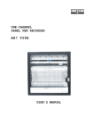
Overview
The CS-5000 is assembled at the factory. One line card is shipped with the CS-5000 receiver.
Follow the procedures described in “Installing Line Cards” in Section 3 to install additional
line cards.
AC
POWER
SYSTEM
FAULT
FAULT
OPERATOR
LOGGED IN
ACTIVE
PREV EVENT
CALL PENDING
1
2
LISTEN
3
PREV
CALL
ACK
4
LOG
STATUS
5
6
7
8
9
HOME
HANGUP
LISTEN
*
1
2
3
4
5
6
7
8
9
10
11
12
MENU
NEXT EVENT
#
0
NEXT
CALL
ENTER
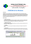
Face Plate Screws
Figure 3-1 Model CS-5000 Front View
AC
POWER
SYSTEM
FAULT
OPERATOR
LOGGED IN
PREV EVENT
CALL PENDING
1
2
3
4
5
6
PREV
CALL
ACK
LOG
STATUS
MENU
P2
7
8
9
HOME
HANGUP
LISTEN
*
0
NEXT
CALL
ENTER
#
P3
P4
P5
NEXT EVENT
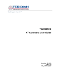
Main Power Switch
Inserted Line Card
Phone Line Connector
Phone Line Slots
Figure 3-2 Model CS-5000 Front View (Front Plate Removed)
3-2
Line Card Guides
Installation
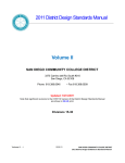
AC Power
Cord Connector
This device complies with FCC Rules Part 68.
This device has been verified to comply with FCC Rules Part 15.
Operation is subject to the following two conditions: (1) This
device may not cause radio interference, and (2) This device must
accept any interference received including interference that may
cause undesired operation.
FCC Registration No. AC6USA-31519-AL-E
R.E.N. 0.1B
Fuse
100 VA
FUSE
1.5A SLOW
BLOW
EXTERNAL
BATTERY
AC
120 VAC ± 10%
240 VAC ± 10%
50-60 Hz
B
REPLACE ONLY
WITH A FUSE
OF SAME TYPE
AND RATING
UNUSED
N.O.
B+
N.C.
Remote Relay/
Battery Connector
WARNING!
HIGH VAOLTAGE PRESENT
DISCONNECT AC LINE AND
ALL OTHER CONNECTORS
PROIR TO SERVICING
C
COM 1
REMOTE ANNUNCIATOR RELAY
RATING: 2.5A, 48VAC/DC
Silent Knight Security Systems
Model: 9800
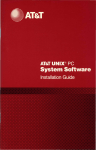
Phone Line Slots
SBUS
Phone Line
SBUS Connectors
Strain Relief
Tie Wrap Holders
COM 2
PARALLEL PORT
Serial Ports
Parallel
Printer Port
Figure 3-3 Model CS-5000 Rear View
3-3
Model CS-5000 Central Station Receiver Installation/Operation Manual
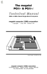
Rack Mounting
This diagram shows how to mount the model CS-5000 in a UL-listed rack enclosure.
AC
POWER
SYSTEM
FAULT
FAULT
OPERATOR
LOGGED IN
ACTIVE
PREV EVENT
CALL PENDING
1
2
LISTEN
3
PREV
CALL
ACK
4
LOG
STATUS
5
Receiver
Mounting
Screws
(Flat Head
supplied
with receiver)
6
7
8
9
HANGUP
LISTEN
2
3
4
5
6
7
8
9
10
11
12
Model
CS-5000
Receiver
NEXT EVENT
#
0
1
MENU
HOME
*
NEXT
CALL
ENTER
AC
POWER
SYSTEM
FAULT
OPERATOR
LOGGED IN
PREV EVENT
CALL PENDING
1
2
3
PREV
CALL
ACK
LOG
STATUS
4
5
6
7
8
9
HOME
HANGUP
LISTEN
*
0
#
NEXT
CALL
ENTER
MENU
P2
P3
P4
P5
NEXT EVENT
Back-up
Model CS-5000
Receiver
(Shown With
Face Plate
Removed)
Blank
(Filler)
Panels
Figure 3-4 Rack Mount Enclosure (Front View)
Note: All wiring that exits cabinet must be in a electrical conduit.
3-4
Installation
Power/non-power limited and
high/low voltage wiring lines must
be separated by 1/4" spacing
Model
CS-5000
Receiver
This device complies with FCC Rules Part 68.
This device has been verified to comply with FCC Rules Part 15.
Operation is subject to the following two conditions: (1) This
device may not cause radio interference, and (2) This device must
accept any interference received including interference that may
cause undesired operation.
FCC Registration No. AC6USA-31519-AL-E
100 VA
FUSE
1.5A SLOW
BLOW
EXTERNAL
BATTERY
AC
120 VAC ± 10%
240 VAC ± 10%
50-60 Hz
R.E.N. 0.1B
REPLACE ONLY
WITH A FUSE
OF SAME TYPE
AND RATING
B
N.C.
WARNING!
HIGH VAOLTAGE PRESENT
DISCONNECT AC LINE AND
ALL OTHER CONNECTORS
PROIR TO SERVICING
UNUSED
N.O.
B+
C
COM 1
REMOTE ANNUNCIATOR RELAY
RATING: 2.5A, 48VAC/DC
SBUS
Silent Knight Security Systems
Model: 9800
PARALLEL PORT
COM 2
This device complies with FCC Rules Part 68.
This device has been verified to comply with FCC Rules Part 15.
Operation is subject to the following two conditions: (1) This
device may not cause radio interference, and (2) This device must
accept any interference received including interference that may
cause undesired operation.
FCC Registration No. AC6USA-31519-AL-E
EXTERNAL
BATTERY
AC
120 VAC ± 10%
240 VAC ± 10%
50-60 Hz
R.E.N. 0.1B
100 VA
FUSE
1.5A SLOW
BLOW
REPLACE ONLY
WITH A FUSE
OF SAME TYPE
AND RATING
B
UNUSED
N.O.
B+
N.C.
WARNING!
HIGH VAOLTAGE PRESENT
DISCONNECT AC LINE AND
ALL OTHER CONNECTORS
PROIR TO SERVICING
C
COM 1
REMOTE ANNUNCIATOR RELAY
RATING: 2.5A, 48VAC/DC
Silent Knight Security Systems
Model: 9800
SBUS
COM 2
PARALLEL PORT
Low voltage
power limited
Tie-wrap groups
of wires to the
enclosure
Shelf or support
bracket (under
each unit)
Incoming
Telephone
Lines
Power limited
wires for SBUS
and Com ports.
Tie wrap wire
to the enclosure.
Listed receptable
(rated 15A 125VAC)
Incoming line
power 120VAC, 60Hz
Rear Cabinet Door
(not shown)
Figure 3-5 Rack Mount Enclosure (Rear View)
Note: All wiring that exits cabinet must be in a electrical conduit.
3-5
Model CS-5000 Central Station Receiver Installation/Operation Manual
Installing Line Cards
Caution
To reduce the risk of electrical shock and/or damage
to the receiver, follow these steps in order.
1. Open the CS-5000's front panel by unscrewing the four front plate retaining screws
located on the front of the panel (Figure 3-1).
2. Turn off the CS-5000’s AC power switch (Figure 3-2).
3. When the front panel is removed, you can see that there are 12 slots for line cards. The
receiver recognizes each slot by number 1 through 12 (slot one is closest to the keypad and
display). It is not necessary to put line cards in numbered order because the receiver continually polls each slot to see if existing line cards are functioning and if it is still in its
slot. The receiver also looks to see if a new line card has been added. Figure 3-6 shows
line card placement.
Phone Line Connector
Line Card Guides
PREV EVENT
PREV
CALL
NEXT
CALL
ENTER
MENU
P2
P3
P4
P5
NEXT EVENT
Phone Line Slots
Figure 3-6 Line Card Locations
4. Position the line card as shown in Figure 3-7.
Top of Line Card
Insert from
front in this
direction
Line Card
Display
LEDs
Model 9810
Phone Line Connector
Figure 3-7 Line Card Position and Components
3-6
Installation
5. Carefully slide the card into its guides (both top and bottom) until it fits into its connector
at the back of the receiver. Gently push the card completely into the connector. The card
is now in place.
6. Connect telephone line. (See “Telephone Line Connection” in Section 3.)
Note: Use the tie wrap (provided with each line card) on the tie wrap holder to add strain relief to the telephone
lines. (See Figure 3-3.)
7. Power up the CS-5000.
8. Close the CS-5000's front panel and tighten the front plate retaining screws to hold the
front plate in place. If you are simply replacing a line card with another card of the same
type and are using the same format settings, your installation is now complete. If not continue to the next step.
9. Enter programming mode to select the appropriate handshake configuration. (See “Entering Program Mode” in Section 5 for programming procedures.)
Removing Line Cards
If you need to remove a line card:
1. Open the CS-5000's front panel by unscrewing the four front plate retaining screws
located on the front of the panel (Figure 3-1).
2. Turn off the CS-5000’s AC power switch (Figure 3-2).
3. With the front panel removed, you can see that there are 12 slots for line cards.
4. Locate the line card to be removed.
5. Unplug the telephone line (Figure 3-6, Figure 3-7).
6. From the front side of the receiver pull the line card straight forward. This will pull the
card free from the connector.
7. When the card is free, slide it carefully out of the receiver.
Note: If replacing a line card with a new one, see “Installing Line Cards” in Section 3.
8. Power up the CS-5000.
9. Close the CS-5000's front panel and tighten the front plate retaining screws to hold the
front plate in place.
10. Enter programming mode to clear the line card from the system. (See “Entering Program
Mode” in Section 5 for programming procedures.)
3-7
Model CS-5000 Central Station Receiver Installation/Operation Manual
Telephone Line Connection
See Figure 3-6 for the location of the phone line inputs. Connections to the CS-5000 phone
jacks are made with a standard 7-foot phone cord (provided with each line card).
Use the following procedure to connect phone lines to the line cards:
1. Remove the front panel of the CS-5000 receiver by loosening the front plate retaining
screws (Figure 3-1).
2. From the back side of the receiver insert the telephone line through the corresponding slot
for the desired line card (Figure 3-6, Figure 3-7).
3. Gently push it all the way through to the front side of the receiver.
4. Plug the RJ-11 phone connector into the connector on the line card (Figure 3-6, Figure 37).
Note: Use the tie wrap (provided with each line card) on the tie wrap holder to add strain relief to the telephone
lines (Figure 3-3.)
5. Replace the front panel of the CS-5000 receiver by tightening the front plate retaining
screws (Figure 3-1).
Parallel Printer Connection
The CS-5000 Receiver connects to a parallel printer for UL applications. To connect the
printer to the CS-5000 receiver follow these steps:
1. Connect the standard parallel printer cable to the parallel printer port on the back of the
CS-5000 receiver (Figure 3-8).
2. Connect the other end to the printer’s parallel printer port connector.
Note: Make sure that printer power is turned off.
3. Turn on printer power.
3-8
Installation
This device complies with FCC Rules Part 68.
This device has been verified to comply with FCC Rules Part 15.
Operation is subject to the following two conditions: (1) This
device may not cause radio interference, and (2) This device must
accept any interference received including interference that may
cause undesired operation.
FCC Registration No. AC6USA-31519-AL-E
100 VA
FUSE
1.5A SLOW
BLOW
EXTERNAL
BATTERY
AC
120 VAC ± 10%
240 VAC ± 10%
50-60 Hz
R.E.N. 0.1B
B
B+
N.C.
REPLACE ONLY
WITH A FUSE
OF SAME TYPE
AND RATING
WARNING!
HIGH VAOLTAGE PRESENT
DISCONNECT AC LINE AND
ALL OTHER CONNECTORS
PROIR TO SERVICING
UNUSED
N.O.
C
COM 1
REMOTE ANNUNCIATOR RELAY
RATING: 2.5A, 48VAC/DC
SBUS
Silent Knight Security Systems
Model: 9800
COM 2
PARALLEL PORT
To Printer
Figure 3-8 Parallel Printer Cable Connection to CS-5000
Printer Cable Pin-Outs
25 pin (Centronics type) printer cables are a standard items at most electronic stores.
However, if you create your own cable, use the pin description in Table 3-1.
Table 3-1: External Printer Cable Pin Description
CS-5000
Pin #
Signal
Direction
Description
1
Data Strobe (Low)
Out
A low strobe pulse to read data in the pulse width is greater than 0.5
microseconds.
2
Data Bit 1
Out
3
Data Bit 2
Out
These signals represent information of the first to eighth bits of parallel
data. Each signal is at high level when the data is logic 1 and low when
it is logic 0.
4
Data Bit 3
Out
5
Data Bit 4
Out
6
Data Bit 5
Out
7
Data Bit 6
Out
8
Data Bit 7
Out
9
Data Bit 8
Out
10
AckNlg
In
A low pulse from the printer signals the control that the printer is ready
for additional data.
11
Busy
In
A high level indicates that the printer is busy.
3-9
Model CS-5000 Central Station Receiver Installation/Operation Manual
Table 3-1: External Printer Cable Pin Description
12
Paper Empty
In
A high level indicates that the printer is out of paper.
13
Select
In
A low level indicates the printer is off-line or in an error condition.
14
Not used
-
-
15
Not used
-
-
16
Logic ground
-
Logic ground for printer
17
Not used
-
-
Logic Ground
-
Ground return for data lines.
18 to 25
Figure 3-9 shows the connector pin numbering.
10.0'
Printer
Receiver
Pin 1
Pin 13
Pin 14
Pin 25
Figure 3-9 Parallel Printer Port Connector Pins
Remote Alert Output
1. Plug the battery/relay wiring harness onto the connector on the back of the CS-5000
receiver (Figure 3-10).
Note: The remote alert output is a “form C” relay with normally open or normally closed contacts.
2. Connect the white wire to circuit common.
3. Use the yellow wire for a normally closed circuit, or
Use the brown wire for a normally open circuit.
3-10
Installation
COM 1
SBUS
COM 2
PARALLEL PORT
Power limited
Non-power Limited
Black: Battery Negative
Red: Battery Positive
Note:
A 1/4 inch spacing must be
maintained between the battery
wires and the relay wires. If this
spacing cannot be maintained, use
non-power limited wiring methods
as described in NFPA 70 National
Electrical Code.
The relay can only be used with
a listed power limited resistive
load, class 2 or class 3 supply.
White: Relay Common
Yellow: Relay N.C.
Brown: Relay N.O.
Figure 3-10 CS-5000 Remote Alert Output/Backup Battery Connection
AC Power Cord Connection
1. Before the AC power cord is connected, make sure that the power switch is off (down).
2. Connect the power cord into the receptacle on the back of the CS-5000.
3. Plug the power cord into a 120 VAC 60 Hz outlet (three-prong type only). The outlet
should be unswitched, so that power remains on 24 hours a day. The outlet must also be
earth grounded. See “How to Verify Earth Ground” in Section 3 if you need to measure
for proper earth grounding.
Switching to 240 VAC Power
1.
2.
3.
4.
5.
Remove the front plate by unscrewing the front plate retaining screws (Figure 3-1).
Turn the main power switch off (Figure 3-12).
Disconnect AC power cable.
Disconnect the back-up battery (Figure 3-14).
On the back of the receiver remove the four screws that hold the mother board/power supply assembly to the chassis (Figure 3-11).
3-11
Model CS-5000 Central Station Receiver Installation/Operation Manual
This device complies with FCC Rules Part 68.
This device has been verified to comply with FCC Rules Part 15.
Operation is subject to the following two conditions: (1) This
device may not cause radio interference, and (2) This device must
accept any interference received including interference that may
cause undesired operation.
FCC Registration No. AC6USA-31519-AL-E
100 VA
FUSE
REPLACE ONLY
WITH A FUSE
OF SAME TYPE
AND RATING
1.5A SLOW
BLOW
EXTERNAL
BATTERY
AC
120 VAC ± 10%
240 VAC ± 10%
50-60 Hz
R.E.N. 0.1B
B
WARNING!
HIGH VAOLTAGE PRESENT
DISCONNECT AC LINE AND
ALL OTHER CONNECTORS
PROIR TO SERVICING
UNUSED
N.O.
B+
C
N.C.
COM 1
REMOTE ANNUNCIATOR RELAY
RATING: 2.5A, 48VAC/DC
Silent Knight Security Systems
Model: 9800
SBUS
COM 2
PARALLEL PORT
Screw Locations
Figure 3-11 Mother Board/Power Supply Assembly Retaining Screw Locations
6. From the front of the receiver pull the mother board/power supply assembly out.
7. Switch the power supply select switch to the up position. The switch will show 240VAC
(Figure 3-12).
8. Slide the mother board/power supply assembly back into the receiver chassis.
9. On the back of the receiver replace the four screws that hold the mother board/power supply assembly in place (Figure 3-11).
10. Reconnect the AC power cable.
Note: Make sure to plug the AC power cable into a grounded 240VAC outlet.
11. Reconnect the back-up battery (Figure 3-14).
12. Turn the main power switch to the “on” position (Figure 3-12).
13. Replace the front plate by screwing in the front plate retaining screws (Figure 3-1).
Mother board/power
supply assembly
Power supply
Power supply select switch
Power
cord
connector
115V
230V
Mother board
Power
switch
Figure 3-12 Side View of Mother Board/Power Supply Assembly
3-12
Fuse
holder
Installation
How to Verify Earth Ground
To verify earth ground at the AC outlet from which the CS-5000 receiver is powered, use the
following steps:
1. Measure the AC voltage between the center ground post and each side of the outlet.
On a 120 VAC outlet:
•
•
Ground post to larger hole (A) should give a nominal reading.
Ground post to smaller hole (B) should give a reading of 110 to 120 VAC.
If the voltage on A is not nominal, the outlet does not have proper ground.
If the voltage on B is not 110 to 120 VAC, the outlet is incorrectly connected.
On a 220 VAC outlet:
•
•
Ground post to left hole (A) should give a reading of 110 to 120 VAC.
Ground post to right hole (B) should give a reading of 110 to 120 VAC.
If A and B voltage measurements are not equal, the outlet does not have a proper earth
ground or one of the wires is incorrectly connected.
Larger hole
Smaller hole
A
Reading should
be nominal
B
Reading should
be 120
Center ground post
120 VDC OUTLET
Reading should
be 120
A
B
Reading should
be 120
Center ground post
220 VDC OUTLET
Figure 3-13 Outlet Voltage Measurement Points
2. Ground the outlet by running a solid wire (14 gauge or larger) to a good earth ground such
as a metal water pipe or ground rod.
The wire should be of equal or greater diameter to the wires used to feed the outlet. It may
be necessary to have a licensed electrician ground the outlet.
3-13
Model CS-5000 Central Station Receiver Installation/Operation Manual
Battery Connection
To install the back-up battery, follow these steps:
Note: The 12VDC 7ah battery will provide a minimum of 4 hours of battery back-up power. (See “UL Requirements” in Section 2.)
1. Plug the battery/relay wiring harness onto the connector on the back of the CS-5000
receiver (Figure 3-14).
This device complies with FCC Rules Part 68.
This device has been verified to comply with FCC Rules Part 15.
Operation is subject to the following two conditions: (1) This
device may not cause radio interference, and (2) This device must
accept any interference received including interference that may
cause undesired operation.
FCC Registration No. AC6USA-31519-AL-E
R.E.N. 0.1B
100 VA
FUSE
REPLACE ONLY
WITH A FUSE
OF SAME TYPE
AND RATING
1.5A SLOW
BLOW
EXTERNAL
BATTERY
AC
120 VAC ± 10%
240 VAC ± 10%
50-60 Hz
B
UNUSED
N.O.
B+
C
N.C.
COM 1
REMOTE ANNUNCIATOR RELAY
RATING: 2.5A, 48VAC/DC
Silent Knight Security Systems
Model: 9800
SBUS
COM 2
PARALLEL PORT
Red: Battery Positive
-
+
Black: Battery Negative
Model 6712
Figure 3-14 Battery Connections
2. Connect the red wire to the positive (+) side of the battery.
3. Connect the black wire to the negative (-) side of the battery.
Note: Shorting or reversing battery connections can damage the battery and/or the CS-5000.
3-14
Installation
Automation Computer Connection
An automation computer can be connected to Com port 1 on the CS-5000 receiver. Com port
1 is a 9-pin DTE port. Refer to the Section 8, “Automation Communication Formats” for
details on automation communication protocols. The diagrams below describe some of the
cable options.
9800 9-PIN DTE
25-PIN DTE
4 DTR
DTR 20
6 DSR
DSR 6
7 RTS
RTS 4
8 CTS
CTS 5
1 DCD
DCD 8
3 TXD
TXD 2
2 RXD
RXD 3
5 GND
GND 7
Figure 3-15 25-Pin Null Modem Cable Connection
9800 9-PIN DTE
9-PIN DTE
4 DTR
DTR 4
6 DSR
DSR 6
7 RTS
RTS 7
8 CTS
CTS 8
1 DCD
DCD 1
3 TXD
TXD 3
2 RXD
RXD 2
5 GND
GND 5
Figure 3-16 9-Pin Null Modem Cable Connection
3-15
Model CS-5000 Central Station Receiver Installation/Operation Manual
Com “Serial Communication” Ports 1 & 2
A standard null modem cable can be used to connect com port 1 or 2 to another serial device
such as a printer or a PC. Com port one is the only serial communications port that can be
used with the automation computer (see Section 8, “Automation Communication Formats”).
Figure 3-15 and Figure 3-16 shown the pin-outs for a null modem cable. See
“Communications” in Section 5 to configure the ports.
Computer Port Baud Rate Selection
The computer (Com) port baud rate is selectable from 110 to 19200 (see Table 5-6).
Direct Panel Connection
Any panel can be connected directly to a CS-5000 line card when wired as shown in
Figure 3-17. The line card monitors the loop voltage and goes off-hook when the voltage
across the loop drops below four volts. The card will then output 440 Hz for three seconds to
simulate a dial tone for the panel. This is done because some panels have dial-tone detection
and will not start the dialing sequence until a dial tone in detected. The panel doesn’t need to
dial any digits–it can simply wait for the receiver to output the proper handshake and then
start sending data.
Loop supervision is accomplished by sampling the loop current at programmed intervals. The
sample interval and direct connection mode is programmed in the Line Option display menu
(see “Line Card Menu” in Section 5).
Tip
Tip (3)
Ring
Ring (4)
Listen Tip (2)
+10-14 VDC
GND
Reporting Panel
Listen Ring (5)
1K ohm 1/4W
Manual Ring (6)
330 ohm 1/4W
Manual GND (1)
CS-5000 Line Card
Figure 3-17 Direct Panel Connection
3-16
Section 4
Operation
This section covers information on how to operate the CS-5000 Receiver.
Touchpad Function Buttons
The front panel of the CS-5000 is made up of a touchpad containing numbers, arrows and
buttons; an LCD display; and an array of LED indicators (Figure 4-1.)
LED Displays
AC
POWER
SYSTEM
FAULT
FAULT
OPERATOR
LOGGED IN
ACTIVE
PREV EVENT
CALL PENDING
1
2
3
4
5
6
LOG
STATUS
LISTEN
PREV
CALL
ACK
7
8
9
HOME
HANGUP
LISTEN
*
0
#
NEXT
CALL
1
ENTER
2
3
4
5
6
7
8
9
10
11
12
MENU
NEXT EVENT
Touchpad
Keys
LCD Display
Figure 4-1 Model CS-5000 Front Panel
The touchpad on the CS-5000 Receiver is used in all operating modes (normal and
programming mode).
AC
POWER
SYSTEM
FAULT
OPERATOR
LOGGED IN
PREV EVENT
CALL PENDING
1
2
3
4
5
6
PREV
CALL
ACK
LOG
STATUS
7
8
9
HOME
HANGUP
LISTEN
*
0
#
NEXT
CALL
ENTER
MENU
NEXT EVENT
Figure 4-2 Touchpad Layout
4-1
Model CS-5000 Central Station Receiver Installation/Operation Manual
Table 4-1 displays each individual touchpad key and describes its function in each operating
mode.
Table 4-1: Touchpad Buttons Description
Operating Modes
Key
Name
Normal
ENTER
Programming
Up Arrow
Display previous event.
Go back to previous choice or
character.
Down Arrow
Display next event.
Move to next choice or character.
Left Arrow
Display previous call.
Exit the current menu. Move to
previous programming field.
Right Arrow
Display next call.
Select menu item indicated by equal
sign (Figure 4-6). Move to next
programming field.
Enter/Menu
Button
Bring up Main Menu.
Select menu item indicated by equal
sign (Figure 4-6). Enter chosen
parameter.
Acknowledge
Button
Manually Acknowledge a call or event.
(Used only if receiver is in manual mode.)
Used in log mode to acknowledge
and silence system troubles.
Log Button
Pressed to log on or off the system. Pressed to
view system status messages.
N/A
Digit Keys
Used to enter numeric inputs.
Numeric input, option selection.
Star or Home Key
Will return display to the oldest
unacknowledged event.
Enters a * Character when
programming in an “Edit” field. See
Table 5-2, “Types of Programming
Fields.”
0 or Hangup key
In manual (common) mode, the 0/hangup key Used to enter numeric inputs.
is used to hangup line card when the listen
feature was activated, or to end a runaway
call from a panel.
Pound Key or
Listen Key
In manual (common) mode, this key is used
to extend the listen- in feature.
MENU
ACK
LOG
STATUS
9
1
HOME
*
HANGUP
0
LISTEN
#
4-2
Enters a # Character when
programming in an “Edit” field. See
Table 5-2, “Types of Programming
Fields.”
Operation
Displays
This section describes the CS-5000 receiver indicators and displays.
LED Indicators
Table 4-2: LED Description
Meaning
LED Indicator
On
AC Power
Flashing
AC power is on.
No AC or DC power to the
receiver
No AC power and the
system is operating on the
back-up battery.
A fault condition exists that
has been acknowledged but
not cleared.
The system is operating
normally.
A fault condition exists
that has not been
acknowledged.
An operator is logged on.
No operator is logged on.
The acknowledge key was
pressed at least once, but not
all the events in a call were
acknowledged.
No calls pending or all calls
have been acknowledged.
Calls pending.
N/A
The line card is operating
normally.
Trouble or fault condition
exists.
Active
The line card is in active
communication.
No Activity.
Indicates the line is
ringing.
Listen
Comes on when operator
acknowledges the listen-in
call.
No listen-in occurring.
N/A
System Fault
Touchpad
LEDs
Operator Logged In
Call Pending
Fault
Line Card
LEDs
Off
LCD Status Display
The status display is a 20-character by 4-line, back-lit LCD that shows the various alarm and
function messages. It functions in all modes of operation (normal and programming mode).
As the CS-5000 acknowledges calls and messages, it updates the calls on the LCD and
silences the alert tone.
CS5000 Receiver
Interactive Tech Inc
Figure 4-3 LCD Display
4-3
Model CS-5000 Central Station Receiver Installation/Operation Manual
Adjusting LCD Contrast
The LCD display is factory set at the highest contrast level and for most installations will not
need to be adjusted. Use these steps to change the LCD contrast if the brightness of the room
or the location in which the receiver is located should require a contrast change:
1. Press and hold both the up arrow and the left arrow keys at the same time (Figure 4-4).
AC
POWER
SYSTEM
FAULT
OPERATOR
LOGGED IN
PREV EVENT
CALL PENDING
1
2
3
4
5
6
PREV
CALL
ACK
LOG
STATUS
7
8
9
HOME
HANGUP
LISTEN
*
0
#
NEXT
CALL
ENTER
MENU
NEXT EVENT
Figure 4-4 Contrast Adjustment
2. Release the up and left arrow keys when you reach the desired contrast level.
4-4
Operation
LCD Display Abbreviations
Many of the words used on the LCD are abbreviated to accommodate 20 characters per line.
Table 4-3 compares the event that is reported to how it is output to the LCD and printer.
Table 4-3: LCD and Printer Abbreviations
Event
LCD
Printer
Alarm
Alrm
Alarm
Trouble
Trbl
Trouble
Restore
Rstr
Restore
Supervisory
Sprv
Superv
Opening
Open
Opening
Closing
Clos
Close
Remote
Rmot
Remote
Disable
Dsbl
Disable
Bypass
Byps
Bypass
Unbypass
Ubyp
Unbypass
Test
Test
Test
Listen-in
Lstn
Listen
System
Sytm
System
Access
Accs
Access
Report
Rprt
Report
Cancel
Cncl
Cancel
Zone Number
Z#
Zone
Door Number
D#
Door
User Number
U#
User
Area Number
A#
Area
Initial System Power Up
Apply power to the CS-5000 by plugging in the AC power cable and then turning the main
power switch “on” (Figure 3-2.) When the CS-5000 powers up, the display will go through
the routine shown in Figure 4-5.
4-5
Model CS-5000 Central Station Receiver Installation/Operation Manual
#098005004 Beep=0
123039A 05/05/99
(c)
Bus 1
11:04:23
May 5 1999
00 System
00 System
Engaged
#050005004 Beep=0
123039A 05/05/99
Model 5000 Receiver
Man: Scanning...
06/27/99
08:32:44
Normal Operation
Line Card Initialization (No events)
Lines 1 & 2 Model and Manufacturer banner
Line 3 System Status
Line 3 Date and Time
Figure 4-5 Power-up Routine
The system defaults in the manual operation. To select automatic operation, see “Changing
the Operation Mode” in the Section 5.
Note: Any time the main power switch is turned off the time and date will have to be reprogrammed on power-up.
Logging On and Off
Persons operating the CS-5000 must log on and off the system. This is a way of keeping track
of who is operating the system at any given time. You can program a total of 40 codes. Each
code will be assigned to one of two user profiles—installer profile or operator profile. (See
“Default User Codes” in Section 4.)
Installer Profile
The Installer profile will have access to all options on the main menu.
4-6
Operation
Operator Profile
The Operator profile has access to fewer main menu options than the Installer profile. These
options allow the operator to perform basic operation of the CS-5000. Both profiles can
acknowledge all calls and events.
Table 4-4: Main Menu Option Items by Profile
Installer
Profile
Operator
Profile
✔
✔
Call History
✔
✔
System History
✔
✔
System Info
✔
✔
Set Time & Date
✔
✔
System Restart
Menu Options
✔
Print Menu
✔
Program Menu
✔
Diagnostics
Note: See “Main Menu”in Section 4 for detailed information on the main menu options.
Note
You must have at least one Installer Profile
Code programmed in the system at all times.
Default User Codes
At initial power up, the system provides two default user codes. User code 1 defaults with an
Installer profile and user code 2 defaults with an Operator profile. Table 4-5 shows the default
codes and their profiles.
Table 4-5: Default User Codes
User Number
Default Code
(PIN)
*1
5000
Installer
2
1111
Operator
Default Profile
* Note: User code 1 can be changed but not deleted. User code 1’s profile will always remain as “installer”.
4-7
Model CS-5000 Central Station Receiver Installation/Operation Manual
Logging On the System
Follows these steps to properly log on to the system:
1. Press the LOG/STATUS button.
The LCD will display
Enter Log In Code:
[ ]
2. Enter your PIN code. (See Table 4-5 for default codes.)
Note: This screen will time-out after 15 seconds.
3. Press the ENTER/MENU button.
If the correct PIN is entered, the LCD will display Installer # XX
User Name.
The “Operator Logged In” LED will also turn on.
If an invalid code is entered, the LCD will display Access code not verified.
Note: If the previous user has not logged off, a new user can still log on by entering a PIN code.
This will automatically log off the previous user and log in the new user.
Logging Off the System
Follows these steps to properly log off the system:
1. Press the LOG/STATUS button while in the <Main Menu>.
The LCD will display
#nn User Name
Log Out
[ ]
Note: This screen will time out after 15 seconds.
2. Enter your PIN code. (See Table 4-5 for default codes.)
3. Press the ENTER/MENU button.
If the correct PIN is entered, the LCD will display User Name Logged out.
The “Operator Logged In” LED will also turn off.
If an invalid code is entered, the LCD will display Access code not verified.
4-8
Operation
Modes of Operation
This section describes the receiver’s normal and programming modes of operation and the
options available.
Normal Mode
Normal mode consists of three options; one if the receiver is intended to be used with an
automation system, one for manual operation, and one to just log the events without manual
acknowledgments or automation communication.
Manual Operation
Requires a manual acknowledgment of each call or event from an operator.
How to Manually Acknowledge Calls:
When the call pending LED is flashing and the on-board annunciator is beeping:
1. Press the STAR/HOME button to display the oldest event that has not been acknowledged.
2. Press the ACK button to acknowledge the call.
3. Repeat step 2 until all calls are acknowledged and the display shows No More Data.
Automatic Operation
Event information is sent directly to the automation computer.
Note: If the automation system fails, the receiver will automatically switch to manual mode in less than 30
seconds. The switching time is twice the value set in Ack Timeout (Table 5-6). The receiver will return to
automatic mode after communication to the automation computer is restored.
Log Only
Log only mode will log event data without manual acknowledgments or communications with
the automation computer. All event information is intended for printer output.
Note: On initial power-up the receiver will default in manual operation. The receiver can be set to automatic or
log only operation in program mode.
Program Mode
In program mode all general, line card, and user profile options can be changed. See Section
5 for more detailed information on programming the receiver or refer to the Quick Chart in the
appendix for programming overview.
4-9
Model CS-5000 Central Station Receiver Installation/Operation Manual
Main Menu
This section gives detailed information about the items available in the installer/operator
menu options, which this manual will refer to as the main menu. The menu items available to
each logged on user is dependent on the profile assigned to that user. (See Table 4-4 for menu
items for each profile.) The user profile is assigned to each user through programming. (See
“User List” in Section 5 for programming user profiles.)
Displaying the Main Menu
Once a user has logged on to the system, follow these steps to view the main menu options.
(See “Logging On and Off” in Section 4 for the logon procedure.)
1. Press the ENTER/MENU button.
The LCD display will show the main menu options.
The profile assigned
to the user will appear
in display title as either
Operator or Installer
<Operator Menu>
1=Call History
2 System History
3 System Info
â
Down arrow indicates
additional menu items
Equal sign indicates the item that will be
chosen if enter key or right arrow is pressed
Option 5 is a
non-editable field
Indicates that pressing
a left arrow will exit
Main Menu
<Operator Menu>
4=Set Time & Date
5 System Restart
< Exit Menu >
á
Display after
Down arrow
pressed 3 times
Figure 4-6 Main Menu Display
Note: The main menu display will remain visible for 15 minutes of idle time after which it will revert back to the
manual or automatic display window (Figure 4-3).
2. Choose the desired menu item (Figure 4-6).
4-10
Operation
Moving Around in the Main Menu
Table 4-6 indicates the buttons used to move around in the <Main Menu>.
Table 4-6: Main Menu Controls
To accept a menu item press.
ENTER
MENU
Or press.
Or press the number key corresponding to
the desired menu option.
1
Number can also be used
to enter numeric
information where
needed.
To Choose the next menu item press.
Go back to previous choice.
Exit current menu or menu item.
Move back to previous entry.
Call History
Call history displays the calls that are in the history buffer (memory).
Line card number
Event reference
number (0001-9999)
Reason for call
Zone number
R0083 L01 #12345
Trbl
Z# 42
01/01 10:26P *E1/1
Month and day
Time
Account number
(up to nine digits)
Number and order
of events for this
report
Star indicates that the
call was acknowledged
Figure 4-7 View of a Call History Screen
Note: The letter preceding the linecard number may appear as a “G” if the linecard that the call came in on is
programmed for a hunt group. (See “Miscellaneous Line Options” in Section 5.)
4-11
Model CS-5000 Central Station Receiver Installation/Operation Manual
To display a specific event enter the reference number then press the ENTER/MENU button.
Press the STAR/HOME button to go to most recent call. (See Table 4-3 for display
abbreviations.)
System History
System History displays any events that are stored in the history buffer. System events are
any events related to the receiver operation such as line card faults, low backup battery, AC
power loss, log in, log out, system program change, communication failure to a printer or
automation system, etc.
2
Event number
<Installer Menu>
2=System History á
3 System Info
4 Set Time & Date â
SysEvent 22 of 22
User Log In
#11
05/03/99
09:56AM
View after
2 pressed
Up arrow
displays
previous event
SysEvent 21 of 22
User Log Out
#02
05/03/99
09:56AM
Figure 4-8 System History Display Sequence
Note: Up arrow moves back to the previous event that occurred.
To display a specific event enter the event number (Figure 4-8) then press the ENTER/MENU
button. Press the STAR/HOME button to go to most recent call.
System Info
System Info is a non-editable screen that displays the model number, the software revision,
software date code, receiver ID number. If a down arrow is pressed, the display will show the
line card firmware information, which includes the model number, the software revision, the
software date code, and letter revision.
Model number
Version
number
Model 5000
Version: X.XX
Date: MMM X 1999
Rcvr ID: 01
â
Date code
Letter rev.
LineCard Firmware:
124047
Date: 2/28/99
Rev: A
â
Firmware part number
Figure 4-9 System Information Display
4-12
Operation
Set Time & Date
If Set Time & Date is selected, the operator can change the time and date currently
displayed on the receiver. (See Figure 4-10 for setting time and date procedure.)
1. Press the Menu button.
Time: 12:00AM
Date: 01/01/99
Offset: -05:00
<Hour
1 to 12>
Time: 12:00AM
Date: 01/01/99
Offset: -05:00
<Year
0 to 99>
8. Set the Year (0 to 99).
The field to be
changed flashes.
Time: 12:00AM
Date: 01/01/99
Offset: -05:00
<Hour
0 to 59>
Time: 12:00AM
Date: 01/01/99
Offset: -05:00
<Greenwich +/->
9. Set Greenwich Mean Time
offset (+ or –). The field
to be changed flashes.
Time: 12:00AM
Date: 01/01/99
Offset: -05:00
<Change AM/PM>
Time: 12:00AM
Date: 01/01/99
Offset: -05:00
<Hour
0 to 12>
10. Set the number of hours
offset from Greenwich
Mean Time. The field to
be changed flashes.
6. Set the Month. The
field to be changed
flashes.
Time: 12:00AM
Date: 01/01/99
Offset: -05:00
<Month 1 to 12>
Time: 12:00AM
Date: 01/01/99
Offset: -05:00
<10 Min 0 to 5>
11. Set the number of minutes
(in 10 minute increments)
offset from Greenwich
Mean Time. The field to
be changed flashes.
7. Set the Day. The
field to be changed
flashes.
Time: 12:00AM
Date: 01/01/99
Offset: -05:00
<Day
1 to 31>
Time:
Date:
Press
exact
12. Press Enter button to
synchronize the set
time to the correct
time.
2. Press the 4 button to
select the Time and
Date menu.
3. Set the Hour (1 to 12).
The field to be
changed flashes.
4. Set the Minutes.
The field to be
changed flashes.
5. Set time to AM or PM.
The field to be
changed flashes.
12:00AM
01/01/99
ENTER at
time to set.
Figure 4-10 Setting Time and Date Program Sequence
4-13
Model CS-5000 Central Station Receiver Installation/Operation Manual
System Restart
System Restart allows the operator or installer to restart the receiver. An installer has the
option to set the receiver back to factory default settings, while an operator can only restart the
receiver.
Note: The time and date set in the receiver will be saved. However, all of the call history will be lost.
<Installer Menu>
5=System Restart á
6 Printer Menu
7 Program Menu
â
ENTER
MENU
Figure 4-11 System Restart Display
Follow These Steps to restart the receiver:
Note: All messages must be acknowledged before a system restart procedure can be performed. If all messages
are not acknowledged, cycle the receiver’s power to restart the system. If the power is cycled all
unacknowledged messages will be lost.
1. Log on to the receiver. (See “Logging On and Off” in Section 4 for the logon procedure.)
2. Press the ENTER/MENU button to view the Installer Menu.
3. Press 5 for System Restart.
The display reads
Do you wish to
shutdown & restart
system? No
4. Press ▲ or ▼ button to toggle No to Yes.
5. Press ENTER/MENU button. Users with an operator profile are done at this point.
The display reads
Do you wish to set
to factory default
settings? No
Note: This display will only appear if the logged on User has an Installer Profile.
6. Press the ▲ or ▼ button to toggle between No and Yes.
Note: If you choose Yes all linecard and user custom programming will be lost.
If the message “System Busy. Unresolved Messages. Restart Aborted.” is displayed, the system is
indicating that there are messages that need to be acknowledged. (See “Operation Mode” in Section 5.)
4-14
Operation
Print Menu
In the print menu you can print customized reports by the type of alarm (as defined by UL
864, Section 72.15F), edit the desired print output, and configure output for your printer.
<Printer Menu>
1=Print Report
2 Edit Evnt Format
3 Config Printer
â
Figure 4-12 Print Menu Items
Table 4-7: Printer Menu Choices
Printer Menu
Choice 1
Choice 2
Comments
Priority 1
Y
(Life safety signals-Fire, Duress)
Call History
Priority 2
(Property safety signals-Burg.)
N
Priority 3
(Supervisory signals)
The call History print will execute once you exit
from “Choice 2”.
Priority 4
(Trouble signals)
Indicates that this item will not print on this
report.
Note: Choice 2 settings are not retained in flash
memory and have to be chosen for each
call history printing.
Priority 5
(All other signals)
Print Report
This option prints all the system events in the
event history buffer.
System History
System Config
Print All, Y or N
Print all of the receiver and line card data.
Program Data, Y or N
Print just the systems programmed data.
User List Y or N
Print user list.
Line Card #, Y or N
Print line card configurations per line card.
Test Page
Datetime
Edit Evnt Format
Indicates that this item will print on this
report.
Print a test page.
Y or N
Y
Indicates that this item will print on a report.
Format Type
Y or N
N
Ref Number
Y or N
Indicates that this item will not print on a
report.
Call Sep
Y or N
Default setting is Y for all edit event format
options.
Device Num
Y or N
These settings are saved to flash memory.
4-15
Model CS-5000 Central Station Receiver Installation/Operation Manual
Table 4-7: Printer Menu Choices
Printer Menu
Choice 1
Line
Terminator
Choice 2
Comments
CR or CRLF
CR = Carriage return.
CRLF = Carriage return and Line feed.
0 - 60 seconds
Off-line time is how long the receiver will wait
before giving a trouble indication after
communication is lost with the printer. The
default setting is 2 seconds. (30 second maximum
for UL applications.)
0 - 60 seconds
Switch delay time is the duration the receiver will
wait before switching to the backup printer after
communication is lost with the primary printer.
The default setting is 20 seconds.
Off-line Time
Config Printer
Switch Delay
Time
Print Report
Through the print report option you can choose to print the call history, system history, system
configuration information, or just print a test page.
1
<Printer Menu>
1=Print Report
2 Edit Evnt Format
3 Config Printer â
<Print Menu>
1=Call History
2 System History
3 System Config â
<Print Report>
4=Test Page
< Exit menu
á
Figure 4-13 Print Report Menu Items
Printing the Call History
Follow these steps to print the call history:
1.
2.
3.
4.
4-16
Log on to the receiver. (See “Logging On and Off” in Section 4 for the logon procedure.)
Press the ENTER/MENU button to view the Installer Menu.
Press 6 for the <Printer Menu> (Figure 4-12).
Press 1 for <Print Report Menu> (Figure 4-13).
Operation
5. Press 1 for Call History options.
<Call History>
01=Priority #1 [Y]
02 Priority #2 [Y]
03 Priority #3 [Y]â
<Call History>
04=Priority #4 [Y]á
05 Priority #5 [Y]
< Exit Menu>
ENTER
MENU
Figure 4-14 Call History Options
6. Press the ▲ or ▼ button to move through the call history menu choices (Figure 4-14).
7. When the equal sign highlights the call history items you desire to print for this report,
press ENTER/MENU or ➔ to toggle the setting between Y (print) or N (don’t print).
8. Press left arrow button to exit menu.
Printing the System History
Follow these steps to print the system history:
1.
2.
3.
4.
5.
6.
Log on to the receiver. (See “Logging On and Off” in Section 4 for the logon procedure.)
Press the ENTER/MENU button to view the Installer Menu.
Press 6 for the <Printer Menu> (Figure 4-12).
Press 1 for <Print Report Menu> (Figure 4-13).
Press 2 to print the System History.
Press left arrow button to exit menu.
Printing System Configuration
Follow these steps to print the system configuration:
1. Log on to the receiver. (See “Logging On and Off” in Section 4 for the logon procedure.)
2. Press the ENTER/MENU button to view the Installer Menu items.
3. Press 6 for the <Printer Menu> (Figure 4-12).
4. Press 1 for <Print Report Menu> (Figure 4-13).
4-17
Model CS-5000 Central Station Receiver Installation/Operation Manual
5. Press 3 to view System Configuration options (Figure 4-15).
<Print Report>
3=System Config
4 Test Page
< Exit Menu
á
3
<System Config>
01=Print All
[N]
02 Program Data [N]
03 Users List
[N]â
First item 04 down is
a list of exiting line card
numbers from 1 to 12
<System Config>
04=Line Card # 1[N]
05 Line Card # 2[N]
06 Line Card # 3[N]â
Figure 4-15 System Configuration Print Items
6. Press the ▲ or ▼ button to move through the system configuration print choices.
7. When the equal sign highlights an option, press ENTER/MENU or ➔ to toggle the setting
between Y (yes print) or N (don’t print).
8. Press the left arrow button to print the data and exit menu.
Note: These choices are not saved to flash memory and will have to be chosen each time that print system
configuration is entered.
Printing a Test Page
Follow these steps to print a test page:
1.
2.
3.
4.
5.
6.
4-18
Log on to the receiver. (See “Logging On and Off” in Section 4 for the logon procedure.)
Press the ENTER/MENU button to view the Installer Menu items.
Press 6 for the <Print> menu (Figure 4-12).
Press 1 for <Print Report> menu (Figure 4-13).
Press 4 to print a test page.
Press the left arrow button to exit menu.
Operation
Editing the Event Format
Edit event format allows you to configure what information will print on reports to the
receiver.
Follow these steps to configure the report format:
1.
2.
3.
4.
Log on to the receiver. (See “Logging On and Off” in Section 4 for the logon procedure.)
Press the ENTER/MENU button to view the Installer Menu items.
Press 6 for the <Print> menu (Figure 4-12).
Press 2 for <Edit Format Menu:> items (Figure 4-16).
<Event Format Menu:>
01=Date/Time
[Y]
02 Format Type [Y]
03 Ref Number
[Y]â
<Event Format Menu:>
04=Call Sep
[Y]á
5 Device Num
[Y]
< Exit Menu
Figure 4-16 Event Format Menu Items
5. Press the ▲ or ▼ button to move through the event format choices. (See Table 4-8 for
choice definitions.)
Table 4-8: Event Format Choices and Meaning
Menu
Options
Date/Time
Choices
Y (Yes)
N (No)
Y (Yes)
Edit Event
Format
N (No)
Meaning
Y = date and time will print for each report message to the printer.
N = Date and time will not print for each report message to the printer.
Y = The reporting format type of the calling control panel will print for each
report message to the printer.
N = The reporting format type of the calling control panel will not print for
each report message to the printer.
Format Type
Note: The Format Type will be listed as a number, which represents the
format used for that communication.
Reference
Number
Edit Event
Format
(Continued)
Call Separator
Device Number
Y (Yes)
N (No)
Y (Yes)
N (No)
Y = The reference number will print for each report message to the printer.
N = the reference number will not print for each report message to the printer
(Figure 4-7).
Y = Print a dashed-line between each message report to the printer.
N = Do not print a dashed-line between each message report to the printer.
Y (Yes)
Y = Print the device number of the reporting message to the printer.
N (No)
N = Do not print the device number of the reporting message to the printer.
6. When the equal sign highlights each option press ENTER/MENU or ➔ to toggle the setting between Y (yes print) or N (don’t print).
Note: These settings are saved to flash memory.
7. Press the left arrow button to exit menu.
4-19
Model CS-5000 Central Station Receiver Installation/Operation Manual
Configuring the Printer
Either a carriage return or carriage return with a line feed setting may be required depending
on the printer you are using.
Follow these steps to configure the printer:
1.
2.
3.
4.
Log on to the receiver. (See “Logging On and Off” in Section 4 for the logon procedure.)
Press the ENTER/MENU button to view the Installer Menu items.
Press 6 for the <Printer Menu> (Figure 4-12).
Press 3 for <Configure Printer Menu> items.
The display will be flashing on the line terminator field.
5. Press the ▲ or ▼ button to toggle between CR or CRLF (Table 4-7).
6. When the desired setting is flashing press ENTER/MENU.
The display will now flash on the off-line time field.
7. Enter the desired time (from 01-60 seconds), 30 second maximum in UL applications.
8. Press ENTER/MENU.
The display will now flash on the switch delay time field.
9. Enter the desired time (from 01-60 seconds).
10. Press ENTER/MENU.
11. Press the left arrow button to exit menu.
Program Menu
If Program is selected from the main menu the system will enter into “Program Mode.” (See
Table 5-4 for information on modes of operation.) In program mode you can program all the
general options, line card options, and user list. (See the “Quick Chart” in Appendix A.)
<Program Menu>
1=General Options
2 Line Card Options
3 User List
â
Figure 4-17 Program Menu Items
4-20
Operation
Diagnostics Menu
The Diagnostics Menu items can be used while testing and troubleshooting the system.
8
<Diagnostics>
1 Phantom Menu
2 Message Que
3 Event Log
â
<Diagnostics>
4=Format-Raw Hex
5 LC Debug Mode
6 LC Statistics
<Diagnostics>
7=Port Status
< Exit Menu
á
â
á
Figure 4-18 Diagnostics Menu Items
Phantom Menu
The phantom menu contains list of various communication format phantom signals that can
be used to test the receiver or automation software configurations. For example, you set a line
card’s parameters for a particular communications format and would now like to verify that
this new configuration will communicate with other communication formats. You can send
phantom signals in the formats you wish to test with that linecard.
Table 4-9: Phantom Signals Formats List
Choice
Format
01 DCS
DCS
02 CID
Contact ID
03 ITI
ITI format
04 BFSK
BFSK
05 A31 Task 1
3/1 format
06 A31 Checksum
3/1 format w/checksum
07 A41
4/1 format
08 A42
4/2 format
09 FSK0
FSK 0
10 FSK1
FSK 1
11 FSK2
FSK 2
12 SIA D1
SIA D1
13 ADM42 Checksum
Ademco 4/2 format w/checksum
14 SIA D1 Checksum
SIA D1 w/checksum
15 ACRON TOUCH TONE
Acron Touch Tone
16 ADM41 Checksum
Ademco 4/1 format w/checksum
4-21
Model CS-5000 Central Station Receiver Installation/Operation Manual
Table 4-9: Phantom Signals Formats List
Choice
Format
17 FBI 4+3+1
FBI 4+3+1
18 MeterMinder
ITI Custom format
19 MODEM IIE
Radionics format
20 SIA-2000 (pending)
21 VEMS
Silent Knight format
Note: If printing any of these formats lists, please note that lists can be quite lengthy (50+ pages).
Message Queue
Message Que (Queue) gives a visual indication of how full the message que is. It does this
with both a percentage indication and a bar graph (made of *’s). Each * is approximately 5%.
2
<Diagnostics>
2=Message Que
3 Event Log
4 Format-Raw Hex
á
â
<Diagnostics>
Msg Que Stat = 16%
***
<=Exit>
Figure 4-19 Message Que Level
4-22
Operation
Event Log
Event Log allows you to print out a certain range of reference numbers to the port designated
to diagnostics. This can be used as a troubleshooting tool while correlating alarm messages
from the receiver to the automation computer.
3
Enter the reference number you
wish to start at here
And the range of event here
<Diagnostics>
3=Event Log
4 Format-Raw Hex
< Exit Menu
á
<Reference #>
Starting:0001
Range
:0001
<=Exit>
Figure 4-20 Event Log Display
For example, if the automation computer indicated a report that you are not familiar with, you
would enter the reference number for that report in the event log and the raw data would be
output to the diagnostic port. From the raw data you could determine what the signal was and
make adjustment to the automation computer for similar signals in the future.
Format
Format designates the type of output you wish for the Event Log report. The output format
can be in raw ASCII, a printer format, or one of the receivers automation communication
formats. (See Table 5-6 for automation protocols.)
4
Information after the dash indicates
the format presently chosen
<Diagnostics>
4 Format-Raw Hex
< Exit Menu
á
<Diag Format>
1=Raw Hex
2 Printer
3 3000
Figure 4-21 Formatting the Event Log Report
4-23
Model CS-5000 Central Station Receiver Installation/Operation Manual
LC Debug Mode
LC Debug Lets you choose the line card to be debugged. (See Section 7,
“Troubleshooting.”)
LC Statistics
The Line Card Statistics submenu allows you to view line card call statistics such as total
calls (all cards), total line card calls, today’s calls, and bad calls.
To view the line card statistics:
1. Log on to the receiver by pressing the LOG/STATUS button and then entering your
installer PIN code.
2. Press the ENTER/MENU button to view the Installer Menu items.
3. Press 8 for the <Diagnostics Menu>.
4. Press 6 for <LC Statistics>.
5. Press the ▲ or ▼ arrow buttons to move through the line card list.
6. When the equal sign highlights the line card you wish to view, press ENTER/MENU.
7. The display will indicate:
TOTAL CALLS: XX
LC#XX TOTAL: XX
TODAY: XX
BAD: XX
8. If you wish to exit, press left arrow button until you exit this menu.
Port Status
The Port Status submenu is a diagnostic tool to monitor port status (Com Port 1, Com Port
2, Para Port), therefore, it contains no changeable settings. The arrows indicate high and low
voltage.
4-24
Operation
Listen-In and Hang Up
Note: See “UL Requirements” in Section 2 for UL requirements on listen-in.
This section explains how to operate the receiver for listen-in calls. Some panels that perform
listen-in send a listen-in indicator included in the reported message to the receiver. Any panel
that does not send this message must be added to the Listen-In Account List. (See “Listen-In”
in Section 5.)
When a listen-in call is received by the CS-5000, the LCD display will indicate the account
number and (depending on the panel) the listen-in timeout period. The listen-in LED on the
line card will be illuminated to confirm the line card indication.
Manual (Common) Listen-In Operation
Follow these steps to manually handle the listen-in call:
3 Telco Tip
4 Telco Ring
1. Press #/LISTEN button.
2. Enter the line card number.
3. Pick up the telephone the listen-in call is on. See Figure 4-22 for a diagram of how the listen-in phone should be connected (in parallel) with the phone line of the line card.
4. Perform the listen-in procedures for that panel (refer to panel operation manual).
5 Listen-In Ring
2 Listen-In Tip
1 Manual Answer
6 Manual Answer
Phone line connector
Figure 4-22 Phone Connector Pin-Out and Listen-in Wiring Diagram
4-25
Model CS-5000 Central Station Receiver Installation/Operation Manual
PBX Listen-In Operation
Prior to performing listen-in functions on a PBX phone line system the receiver must be set up
with the proper listen-in mode and PBX string. Refer to Section 5, “Operation Mode” and
“Listen-In” to properly program the receiver to handle PBX listen-in calls.
Testing the System
Important!
The CS-5000 should be tested regularly
to ensure complete and proper operation.
Because there are so many variations in dialer parameters and phone line conditions, the only
way to be absolutely certain that all subscribers can communicate with the CS-5000 is to test
every subscriber's dialer individually. Subscribers must test their communicators every 30
days to make sure the CS-5000 receives the information.
When you install a new CS-5000, test every manufacturers' panels for each format. This is
necessary because different manufacturers' panels may operate differently even if all panels
use the same format.
4-26
Section 5
Programming
This section lists the programmable features in programming mode and the procedures for
each of them. The options available are general options, line card options, and user options.
Entering Program Mode
Follow these steps to enter into program mode:
1. Log on to the receiver. (See “Logging On and Off” in Section 4 for the logon procedure.)
2. Press the ENTER/MENU button.
3. Press the 7 button.
The display will briefly display Initializing
Please wait . . .
4. Select the option you wish to program.
(See “Programming Choices” in this section for options.)
Moving Around in Program Mode
Table 5-1 shows the buttons used for moving around in program mode.
Table 5-1: Main Menu Controls
To accept a menu item press.
ENTER
MENU
Or press.
Or press the number key corresponding to
the desired menu option.
1
Number can also be used
to enter numeric
information where
needed.
To Choose the next menu item press.
Go back to previous choice.
5-1
Model CS-5000 Central Station Receiver Installation/Operation Manual
Table 5-1: Main Menu Controls
Exit current menu or menu item.
Move back to previous entry.
Programming Display Fields
In program mode there are three types of programming fields into which data can be entered.
Table 5-2 list the three types of fields and the various associated parameters.
Table 5-2: Types of Programming Fields
Field Type
Numeric
List
Edit
Control Buttons
Comments
These fields require a numeric entry only.
through
or
Predefined choices are put in a list and can be
selected by pressing the up or down arrow buttons.
keys
through
or
Enter a number from the numeric keypad or enter
any special characters by pressing the up or down
arrow buttons.
Programming Choices
In programming mode, your first set of choices are general options, line card options, and user
list. Figure 5-1 shows what the display will look like before and after the down arrow is
pressed.
<Program Menu>
1=General Options
2 Line Card Options
3 User List
â
<Program Menu>
2=Line Card Menu á
3 User List
< Exit
Figure 5-1 Program Menu Choices
5-2
Programming
General Options
The features available for programming under <General Options> are operation mode,
display options, communications, system, and message queue options.
<General Options>
1=Operation Mode
2 Display Options
3 Communications â
<General Options>
2=Display Options á
3 Communications
4 System Options
â
<General Options>
5=Msg Queue Opt.
á
< Exit Menu
Figure 5-2 General Options Display
Table 5-3 list the available choices under General Options and gives a description of those
choices.
Table 5-3: General Options Items and Description
General
Options
Items
Level 1 Choices
Level 2 Choices
Comments
See “Operation Mode” in Section 5.
Manual
Operation Mode
Level 3
Choices
Automatic
Log Only
Language
English
See “Display Options” in Section 5.
español
Not available at this time
AM/PM
AM/PM is used for 12 hour time clock
displays. See “Display Options” in
Section 5.
Time Display
24 Hour
Display Options
M/D/Y
Date Format
D·M·Y
M = month, D = day, and Y = year. See
“Display Options” in Section 5.
Y-M-D
Daylight Savings
Y (Yes)
See “Display Options” in Section 5.
N (No)
5-3
Model CS-5000 Central Station Receiver Installation/Operation Manual
Table 5-3: General Options Items and Description (Continued)
General
Options
Items
Level 1 Choices
Level 2 Choices
Attempts
Level 3
Choices
Y (Yes)
N (No) Default
CPU Time
Y (Yes)
Comments
Show number of dialing attempts made
by the reporting panel before
communication was successful.
Show the CPU time reporting.
N (No) Default
CPU Type
Y (Yes)
Show the CPU type reporting.
N (No) Default
ITI
Panel Rev
(Flags)
N (No) Default
Arming Level
Display Options
Y (Yes)
Y (Yes)
N (No) Default
Meter Account 5
Y (Yes)
Show the software revision of the
reporting panel.
Show the arming level of the reporting
panel.
Enables special 5-digit account no.
N (No) Default
Meter Account 12
Y (Yes)
Enables special 12-digit account no.
N (No) Default
Yes
LCD will display the last or oldest
unacknowledged event instead of the
date/time display. See “Display Options”
in Section 5.
Hold Last Event
No
Com1
Com2
Communication
Port Functions
Par (parallel)
Unused/
Automation/
Printer/
Unused/[Auto
Bkp]/[Auto Bkp
Prn]/{Print
Bkp}/Diag/
MeterMinder/
Printer
Unused/Diag/
Printer
Rules for Port Configuration:
1. Functions in Brackets [ ] will not
appear unless “Automation” is
selected for Com1 function.
2. Functions in { } will not appear unless
“Printer” is selected in Com1 or Par.
3. A function may be selected only once
in the 3 ports (only one printer, only
one Diag, and so on).
4. All ports may be configured
“Unused”.
See “Communications” in Section 5.
5-4
Programming
Table 5-3: General Options Items and Description (Continued)
General
Options
Items
Level 1 Choices
Com Port 1
Level 2 Choices
Level 3
Choices
Comments
Baud Rate
19200/9600/
See “Communications” in Section 5.
7200/4800/2400/
1200/600/300/
110
D (# Data Bits)
7, 8
S (# Stop Bits)
1, 2
P (Parity)
Even, Odd,
Space, Mark, No
F (Flow Control)
Hdwr, None
None = no supervision
Init String
See “Communications” in Section 5.
Com Port 2
Same as Com Port 1
See “Communications” in Section 5.
Par Port
Init String
See “Communications” in Section 5.
Communication
Format
SIA CIS,
SIA 2000
(pending), ITI
Gen, ITIComp
HeartBeat
Y = Enabled
See “Communications” in Section 5.
N = Disabled
Time (of HeartBeat)
Automation Config
AckTimeout
10-600 Seconds* * HeartBeat must be Y for Time to
work.
01-600 Seconds
ITI
Log Records
XID
Displayed only if ITI Gen or ITI Comp
automation formats are selected. See
Table 5-8 for details.
SupSync[ ] Char.
No Datach[ ]
Char.
GenericRev
Communication
Annunciator
Configuration
Printer
Yes or No
Bkp Printer
Yes or No
Auto Comp
Yes or No
Bkp Auto Comp
Yes or No
MeterMinder
Yes or No
Battery
Yes or No
Line Card
Yes or No
Line Fault
Yes or No
AC Power
Yes or No
Buffer Full
Yes or No
Listen-In
Yes or No
Call Pending
Yes or No
See “Communications” in Section 5.
Must be set to No for UL installations.
5-5
Model CS-5000 Central Station Receiver Installation/Operation Manual
Table 5-3: General Options Items and Description (Continued)
General
Options
Items
Communication
Level 1 Choices
Aux Relay Cfg
Level 2 Choices
Level 3
Choices
Printer
Yes or No
Bkp Printer
Yes or No
Auto Comp
Yes or No
Bkp Auto Comp
Yes or No
MeterMinder
Yes or No
Battery
Yes or No
Line Card
Yes or No
Line Fault
Yes or No
AC Power
Yes or No
Buffer Full
Yes or No
Listen-In
Yes or No
Call Pending
Yes or No
No Battery Bkp
Battery Backup Cfg
Comments
See “Communications” in Section 5.
Must be set to No for UL installations.
See “System Options” in Section 5.
Battery Bkp
DC Bkp
System Options
Receiver ID No.
Strip/Send Bad
Strip Bad (default)
Strip bad data before sending.
Send Bad
Send bad data along with good.
Auxiliary Relay
Normal State
De-energized
See “System Options” in Section 5.
% Warning Lvl
On: 10 to 99%
75%
The percentage of how full the message
queue can get before a trouble indication
occurs.
Off: 01 to 90%
50%
What percentage the message queue must
go back down to in order to clear a
trouble indication.
500 to 5000
1000
Used to set the maximum number of
bytes in a call. This number is used to
determine if a call is a runaway call.
Message Queue
Options
Max Buf Limit
5-6
01-99
Energized
Programming
Operation Mode
Operation mode chooses how the receiver will operate in normal mode (manual, automatic or
log only operation).
In normal operating mode the display
indicates the current operation mode
Model 5000 Receiver
ITI
Man: Scanning...
01/01/99
08:32:44
Figure 5-3 Normal Operating Mode Display Indicating Manual Operation
Table 5-4 breaks down the choices available under operation mode menu item.
Table 5-4: Operation Mode Choices and Descriptions
Choices
Description
Manual
Requires manual acknowledgments of each call or event from an operator.
Automatic
All event information is sent directly to the automation computer and must be
acknowledged by the automation software.
Log Only
All event information is internally acknowledged and put into event history buffer.
Default
✔
Note: Defaults refer to settings from the factory. Once the receiver is programmed, the system will power up in
the programmed operation mode.
Changing the Operation Mode
Follow these steps to change the operation mode of the receiver:
1. Log on to the receiver. (See “Logging On and Off” in Section 4 for the logon procedure.)
2. Press ENTER/MENU button.
3. Press 7 for <Program Menu>.
The display will briefly display Initializing
Please wait . . .
4. Press 1 to choose General Options.
5. Press 1 to choose Operation Mode.
The current operation mode will flash in the display.
6. Press the ▲ or ▼ button to move through the operation mode choices.
Note: Each additional press of the up or down arrow key will toggle the operation mode setting to the next choice.
7. When the display flashes on the desired operation mode, press ENTER/MENU.
5-7
Model CS-5000 Central Station Receiver Installation/Operation Manual
Display Options
Display options lets you customize the visual outputs of the receiver. These items include
language formats, the time display, how events are sorted to the LCD display, and whether or
not to hold unacknowledged events.
2
<General Options>
2=Display Options á
3 Communications
4 System Options
â
English AMPM m/d/y
DayLtSv=Y
HoldEvt=N
<Language <=Exit>
Figure 5-4 View of Display Options
Table 5-5 lists the available choices and gives a description of those choices.
Table 5-5: Display Options and Descriptions
Display Menu
Items
Language
Time Display
Choices
English
AM/PM
Comments
✔
español
Not available at this time.
✔
24 hour
m/d/y
Date Display
Default
AM/PM is used for 12 hour time clock displays.
Military time standard.
✔
m = month, d = day, and y = year.
d·m·y
y-m-d
Daylight Savings
Yes
✔
No
Attempts
CPU Time
Y (Yes)
N (No) Def
Show number of dialing attempts made by the reporting panel before
communication was successful. See “ITI Flags (Set LCD and Printer
Output Options)”for step-by-step instructions.
Y (Yes)
Show the CPU time reporting.
N (No) Def
ITI Flags
CPU Type
Y (Yes)
Show the CPU type reporting.
N (No) Def
Panel Rev
Y (Yes)
N (No) Def
5-8
Show the software revision of the reporting panel.
Programming
Table 5-5: Display Options and Descriptions (Continued)
Display Menu
Items
ITI Flags
Choices
Arming Level
Default
Y (Yes)
Comments
Show the arming level of the reporting panel.
N (No) Def
Meter Acct 5
Y (Yes)
Use special 5-digit MeterMinder account number.
N (No) Def
Meter Acct 12
Y (Yes)
Use special 12-digit MeterMinder account number.
N (No) Def
Yes
LCD will display the last acknowledged event instead of the date/time
display in the auto mode. In manual mode the display will show the oldest
unacknowledged event.
Hold Last Event
No
✔
Changing the Display Options
1.
2.
3.
4.
Enter program mode. (See “Entering Program Mode” for instructions.)
Press 1 for General Options.
Press 2 for Display Options.
Press ➔ until the display flashes on the desired display menu item:
• Language Format
• Time Format
• Date Format
• Daylight Savings
• ITI Flags (see “ITI Flags (Set LCD and Printer Output Options)”)
• Hold Last Event
5. Press the ▲ or ▼ button until the display flashes on the desired setting.
6. Press ENTER/MENU.
ITI Flags (Set LCD and Printer Output Options)
1. At the flashing <ITI> field press the ▲ or ▼ button until the display flashes on the desired
setting.
2. Press ENTER/MENU.
3. Repeat steps 1 and 2 for each option. (See Table 5-5 for options definitions.)
Note: Setting CPU Time option to “Y” will enable sending a test record to automation port whenever panel clock
is updated.
4. Press left arrow button until you exit this menu.
5-9
Model CS-5000 Central Station Receiver Installation/Operation Manual
Communications
In the <Communications> options, the installer can configure the communication ports,
automation configuration, annunciator configurations, and the auxiliary relay configurations.
<Communications>
1=Port Functions
2 Com Port1: Unused
3 Com Port2: Unusedâ
<Communications>
4=Par Port: Unusedá
5 Automation Cfg
6 Annunciator Cfg â
<Communications>
7=Aux Relay Cfg
á
< Exit Menu
Figure 5-5 Communications Options Menu
Table 5-6 lists the available choices and gives a description of those choices.
Table 5-6: Communications Options and Descriptions
Communications Menu
Choices
Options
Unused
Com1
Default
✔
Automation
Rules for Port Functions:
1. Functions in Brackets [ ] will not appear unless Automation is
selected for Com1 function.
Printer
Unused
Comments
✔
2. Functions in { } will not appear unless “Printer” is selected in
Com1 or Par.
3. A function may be selected only once in the 3 ports (only one
printer, only one Diag, and so on).
4. All ports may be configured “Unused.”
5. Only Com port 1 can be set as the primary automation port.
Diagnostics
Com2
Port Functions
Printer
English output to a printer.
[Auto Bkp]
Would act as a backup automation port if a fault occurred with
the primary automation port.
[Auto Bkp Prn]
Would act as a backup print output port if a fault occurred with
the automation port.
{Print Bkp}
Would act as a backup printer port if a fault occurred with the
primary printer port.
MeterMinder
Custom MeterMinder output.
Unused
Parallel (Par)
5-10
Would output raw Hex-ASCII code.
✔
Diagnostics
Would output raw Hex-ASCII code.
Printer
English output to a printer.
[Auto Bkp Prn]
Would act as a backup print output port if a fault occurred with
the automation port.
Programming
Table 5-6: Communications Options and Descriptions (Continued)
Communications Menu
Choices
Options
19200
Default
Comments
✔
9600
7200
4800
Baud
2400
1200
600
300
110
D (# Data Bits)
Com Port 1
S (# Stop Bits)
7
8
✔
1
✔
2
Even
Odd
P (Parity)
Space
Mark
F (Flow)
No
✔
Hdwr
✔
None
Init Str
(Initialization
String)
Two 20 character ESC command sequences.
See “Setting Com Port 1 Parameters” section for step-by -step
instructions.
Com Port 2
Par Port (Parallel
Port)
Unidirectional communication
Same as Com Port 1
Two 20 character ESC command sequences.
Init Str
(Initialization
String)
Format
See “Editing the Init String (Com 1, Com 2, and Parallel Port)”
for step-by -step instructions.
SIA CIS
See “Setting the Format” for programming steps.
SIA 2000
(pending)
See Section 8 for more information on automation formats.
ITI Gen
ITIComp
HeartBeat
Automation Cfg
Time (of
HeartBeat)
AckTimeout
ITI
✔
Y = Enabled
See “Enabling or Disabling the HeartBeat” for programming
steps.
N = Disabled
✔
10-600 seconds
0 sec
(N)
01-600 seconds
10 sec 15 seconds or less in UL applications. See “Ack Time
(Acknowledge Time)” for programming steps.
How often a supervisory signal (a HeartBeat) is sent to the
automation computer. HeartBeat must by Y for Time to work.
60 (Y) See “Time (Period of HeartBeat)” for programming steps.
Special ITI options. See Table 5-8. Displayed only if ITI Gen or
ITI Comp automation formats are selected.
5-11
Model CS-5000 Central Station Receiver Installation/Operation Manual
Table 5-6: Communications Options and Descriptions (Continued)
Communications Menu
Choices
Printer
Bkp Printer
Auto Comp
Bkp Auto
Comp
MeterMinder
Battery
Annunciator Cfg
Line Card
Line Fault
AC Power
Buffer Full
Listen-In
Call Pending
5-12
Options
Yes
Default
✔
Yes = will annunciate if an event, trouble or fault condition
occurs.
✔
No = no annunciation if an event, trouble or fault condition
occurs.
✔
See “Configuring the On-board Annunciator Outputs” for
programming steps.
No
Yes
No
Yes
Comments
No
Yes
✔
No
Yes
✔
No
Yes
✔
No
Yes
✔
No
Yes
✔
No
Yes
✔
No
Yes
✔
No
Yes
✔
No
Yes
No
Must be set to No for UL installations.
✔
Programming
Table 5-6: Communications Options and Descriptions (Continued)
Communications Menu
Choices
Printer
Bkp Printer
Auto Comp
Bkp Auto
Comp
MeterMinder
Battery
Aux Relay Cfg
Line Card
Line Fault
AC Power
Buffer Full
Listen In
Call Pending
Options
Yes
Default
✔
Yes = will annunciate if an event, trouble or fault condition
occurs.
✔
No = no annunciation if an event, trouble or fault condition
occurs.
✔
See “Configuring the Auxiliary Relay Outputs” for programming
steps.
No
Yes
No
Yes
Comments
No
Yes
✔
No
Yes
✔
No
Yes
✔
No
Yes
✔
No
Yes
✔
No
Yes
✔
No
Yes
✔
No
Yes
✔
No
Yes
Must be set to No for UL installations.
✔
No
Setting Up the Port Function
Port Functions set up how each of the communication ports will be used. Before you start to
set up the port functions review the rules for port functions in Table 5-6.
1.
2.
3.
4.
5.
6.
7.
8.
Enter program mode. (See “Entering Program Mode” in Section 5.)
Press 1 for General Options.
Press 3 for Communications.
Press 1 to Set Port functions.
Press the ▲ or ▼ button until the display flashes on the desired port setting.
Press ENTER/MENU.
Repeat steps 5 through 6 until all port functions are set.
Press left arrow button to exit menu.
5-13
Model CS-5000 Central Station Receiver Installation/Operation Manual
Setting Com Port 1 Parameters
Set the baud rate, the number of data bits, number of stop bits, the parity, and the flow control.
(See Table 5-6 for choice details.)
1.
2.
3.
4.
5.
6.
Enter program mode. (See “Entering Program Mode” in Section 5.)
Press 1 for General Options.
Press 3 for Communications.
Press 2 to set Com Port 1 parameters.
Press the ▲ or ▼ button until the display flashes on the desired port setting.
Press ENTER/MENU.
Note: See “Editing the Init String (Com 1, Com 2, and Parallel Port)” section.
7. Repeat steps 5 through 6 until all parameters are set.
8. Press left arrow button to exit menu.
Setting Com Port 2 Parameters
Set the baud rate, the number of data bits, number of stop bits, the parity, and the flow control.
(See Table 5-6 for choice details.)
1.
2.
3.
4.
5.
6.
Enter program mode. (See “Entering Program Mode” in Section 5.)
Press 1 for General Options.
Press 3 for Communications.
Press 3 to set Com Port 2 parameters.
Press the ▲ or ▼ button until the display flashes on the desired port setting.
Press ENTER/MENU.
Note: See “Editing the Init String (Com 1, Com 2, and Parallel Port)” section.
7. Repeat steps 5 through 6 until all parameters are set.
8. Press left arrow button to exit menu.
Editing the Init String (Com 1, Com 2, and Parallel Port)
An initialization string can be used to customize the output to the device connected to a port
on the receiver.
For example, you can skip over perforations, set proportional spacing, or condense the print
output to a printer.
Note: Refer to the user manual, of the device connected to the receiver, for special command sequences.
Follow these step to insert an initialization string:
1. Press ENTER/MENU at the flashing <Init Str> field.
5-14
Programming
First 20-digit string
<Edit Init String>
____________________
Clear String=N
MENU
<Edit Init String>
____________________
Clear String=N
Second 20-digit string
Press
ENTER
to toggle Y or N
N = Do not clear init string
Y = Clear init string
E = ESC or Escape
C
Figure 5-6 Initialization String Display
2. Press the ▲ or ▼ button until the desired character flashes.
Table 5-7: Initialization String Characters
Character
Description
0 through 9
Numeric characters which can be entered from the touchpad or by
pressing up/down arrows.
a-z and A-Z
Alpha characters entered with the up/down arrows.
: _ - . , & * # ? EC = +
3.
4.
5.
6.
and space bar
Special Characters entered with the up/down arrows.
Press ➔, the next character position will flash.
Repeat steps 2 and 3 until the desired sequence is complete.
Press ENTER/MENU.
Repeat steps 2 through 5 for the second string.
To Clear an Init String
1. At the Clear String=N field, press ▲ or ▼until the desired option flashes (Figure 5-6)
2. Press ENTER/MENU.
3. Press left arrow button to exit menu.
5-15
Model CS-5000 Central Station Receiver Installation/Operation Manual
Setting Automation Communication
Automation communication format and parameters can be set up through this option. (See
Table 5-6 for format choices.)
Setting the Format
Follow these steps to set the automation communication format.
1.
2.
3.
4.
5.
6.
7.
8.
Enter program mode. (See “Entering Program Mode” in Section 5.)
Press 1 for General Options.
Press 3 for Communications.
Press 5 to setup Automation configuration.
Press the ▲ or ▼ button until the display flashes on the desired format setting.
Press ENTER/MENU.
Repeat steps 5 through 6 until all parameters are set.
Press left arrow button if you wish to exit menu or continue with heartbeat.
Enabling or Disabling the HeartBeat
A HeartBeat is a supervisory signal that continually tests the communication link between the
automation computer and the receiver.
Follow these steps to enable or disable HeartBeat:
1.
2.
3.
4.
5.
6.
7.
8.
Enter program mode. (See “Entering Program Mode” in Section 5.)
Press 1 for General Options.
Press 3 for Communications.
Press 5 to setup Automation configuration.
Press ➔ until the HeartBeat field is flashing.
Press the ▲ or ▼ button until the display flashes on the desired setting.
Press ENTER/MENU.
If you wish to exit, press left arrow button until you exit this menu.
Time (Period of HeartBeat)
If HeartBeat is enabled, this option determines how often the HeartBeat is sent to the
automation computer. For example, if the time is set to 60 seconds (default setting) then a
HeartBeat will be sent every 60 seconds.
Follow these steps to set the HeartBeat time period:
1.
2.
3.
4.
5.
6.
7.
5-16
Enter program mode. (See “Entering Program Mode” in Section 5.)
Press 1 for General Options.
Press 3 for Communications.
Press 5 to setup Automation configuration.
Press ➔ until the Time field is flashing.
Enter the desired time (10-600) and press ENTER/MENU.
If you wish to exit, press left arrow button until you exit this menu.
Programming
Ack Time (Acknowledge Time)
The acknowledge time is the duration that the receiver will wait for a response from the
automation computer after a data packet has been sent. Data packets include all reports and
HeartBeats.
Follow these steps to set the acknowledge time duration:
1.
2.
3.
4.
5.
6.
7.
Enter program mode. (See “Entering Program Mode” in Section 5.)
Press 1 for General Options.
Press 3 for Communications.
Press 5 to setup Automation configuration.
Press ➔ until the ACK Time field is flashing.
Enter the desired time (01-600) and press ENTER/MENU.
If you wish to exit, press left arrow button until you exit this menu.
ITI Options (Only Visible if ITI Gen or ITIComp Formats are Chosen)
These are options particular to the ITI automation format and can only be edited if one of
these formats is used to communicate with the automation computer. (See “ITI Generic
Computer Format” and “ITI Comp (Computer Interface) Format” in Section 8.)
Follow these steps to set the ITI options:
1.
2.
3.
4.
5.
6.
Enter program mode. (See “Entering Program Mode” in Section 5.)
Press 1 for General Options.
Press 3 for Communications.
Press 5 to Setup Automation configuration.
Press ➔ until the ITI field is flashing.
Press ENTER/MENU.
Table 5-8: ITI Automation Format Options
Option
Log Recs
Choices
Default
Y (Yes)
N
Log records identify the time and date of a
incoming report.
Y
Extended panel identification code.
N (No)
XID
Y (Yes)
Meaning
N (No)
SupCh[]
NoDataCh[]
Generic Rev
A-Z, a-z,1-9,:,=,+,*,_,.,&,#,?,
ESC
s
A-Z, a-z,1-9,:,=,+,*,_,.,&,#,?,
ESC
0
6.1, 6.2
Comments
See “Setting
Automation
Communication” in
Section 5.
Supervisory Character sent during link test.
6.1
Defines the no data character in the
automation output.
Identifies selected ITI Generic & ITIComp
revision level.
See Appendix E.
Note: ITI automation formats are covered in greater detail in the Section 8.
5-17
Model CS-5000 Central Station Receiver Installation/Operation Manual
Log Recs (For ITI Formats)
1. At the flashing Log Recs field, press the ▲ or ▼ button until the display flashes on the
desired setting.
2. Press ENTER/MENU.
3. If you wish to exit, press left arrow button until you exit this menu.
XID (Extended ID for ITI Panels)
1. At the flashing XID field, press the ▲ or ▼ button until the display flashes on the desired
setting.
2. Press ENTER/MENU.
3. If you wish to exit, press left arrow button until you exit this menu.
SupCh (Supervisory Character)
The supervisory character is the ASCII character sent to the receiver from the automation
computer (or in response to a heartbeat) to request a supervisory record.
1. At the flashing SupCh[_] field, press the ▲ or ▼ button until the display flashes on the
desired setting.
2. Press ENTER/MENU.
3. If you wish to exit, press left arrow button until you exit this menu.
NoDataCh (No Data Character for Automation Record)
1. At the flashing NoDataCh[_] field enter a digit from 0-9 from the touchpad or press the
▲ or ▼ button until the display flashes on the desired setting.
2. Press ENTER/MENU.
3. If you wish to exit, press left arrow button until you exit this menu.
Generic (& ITIComp) Revision
See Appendix E for version control details.
1.
2.
3.
4.
5-18
At the flashing GenericRev field press ENTER/MENU.
Press the ▲ or ▼ button until the display flashes on the desired setting.
Press ENTER/MENU.
If you wish to exit, press left arrow button until you exit this menu.
Programming
Configuring the On-board Annunciator Outputs
Program what will give a trouble annunciation or what will not annunciate from the on-board
annunciator.
1.
2.
3.
4.
5.
6.
Enter program mode. (See “Entering Program Mode” in Section 5.)
Press 1 for General Options.
Press 3 for Communications.
Press 6 to Set Annunciator configuration and display a list of output options.
Press the ▲ or ▼ button to move through the annunciator output options.
When the equal sign highlights the option you wish to change, press ENTER/MENU.
Note: Additional presses of the Enter button toggle the setting between yes and no. See Table 5-9.
7. Repeat steps 5 through 6 for all annunciator options you wish to change. (See Table 5-9
for list of additional options.)
Table 5-9: On-board Annunciator and Auxiliary Relay Options
Option
Choices
Printer
Y (Yes) or N (No)
Bkp Printer
Y (Yes) or N (No)
Auto Comp
Y (Yes) or N (No)
Bkp Auto Comp
Y (Yes) or N (No)
MeterMinder
Y (Yes) or N (No)
Battery
Y (Yes) or N (No)
Line Card
Y (Yes) or N (No)
Line Fault
Y (Yes) or N (No)
AC Power
Y (Yes) or N (No)
Buffer Full
Y (Yes) or N (No)
Listen-In
Y (Yes) or N (No)
Call Pending
Y (Yes) or N (No)
Comments
Y = The on-board annunciator will beep if there is an error condition.
N = No on-board annunciation if an error condition exist.
Configuring the Auxiliary Relay Outputs
Program an event that will give a trouble output to the auxiliary relay contact. (See next
section to program the normal state of the auxiliary relay.)
1.
2.
3.
4.
Enter program mode. (See “Entering Program Mode” in Section 5.)
Press 1 for General Options.
Press 3 for Communications.
Press 7 to Set Relay configuration.
A list of the relay output options is displayed.
5. Press the ▲ or ▼ button to move through the relay output options.
6. When the equal sign highlights the option you wish to change, press ENTER/MENU.
Note: Additional presses of the enter button toggle the setting between yes and no (Table 5-9).
7. Repeat steps 5 through 6 for all relay options you wish to change. (See Table 5-9 for list
of additional options.)
5-19
Model CS-5000 Central Station Receiver Installation/Operation Manual
System Options
In System Options you can configure the backup battery configuration, the receiver ID
number, and the normal state of the auxiliary relay.
<General Options>
á
4=System Options
< Exit
ENTER
MENU
No Battery Bkp
Rcvr ID=01 Strip Bad
Aux Relay=DeEnergize
<Batt Bkp <=Exit>
Figure 5-7 System Options Display
Table 5-10 list the available choices and gives a description of those choices.
Table 5-10: System Options
System Options
Menu
Choices
No Battery Bkp
Battery Backup Cfg
Default
✔
Comments
No charging current applied to battery circuit. Receiver
will not test battery output or give trouble annunciations.
Battery Bkp
Charging current applied to battery circuit.
DC Bkp
No charging current applied to battery circuit. Typically
used for systems that use a UPS (uninterrupted power
supply) for backup battery power.
Receiver ID
01-99
01
Strip/Send Bad Data
Strip Bad
✔
Strips or sends bad data with good.
✔
See “Configuring the Auxiliary Relay Outputs” in Section
5 for auxiliary relay output options.
Send Bad
De-energized
Aux Relay Normal State
Energized
Changing the Backup Battery Setting
Through System Options the backup battery can be configured for the type of backup
battery your installation site requires.
1.
2.
3.
4.
5.
6.
5-20
Enter program mode. (See “Entering Program Mode” in Section 5.)
Press 1 for General Options.
Press 4 for System Options.
Press the ▲ or ▼ button until the display flashes on the desired setting.
Press ENTER/MENU.
If you wish to exit, press left arrow button until you exit this menu.
Programming
Setting the Receiver ID Number
In large central stations where calls may be coming in on several receivers at once, the
automation software will need to identify from which receiver it received a call. This will
help in troubleshooting if a problem occurred with the automation system or receiver.
1.
2.
3.
4.
Enter program mode. (See “Entering Program Mode” in Section 5.)
Press 1 for General Options.
Press 4 for System Options.
Press right arrow button.
The display will flash on the receiver ID number: Rcvr ID=01
5. Enter the desired receiver ID number (a number from 01 to 99).
6. Press ENTER/MENU.
7. If you wish to exit, press left arrow button until you exit this menu.
Setting to Strip or Send Bad Data
Bad data (if any) can be stripped or sent with the good data. Default is for the bad data to be
stripped.
1.
2.
3.
4.
Enter program mode. (See “Entering Program Mode” in Section 5.)
Press 1 for General Options.
Press 4 for System Options.
Press ➔, ➔.
The display will flash on the setting: Strip or Send Bad
5. Press the ▲ or ▼ button until the display flashes on the desired setting.
6. Press ENTER/MENU.
7. If you wish to exit, press left arrow button until you exit this menu.
Setting the Auxiliary Relay Contact Normal State
The auxiliary relay contact is a “Form C” relay. This feature allows you to set the state of the
auxiliary relay normally open contact when power is applied to the receiver.
1.
2.
3.
4.
Enter program mode. (See “Entering Program Mode” in Section 5.)
Press 1 for General Options.
Press 4 for System Options.
Press ➔, ➔, ➔.
The display will flash on the auxiliary relay setting: Aux Relay=Energized
5. Press the ▲ or ▼ button until the display flashes on the desired setting.
6. Press ENTER/MENU.
7. If you wish to exit, press left arrow button until you exit this menu.
5-21
Model CS-5000 Central Station Receiver Installation/Operation Manual
Message Queue Options
Set the percentage of how full the message queue must be before a “Message Queue Warning”
and “Message Queue Warning Restore” occur. (See Section 7 “Troubleshooting” for trouble
messages.)
<General Options>
á
5=Msg Queue Opt.
< Exit Menu
5
<Msg Queue Menu>
Wrn Lvl On:75 Off:50
Max Buf Limit: 1000
<%Wrng On <=Exit >
Figure 5-8 Message Queue Display
Note: The “Warning On” can be set from 10% to 99%, the “Warning Off” can be set from 1% to 90%. A minimum separation of 5% will be set between the On % and the Off %. For example, if the “Warning On” is
set to 82% the “Warning Off” maximum setting can be 77%.
Setting the Message Queue Warning-On Level
Set the percentage of how full the message queue can get before the receiver indicates a
“Message Queue Warning” condition.
1.
2.
3.
4.
Enter program mode. (See “Entering Program Mode” in Section 5.)
Press 1 for General Options.
Press 5 for Message Queue Options.
Enter the level (in %) you wish the receiver message queue to get before it will indicate a
message queue warning.
5. Press ENTER/MENU.
6. If you wish to exit, press left arrow button until you exit this menu.
Setting the Message Queue Warning-Off Level
Set the percentage level where the receiver will indicate a restore condition for a “Message
Queue Warning.”
1.
2.
3.
4.
5.
Enter program mode. (See “Entering Program Mode” in Section 5.)
Press 1 for General Options.
Press 5 for Message Queue Options.
Press ➔ until the display flashes on the Off field.
Enter the level (in %) you wish the receiver message queue to get before it will indicate a
message queue warning restore.
6. Press ENTER/MENU.
7. If you wish to exit, press left arrow button until you exit this menu.
5-22
Programming
Set the Maximum Buffer Limit
Used to set the maximum number of bytes in a call. This number is used to determine if a call
is a runaway call.
1.
2.
3.
4.
5.
Enter program mode. (See “Entering Program Mode” in Section 5.)
Press 1 for General Options.
Press 5 for Message Queue Options.
Press ➔ until the display flashes on the Max Buf Limit field.
Enter the number of bytes you wish the receiver message queue to reach before it will
indicate a Message Queue Buffer Full warning and hang up on the runaway call.
6. Press ENTER/MENU.
7. If you wish to exit, press left arrow button until you exit this menu.
Line Card Menu
Through the Line Card Menu you can add a new line card, edit, copy, clear, or view existing
line cards.
<Program Menu>
2=Line Card Menu
3 User List
< Exit
á
2
<LineCard Program>
1=Add Line Card
2 Edit Line Card
3 Clear Line Card â
<LineCard Program>
2=Edit Line Card
á
3 Clear Line Card
4 View Line Cards â
Note: Copy Line Card menu item not shown.
Figure 5-9 Choosing Line Card Menu and Line Card Program Menu Items
5-23
Model CS-5000 Central Station Receiver Installation/Operation Manual
Table 5-11 lists the menu options available under line card menu.
Table 5-11: Line Card Menu Options
Line Card
Menu
Choice
Add Line card
Line card #
Choice
Choice
Default
Comments
Use Defaults
Copy Existing
1
2
Handshake
Sequence (HS)
Number
3
See the
The order in which the line card will
corresponding output different handshakes.
numbers below. See “Changing the Handshake Sequence
Number” in Section 5.
4
5
6
2225Hz
1&2
1400Hz
5
1400_2300Hz
3
4/1 1400Hz
Handshake
Group
4/1 2300Hz
6
1400 Even
The handshake format group determines
the handshake format to be used.
The number in default column indicates
the defaults per handshake sequence
number.
See “Changing the Format Group” in
Section 5.
2300 Even
Edit Line Card
(select card to
edit)
Not Used
Handshake
Sequence
2300Hz
4
1. 010
(500ms)
2. 000 (0ms)
Handshake
Delay
0-255 In 50ms
periods
3. 002 (100ms)
This is the duration of time that the
receiver will wait before it sends its
handshake tone.
See “Changing the Handshake Delay
Time” in Section 5.
4. 002 (100ms)
5. 002 (100ms)
6. 002 (100ms)
1. 090 (900ms) The handshake duration is the length of
time that the receiver will send a
2. 255 (2.55
handshake tone.
sec)
Handshake
Duration
0-255 In 10ms
periods
3. 010 (100ms)
4. 100 (1 sec)
5. 100 (1 sec)
6. 100 (1 sec)
5-24
See “Changing the Handshake Duration
Time” in Section 5.
Programming
Table 5-11: Line Card Menu Options (Continued)
Line Card
Menu
Choice
Choice
Choice
Default
1. 064
(3.2 sec)
Comments
See “Changing the Maximum Handshake
Wait Time” in Section 5.
2. 000 (0ms)
3. .010
Maximum
0-255 In 50ms
Handshake Wait periods
5. 064
(3.2 sec)
Handshake
Sequence
(Continued)
6. 064
(3.2 sec)
Maximum
Handshake
Acknowledge
Duration
Edit Line Card
(Continued)
4. 064
(3.2 sec)
1. 075 (750ms) See “Changing the Acknowledgment
2. 075 (750ms) Tone Duration Time” in Section 5.
0-255 In 10ms
periods
3. 55 (550ms)
4. 100 (1 sec)
5. 100 (1 sec)
6. 100 (1 sec)
Y (Yes)
✔
No (No)
Direct
Number of
Rings
Line
Options
Y = dedicated or direct connect phone
line.
N = used for standard phone lines. See
“Setting the Line Card for a Direct Panel
Connection” in Section 5.
000-255
002
If caller ID is turned on (see “Line Card
Menu” in Section 5.) Set rings set to 2.
On time
0-255 in 50ms
periods
010 (500ms)
See “Changing the Ring On Time” in
Section 5.
Off time
0-255 in 50ms
periods
010 (500ms)
See “Changing the Ring Off Time” in
Section 5.
Threshold
1-15 in 2.0
VDC steps
08 (16.0VDC)
See “Changing the Ring Threshold
Voltage” in Section 5.
0-255 seconds
020 (20 Sec)
See “Changing the Phone Line Sample
Rate” in Section 5.
Sample Time
5-25
Model CS-5000 Central Station Receiver Installation/Operation Manual
Table 5-11: Line Card Menu Options (Continued)
Line Card
Menu
Choice
Choice
Choice
Default
✔
Not Used
Common
Listen Mode
Listen-In
Timeout
Listen-In
account edit
Trap List
PBX
PBX String
<str> edit
None
See “Listen-In” in Section 5.
0-255
0
See “Listen-In” in Section 5.
Add Account
None
See “Adding a Listen-In Account” in
Section 5.
See “Adding a Listen-In Account” in
Section 5.
Clear Account
See “Adding a Listen-In Account” in
Section 5.
Add Account
Enter Account # None
Edit Account
Choose Account
The trap list is used to trap an account that
you wish to route to a downloading
computer for initial or additional
programming. See “Trap List” in Section
5.
Choose Account
Y (Yes)
Outputs a 2 second 2025Hz tone to
disable echo suppression equipment that
may interfere with modem formats.
Echo Suppress
Caller ID
Misc. Line
Options
N (No)
✔
Yes
✔
No
Y (Yes)
Billing Delay
LineCard ID
The Caller ID information will only be
sent on incoming call messages that
contain no data. If the call message
contains any data (valid or invalid) no
Caller Id information will be output.
Initiates a 2 second delay at the start of
each call before the handshake delay.
✔
N (No)
00-99
00
000-999
000
Hunt Group
5-26
See “Listen-In” in Section 5.
Must not be used in UL installations.
Edit Account
Clear Account
Edit Line Card
(Continued)
Comments
See “Changing the Billing Delay Setting”
in Section 5.
Allows multiple line cards to report under
the same group number to the automation
software.
Programming
Table 5-11: Line Card Menu Options (Continued)
Line Card
Menu
Choice
Choice
Choice
Default
Add Acct./
SCode
Comments
Used in communication locking on ITI
panels.
Edit Acct./
SCode
ITI SCode
Menus
Clear Acct./
SCode
Add SCode
Table
Edit Line Card
(Continued)
Clear SCode
Table
ITI Options
Date/Time Flag
Alway
Used to update the panel clock.
Requested
Y (yes)
ITI 300 Baud
N (no)
Instant
Audio Mode
If enabled, the receiver will attempt to
negotiate 300 baud communication with
ITI panels that support 300 baud
communication. See “ITI 300 Baud” for
programming steps.
✔
See “Audio Mode” in Section 5.
One ring
Dial-back
Use
Defaults
Choose line
card #
Y (yes)
Copy
Existing
Choose line
card #
Y (yes)
Copy Line Cards
Copies existing user default.
N (no)
Copies existing line card settings.
N (no)
Clear Line Cards
Choose line Y (yes)
card #
N (no)
Deletes a line card from the receiver.
View Line Cards
Choose line Y (yes)
card #
N (no)
Views what line cards are installed.
Adding a Line Card
To program in a new line card, follow these steps:
1.
1.
2.
3.
Install the new line card. (See “Installing Line Cards” in Section 3.)
Log on to the receiver. (See “Logging On and Off” in Section 4 for the logon procedure.)
Press ENTER/MENU button.
Press 7 for <Program Menu>.
The display will briefly display Initializing
Please wait . . .
5-27
Model CS-5000 Central Station Receiver Installation/Operation Manual
4. Press 2 to choose Line Card menu.
5. Press 1 to Add a New Line Card.
The Display will show
<Add Line Card>
_ _
Enter Line card #:
6.
7.
8.
9.
Enter the slot number (1-12) of the line card being added.
Press ENTER/MENU button.
Choose 1 to use line card defaults, or
Press 2 to copy the programming of another line card.
Edit Line Card
To edit an existing line card follow these steps:
1. Log on to the receiver. (See “Logging On and Off” in Section 4 for the logon procedure.)
2. Press ENTER/MENU button.
3. Press 7 for <Program Menu>.
The display will briefly display Initializing
Please wait . . .
4. Press 2 to choose Line Card Menu.
5. Press 2 to Edit Line Card.
The display will show a list of the existing line cards.
6. Press the ▲ or ▼ arrow buttons to move through the available list.
7. When the equal sign highlights the line card you wish to edit, press ENTER/MENU.
The display will show a list of choices. Table 5-12 lists these choices and a brief description.
Table 5-12: Edit Line Card List Items and Description
Edit Line Card List
Description
1 Handshake Seq
This function is used to program the handshake order and parameters for this line card.
2 Line Options
Used to set number of rings, ring on/off duration, threshold voltage, and sample time.
3 Listen-In
Used to program the parameters for the listen-in (two-way voice communication) feature if
used. Must not be used in UL installations.
4 Trap List
Used to set up accounts that need to be trapped such as a panel which must be sent to a
downloading computer for programming or updating.
5 Misc. Line Opt.
Used to program hunt group number, enable or disable echo suppression and billing delay.
6 ITI Options
Used to program ITI account/SCodes, SCode Tables, date/time flag, and 300 baud enable.
5-28
Programming
Handshake Sequence
Each line card is intelligent enough to determine what format is being sent from a reporting
panel. You only need to program the handshake order and parameters for each line card. A
line card will initiate up to six different types of handshake tone groups. The order in which
the receiver sends out these handshake signals can be changed in this program location for
each line card. Table 6-1 lists the proper handshake to use for the type of communication
format you are using with a panel.
<Edit Line Card>
L01=0000 Linecard
L02=0000 Linecard
L03=0000 Linecard â
<Edit Line Card:
1=Handshake Seq.
2 Line Options
3 Listen In
XX>
â
Hs=1 Gr=2225Hz
Delay=010
Dur=090
Wait-020 AckDur=075
<Seq # <=Exit>
Line card number (1-12)
2
Figure 5-10 Handshake Sequence Menu
Follow these steps to change the handshake order and or the parameters associated with the
handshake.
Changing the Handshake Sequence Number
Handshake sequence sets the order in which the receiver will send out handshakes.
1. Follow the procedures in the “Line Card Menu” section.
2. Press 1 for Handshake Sequence menu.
When display flashes on the Seq# (Figure 5-10).
3. Press the ▲ or ▼ button to change the ordered handshake number.
Note: Hs=1 is the first handshake tone sent. Hs=2 is the second handshake tone to be sent and so on.
Hs=1 Gr=2225Hz
Delay=010
Dur=090
Wait=020 AckDur=075
<Seq # <=Exit>
Figure 5-11 Handshake Order Number
4. When the desired order number is flashing, press ENTER/MENU or ➔.
The display will automatically start flashing the Format Group field.
5-29
Model CS-5000 Central Station Receiver Installation/Operation Manual
Changing the Format Group
The handshake format group determines the handshake format to be used.
1. If required, follow the procedures in the “Line Card Menu” section.
2. Press 1 for Handshake Sequence menu.
3. Press ➔ until the display flashes on the Format Group field. (See Table 5-11 for valid
entries.)
4. Press the ▲ or ▼ button to change the format group. (See Table 6-1 for communication
formats.)
5. When the desired format group is flashing, press ENTER/MENU or ➔.
Changing the Handshake Delay Time
This is the duration of time that the receiver will wait before it sends its handshake tone (0255 in 50ms periods). (See Table 5-11.)
1.
2.
3.
4.
If required, follow the procedures in the “Line Card Menu” section.
Press 1 for Handshake Sequence menu.
Press ➔ until the display flashes on the Hs delay field.
Enter the desired value from the keypad or press the ▲ or ▼ button to change the delay
time.
5. When the desired handshake delay time is flashing, press ENTER/MENU or ➔.
Changing the Handshake Duration Time
The handshake duration is the length of time that the receiver will send a handshake tone (0255 in 10ms periods). (See Table 5-11.)
1.
2.
3.
4.
If required, follow the procedures in the “Line Card Menu” section.
Press 1 for Handshake Sequence menu.
Press ➔ until the display flashes on the Hs Duration field.
Enter the desired value from the keypad or press the ▲ or ▼ button to change the handshake duration time.
5. When the desired handshake duration time is flashing, press ENTER/MENU or ➔.
Changing the Maximum Handshake Wait Time
The wait time is the amount of time (0-255 in 50ms periods) the receiver will wait for data
from the reporting panel before outputting the next handshake sequence. (See Table 5-11.)
1.
2.
3.
4.
If required, follow the procedures in the “Line Card Menu” section.
Press 1 for Handshake Sequence menu.
Press ➔ until the display flashes on the Max Wait field.
Enter the desired value from the keypad or press the ▲ or ▼ button to change the wait
time.
5. When the desired wait time is flashing, press ENTER/MENU or ➔.
5-30
Programming
Changing the Acknowledgment Tone Duration Time
The acknowledgment tone duration time is the amount of time (0-255 in 10ms periods) the
receiver will send an acknowledgment tone to the reporting panel. (See Table 5-11.)
1.
2.
3.
4.
If required, follow the procedures in the “Line Card Menu” section.
Press 1 for Handshake Sequence menu.
Press ➔ until the display flashes on the Ack Duration field.
Enter the desired value from the keypad or press the ▲ or ▼ button to change the
acknowledgment tone duration time.
5. When the time is flashing, press ENTER/MENU or ➔.
Line Options
Line Options is used to set the type of phone line, number of rings, ring on/off duration,
threshold voltage, and sample time.
<Edit Line Card>
L01=0000 Linecard
L02=0000 Linecard
L03=0000 Linecard â
<Edit Line Card:
2=Line Options
3 Listen In
4 Trap List
XX>
â
Direct=N
Rings=002
On=010
Off=010
Thresh=08 Sample=075
<Direct Cnct <=Exit>
XX=Line Card
Number being Edited
2
Figure 5-12 Line Options Menu
Setting the Line Card for a Direct Panel Connection
Select “Y” (yes) for the Direct setting if instead of going though a phone system, the receiver
and a panel are directly connected as shown in “Direct Panel Connection” in Section 3.
1.
2.
3.
4.
5.
If required, follow the procedures in the “Line Card Menu” section.
Press 2 for Line Options menu.
The display will flash on the Direct field.
Press the ▲ or ▼ button to toggle between Y for yes, or N for no.
When the desired setting is flashing, press ENTER/MENU.
5-31
Model CS-5000 Central Station Receiver Installation/Operation Manual
Changing the Number of Rings
This controls the number of rings the receiver needs to see before it will answer the call.
1.
2.
3.
4.
If required, follow the procedures in the “Line Card Menu” section.
Press 2 for Line Options menu.
The display will flash on the Num Rings field.
Enter the desired value from the keypad (0-255) or press the ▲ or ▼ button to change the
number of rings before the receiver will answer.
5. When the desired number of rings is flashing, press ENTER/MENU or ➔.
Note: If Caller ID is turned on (see “Miscellaneous Line Options” the number of rings must be set to two.
Changing the Ring On Time
The On field controls the ring on time. The ring on time is the length of time the receiver will
listen to a ring prior to recognizing it as a ring.
1.
2.
3.
4.
If required, follow the procedures in the “Line Card Menu” section.
Press 2 for Line Options menu.
Press ➔ until the display flashes on the On Time field.
Enter the desired value from the keypad or press the ▲ or ▼ button to change the ring on
time. Values range from 0 to 255 in increments of 50ms (1=50ms, 2=100ms, 3=150ms
and so on).
5. When the desired ring on time is flashing, press ENTER/MENU or ➔.
Changing the Ring Off Time
The Off field controls the ring off time. The ring off time is the length of time the receiver
will recognize an “Off” ring voltage.
1.
2.
3.
4.
If required, follow the procedures in the “Line Card Menu” section.
Press 2 for Line Options menu.
Press ➔ until the display flashes on the Off Time field.
Enter the desired value from the keypad or press the ▲ or ▼ button to change the ring off
time. Values range from 0 to 255 in increments of 50ms (1=50ms, 2=100ms, 3=150ms
and so on).
5. When the desired ring off time is flashing, press ENTER/MENU or ➔.
Changing the Ring Threshold Voltage
The Threshold field controls the phone line low voltage/line fault threshold level. If the
voltage on the phone line connected to the line card drops below this set threshold level for
that line card, the receiver will indicate a Line Fault on that phone line.
1.
2.
3.
4.
If required, follow the procedures in the “Line Card Menu” section.
Press 2 for Line Options menu.
Press ➔ until the display flashes on the Threshold field.
Enter the desired value from the keypad or press the ▲ or ▼ button to change the line
fault threshold level. Values range from 1 to 15 in 2.0 VDC increments (1=2.0VDC,
2=4.0VDC, 3=6.0VDC and so on).
5. When the desired line fault threshold is flashing, press ENTER/MENU or ➔.
5-32
Programming
Changing the Phone Line Sample Rate
The sample time field controls how often the receiver will sample the phone line to verify
that it is above the set threshold level of that line card. This time setting is how often the
receiver verifies the phone line integrity.
1.
2.
3.
4.
If required, follow the procedures in the “Line Card Menu” section.
Press 2 for Line Options menu.
Press ➔ until the display flashes on the Sample Time field.
Enter the desired value from the keypad or press the ▲ or ▼ button to change the line
sample rate. Values range from 0 to 255 in 1 second increments (0=line monitor disabled.
1=1 second, 2=2 seconds, 3=3 seconds and so on). The receiver will make two to three
samples before generating a trouble condition on a faulty line.
5. When the desired sample time is flashing, press ENTER/MENU or ➔.
6. Press left arrow button to exit this menu.
Listen-In
The listen-in feature is used to perform two-way voice alarm verification between the central
station and the alarm installation site.
Note: See “UL Requirements” in Section 2 for UL listen-in requirements.
<Edit Line Card>
L01=0000 Linecard
L02=0000 Linecard
L03=0000 Linecard â
<Edit Line Card: XX>
3 Listen In
4 Trap List
5 Misc. Line Opt. â
2
Mode=Not Used <Str>
Timeout=000
<Account List>
<Listen Mode <=Exit>
Figure 5-13 Listen Mode Menu Display
Changing the Listen Mode
1. If required, follow the procedures in the “Line Card Menu” section.
2. Press 3 for Listen-In Options menu.
3. When the display shows the listen-in options menu (Figure 5-13):
Press the ▲ or ▼ button to change the Listen Mode setting.
4. When the desired setting is flashing, press ENTER/MENU.
Changing the PBX String
1. If required, follow the procedures in the “Line Card Menu” section.
2. Press 3 for Listen-In Options menu.
3. Press ➔ until the display flashes on the <Str> field.
4. Press ENTER/MENU.
5-33
Model CS-5000 Central Station Receiver Installation/Operation Manual
5. Enter the desired numeric value from the keypad or press the ▲ or ▼ button to enter any
special characters.
6. Press ENTER/MENU.
Table 5-13: Valid Programmable String Characters
Character
Description
F
Flash hook.
P
Delay 500ms
,
Delay 2 seconds
H
Force a hang up of the line.
@
Detect dial tone.
T
Check to see if the line is busy by looking for a busy tone.
0-9, *, #, A, B, C, D
DTMF digits.
Changing the Listen-In Timeout
Timeout is the amount of time listen-in will remain active before timing out.
1.
2.
3.
4.
If required, follow the procedures in the “Line Card Menu” section.
Press 3 for Listen-In Options menu.
Press ➔ until the display flashes on the <Timeout> field.
Enter the desired value from the keypad or press the ▲ or ▼ button to change the timeout
setting. Values range from 0 to 255 in 1 second increments.
5. When the desired value is flashing, press ENTER/MENU.
Editing the Listen-In Accounts Lists
1. If required, follow the procedures in the “Line Card Menu” section.
2. Press 3 for Listen-In Options menu.
3. Press ➔ until the display flashes on the <Account List> field.
4. Press ENTER/MENU.
The Figure 5-14 shows the next display.
ENTER
MENU
Mode=Not Used <Str>
Timeout=000
<Account List>
<Listen Mode <=Exit>
<Listen In Accounts>
1=Add Account
2 Edit Account
3 Clear Account
â
1
Figure 5-14 Listen-In Accounts Menu
5-34
Programming
Adding a Listen-In Account
1. If required, follow the procedures in the “Line Card Menu” section.
2. Press 3 for Listen-In Options menu.
3. Press ➔ until the display flashes on the <Account List> field.
4. Press ENTER/MENU.
5. Press 1. The display briefly shows the number (indicated by XX) of the lowest available
listen-in account number slot (20 total listen-in account numbers). Adding # XX
6. Enter the account number you wish to add to the listen-in account list.
7. When the desired account number is flashing, press ENTER/MENU.
Table 5-14: Account Characters
Characters
Description
0-9
Numeric entries
A-Z
Alpha entries
*
Alpha-numeric wild card entry. Example: 123* = any account starting with 123.
#
Numeric wild card entry. Example: # = 0 to 9. Example: 12345# = 123450 to 123459.
Editing a Listen-In Account
1. If required, follow the procedures in the “Line Card Menu” section.
2. Press 3 for Listen-In Options menu.
3. Press ➔ until the display flashes on the <Account List> field.
4. Press ENTER/MENU.
5. Press 2.
6. Press the ▲ or ▼ button until the desired listen-in account is highlighted by the equal
sign.
7. Press ENTER/MENU.
8. Enter the revised account number to the account list. (See Table 5-14.)
9. Press ENTER/MENU.
Note: When editing an existing account, the account number must be completely re-entered.
Clearing a Listen-In Account
1. If required, follow the procedures in the “Line Card Menu” section.
2. Press 3 for Listen-In Options menu.
3. Press ➔ until the display flashes on the <Account List> field.
4. Press ENTER/MENU.
5. Press 3.
6. Press the ▲ or ▼ button until the desired listen-in account is highlighted by the equal
sign.
7. Press ENTER/MENU.
The Display will read: < WARNING! >
Delete Record No
8. Press the ▲ or ▼ button to toggle to Yes.
Note: Additional presses of the up or down arrow will toggle the choice between Yes and No.
9. Press ENTER/MENU.
5-35
Model CS-5000 Central Station Receiver Installation/Operation Manual
Trap List
The trap list is used to trap an account that you wish to route to a downloading computer for
initial or additional programming.
Adding an Account to the Trap List
1. If required, follow the procedures in the “Line Card Menu” section.
2. Press 4 for Trap List menu.
3. Press 1.
The display briefly shows the number (indicated by XX) of the lowest available trap
account number slot (20 total trap account numbers). Adding # XX
4. Enter the account number you wish to add to the trap account list. (See Table 5-14.)
5. When the desired account number is flashing, press ENTER/MENU.
Editing an Account in the Trap List
1. If required, follow the procedures in the “Line Card Menu” section.
2. Press 4 for Trap List menu.
3. Press 2.
4. Press the ▲ or ▼ button until the desired trap account is highlighted by the equal sign.
5. Press ENTER/MENU.
6. Enter the account number you wish to add to the trap account list. (See Table 5-14.)
7. Press ENTER/MENU.
Clearing an Account from the Trap List
1. If required, follow the procedures in the “Line Card Menu” section.
2. Press 4 for Trap List menu.
3. Press 3.
4. Press the ▲ or ▼ button until the desired trap account is highlighted by the equal sign.
5. Press ENTER/MENU.
The Display will read:
< WARNING! >
Delete Record No
6. Press the ▲ or ▼ button to toggle to Yes.
Note: Additional presses of the up or down arrow will toggle the choice between Yes and No.
7. Press ENTER/MENU.
Miscellaneous Line Options
Some phone lines may use echo suppression, billing delay feature, or hunt group options.
These miscellaneous phone options can be set through this programming menu.
5-36
Programming
<Edit Line Card>
L01=0000 Linecard
L02=0000 Linecard
L03=0000 Linecard â
<Edit Line Card: XX>
5 Misc. Line Opt.
6 ITI Opt.
< Exit Menu
5
Echo Supr=N Call ID=Y
BillDly=N HntGrp=00
<Echo Suppress<=Exit>
Figure 5-15 Miscellaneous Phone Line Options
Changing the Echo Suppress Setting
If echo suppression is enabled (Y), a 2025Hz signal will be output for two seconds to disable
echo suppression equipment.
Caution
Only use this option for panels that require a
2225Hz handshake.
1. If required, follow the procedures in the “Line Card Menu” section.
2. Press 5 for Miscellaneous Line Options menu (Figure 5-15).
The display Flashes on the Echo Supress= field.
3. Press the ▲ or ▼ button to change the echo suppress option from Y (Yes) to N (No) or
vice versa.
4. When the setting is flashing, press ENTER/MENU.
Setting Caller ID
Caller ID information is displayed and sent to the printer only if the incoming call contains no
data.
Note: If the incoming message contains any data (valid or invalid) no Caller ID information will be sent.
1. If required, follow the procedures in the “Line Card Menu” section.
2. Press 5 for Miscellaneous Line Options menu (Figure 5-15).
The display Flashes on the Echo Supress= field.
3. Press ➔ until the display flashes on the Caller ID field.
4. Press the ▲ or ▼ button to change the caller ID option from Y (Yes) to N (No) or vice
versa.
5. When the setting is flashing, press ENTER/MENU.
5-37
Model CS-5000 Central Station Receiver Installation/Operation Manual
Changing the Billing Delay Setting
If billing delay is enabled (Y), a delay of two seconds will be inserted at the beginning of each
incoming call.
1.
2.
3.
4.
5.
6.
If required, follow the procedures in the “Line Card Menu” section.
Press 5 for Miscellaneous Line Options menu.
Press ➔ until the display flashes on the Billing Delay field.
Press the ▲ or ▼ button to toggle the billing delay between Yes or No.
When the desired setting is flashing, press ENTER/MENU.
To exit, press the left arrow button.
Changing the Hunt Group
1. If required, follow the procedures in the “Line Card Menu” section.
2. Press 5 for Miscellaneous Line Options menu.
3. Press ➔ until the display flashes on the HntGrp field.
4. Enter the desired value from the keypad or press the ▲ or ▼ button to change the hunt
group number.
5. When the desired hunt group is flashing, press ENTER/MENU.
6. To exit, press the left arrow button.
ITI Options Menu
Some ITI panels may use communication locking features such as account/security codes,
tables, date/time flags, or 300 baud options. These ITI options can be set through this edit line
card programming menu.
<Edit Line Card>
L01=0000 Linecard
L02=0000 Linecard
L03 0000 Linecard â
<Edit Line Card: XX>
6=ITI Opt.
6
< Exit Menu
Figure 5-16 ITI Options
ITI SCode (Security Code) Menu
Some ITI control panels use one of two types of communication locks (phone lock or a central
station lock). On the panels using a central station lock, a security code is required during
communication.
5-38
Programming
1.
2.
3.
4.
If required, follow the procedures in the “Line Card Menu” section.
Press 6 for ITI Options menu.
Press the ▲ or ▼ button to view the various options.
To exit, press the left arrow button.
Adding an Account/SCode
1. If required, follow the procedures in the “Line Card Menu” section.
2. Press 6 for ITI Options menu.
3. Press 1 for ITI SCode Menu.
4. Press 2 for Add Acct/SCode.
5. Enter the desired account number and press ENTER/MENU.
6. Select SET or CLEAR and press ENTER/MENU
7. Enter the desired five-digit account security code.
8. Press ENTER/MENU.
9. To exit, press the left arrow button.
Note: If an incorrect entry is made, you can move back to that digit by pressing the left arrow button.
Editing an Account/SCode
1. If required, follow the procedures in the “Line Card Menu” section.
2. Press 6 for ITI Options menu.
3. Press 1 for ITI SCode Menu.
4. Press 3 for Edit Acct./SCode.
5. Press the ▲ or ▼ button to highlight the account to edit and press ENTER/MENU.
6. Enter the desired account number and press ENTER/MENU.
7. Select SET or CLEAR and press ENTER/MENU
8. Enter the desired five-digit account security code.
9. Press ENTER/MENU.
10. To exit, press the left arrow button.
Note: If an incorrect entry is made, you can move back to that digit by pressing the left arrow button.
Clearing (Deleting) an Account/SCode
1. If required, follow the procedures in the “Line Card Menu” section.
2. Press 6 for ITI Options menu.
3. Press 1 for ITI SCode Menu.
4. Press 4 for Clear Acct./SCode.
5. Press the ▲ or ▼ button to select the account to be cleared and press ENTER/MENU
6. Press the ▲ or ▼ button to toggle between Y or N.
7. When the desired setting is flashing, press ENTER/MENU.
8. To exit, press the left arrow button.
5-39
Model CS-5000 Central Station Receiver Installation/Operation Manual
Adding an SCode to the Table
1. If required, follow the procedures in the “Line Card Menu” section.
2. Press 6 for ITI Options menu.
3. Press 1 for ITI SCode Menu.
4. Press 5 for Add SCode to Table.
5. Enter the desired 5-digit security code
6. Press ENTER/MENU.
7. To exit, press the left arrow button.
Note: If a incorrect entry is made you can move back to that digit by pressing the left arrow button.
Clearing an SCode from the Table
1. If required, follow the procedures in the “Line Card Menu” section.
2. Press 6 for ITI Options menu and press ENTER/MENU.
3. Press 1 for ITI SCode Menu and press ENTER/MENU.
4. Press 6 for Clear SCode and press ENTER/MENU.
5. Press the ▲ or ▼ button to select the SCode to be cleared and press ENTER/MENU
6. Press the ▲ or ▼ button to toggle between Y or N.
7. When the desired setting is flashing, press ENTER/MENU.
8. To exit, press the left arrow button.
Date/Time Flag
The date/time flag configures how the receiver will update ITI panels that have a clock. The
receiver can update the panel clock every time it calls or only when the panel requests to have
its clock updated.
Changing the Date/Time Flag
1. If required, follow the procedures in the “Line Card Menu” section.
2. Press 6 for ITI Options menu.
3. Press 1 for ITI SCode Menu.
4. Press 2 for Date/Time Flag.
5. Press the ▲ or ▼ button to toggle between Requested and Always.
6. When the desired setting is flashing, press ENTER/MENU.
7. To exit, press the left arrow button.
ITI 300 Baud
ITI 300 baud is a connection sequence that is used to negotiate a 300 baud connection with ITI
panels that support 300 baud communications.
5-40
Programming
Changing the ITI 300 Baud Enable
To Enable or Disable ITI 300 Baud Negotiation:
1.
2.
3.
4.
5.
If required, follow the procedures in the “Line Card Menu” section.
Press 6 for ITI Options menu.
Press 1 for ITI SCode Menu.
Press 3 for ITI 300 Baud.
Press the ▲ or ▼ button to toggle between Y (enabled) or N (disabled). If enabled, the
receiver will attempt to negotiate 300 baud communications. (See Table 5-11.)
6. When the desired choice is flashing, press ENTER/MENU.
7. Press the left arrow button to exit.
Audio Mode
The audio mode listen-in options set the listen-in answering method for ITI panels.
1. If required, follow the procedures in the “Line Card Menu” section.
2. Press 4 for Audio Mode menu.
3. Press the ▲ or ▼ button until the desired listen in answering method is highlighted by the
equal sign.
4. Press ENTER/MENU.
Copying Line Cards
To copy existing line card settings follow these steps:
1. If required, follow the procedures in the “Line Card Menu” section.
2. Press 3 to copy a line card.
3. Press the ▲ or ▼ button to select Use Default or Copy Existing type of copy and press
ENTER/MENU.
4. When display shows the list of line cards (Figure 5-17), press the ▲ or ▼ button to select
the line card to be copied and press ENTER/MENU.
5. To exit, press the left arrow button.
5-41
Model CS-5000 Central Station Receiver Installation/Operation Manual
Clearing (Deleting) Line Cards
3
<LineCard Program>
3=Copy LineCard
4=Clear LineCard
5=View LineCard
<LineCard Program>
L01=0000 LineCard
L02 0000 LineCard
L03 0000 LineCard â
ENTER
MENU
< WARNING! >
LC01 0000 LineCard
Delete Record No
Figure 5-17 Visual Steps to Clear a Line Card From the Receiver
To Clear or Delete a Line Card From the Receiver
1. If required, follow the procedures in the “Line Card Menu” section.
2. Press 4 to clear a line card.
3. When display shows the list of line cards (Figure 5-17), press the ▲ or ▼ button until the
desired line card to be cleared is highlighted with the equal sign. Press ENTER/MENU
The display will read:
<Warning!>
LC01 13-417 Linecard
Delete Record No
4. Press the ▲ button until Yes is flashing.
5. Press ENTER/MENU.
6. To exit, press the left arrow button.
Viewing Line Cards
To view all of the line cards in the receiver follow these steps:
1. If required, follow the procedures in the “Line Card Menu” section.
2. Press 5 to view line cards.
3. When display shows the list of line cards (Figure 5-17), press the ▼ button to scroll
through the list of line cards.
4. To exit, press the left arrow button.
5-42
Programming
User List
User List is used to program and store the information on the various installers and operators
who will operate and maintain the receiver. Through this program menu item you can add,
edit or clear (delete) an operator/installer (up to 40 users). The user is identified by name,
then assigned a PIN (personal identification number) and a profile.
3
<Program Menu>
á
3=User List
<Exit Menu
<User List>
1=Add User
2 Edit User
3 Clear User
â
Figure 5-18 User List Menu Items
Table 5-15 lists the available choices under User List and provides a matrix of choices.
Table 5-15: User List Menu Items and Steps
Choice
Add User
Step 1
Step 2
Enter user name:
Enter PIN code:
1. Use the up or down arrow to move
through characters.
4 digits minimum
9 digits maximum
2. Press the right arrow to move to next character slot.
Step 3
Comments
Choose profile
level:
Add user is used to add a
new user to the system and
enter the user’s PIN and
profile information.
Operator or
Installer
3. Press enter key to move to next step.
Edit User
When “Choose User” list appears:
1. Press the down arrow key until the desired
user is highlighted with the equal sign.
Repeat Steps 1-3
under Add User.
Edit user is used to change
an existing user’s profile.
2. Press enter to move to next step.
Clear User
When “Choose User” list appears:
1. Press the down arrow key until the desired
user is highlighted with the equal sign.
Clear user is used to delete
a user from the receiver’s
memory.
2. Press enter to move to clear user from profile list.
5-43
Model CS-5000 Central Station Receiver Installation/Operation Manual
Adding a User
Use the following steps to add a user to the system:
1. Log on to the receiver. (See “Logging On and Off” in Section 4 for the logon procedure.)
2. Press ENTER/MENU button.
3. Press 7 for <Program Menu>.
The display will briefly display Initializing
Please wait . . .
4. Press 3 to choose User List.
5. Press 1 to add a user.
The user number to be programmed will appear in the display for one second. This user
number will always be the lowest available user number.
6. Press the ▲ or ▼ arrow buttons to move through the available characters. (See Table 516.)
Table 5-16: Available Characters
Characters
Comments
Space, 0-9, :, -, _, ., ,, &, *, #
The word “Space” indicates that a physical space would be
inserted if this character were chosen.
A-Z
Upper case alphabetical characters
a-z
Lower case alphabetical characters
There are 16 characters available for each user name.
Note: If no characters are entered in the name field, the user name will default to User #XX. XX = the number
location of the user being programmed. For example, if user 12 location is being programmed and no
name characters are entered in the name field, then that user will be named User #12.
When the desired character is flashing in the display:
7. Press the ➔ arrow key.
8. Repeat steps 6 and 7 until the user’s name is complete.
9. Press ENTER/MENU.
10. Enter the desired PIN code for the user using a minimum of 4 and a maximum of 9 digits.
11. Press ENTER/MENU.
The display will flash Operator.
12. Press the ▲ or ▼ arrow buttons to toggle between Installer and Operator.
13. When the desired profile level is flashing, press ENTER/MENU.
5-44
Programming
Editing a User
Use the following steps to edit an existing user:
1. Log on to the receiver. (See “Logging On and Off” in Section 4 for the logon procedure.)
2. Press ENTER/MENU button.
3. Press 7 for <Program Menu>.
the display will briefly display:
Initializing
Please wait . . .
4. Press 3 to choose User List.
5. Press 2 to Edit a User.
A list of all the users will appear starting with the lowest user number.
6. Press the ▲ or ▼ arrow buttons to move through the user list.
7. When the equal sign highlights the user you wish to edit, press ENTER/MENU.
8. If you do not want the user name changed, press ENTER/MENU.
Or, to change the user name, press the ▲ or ▼ arrow buttons to move through the available characters. (See Table 5-16 for list of available characters.) When the name change
is complete press ENTER/MENU.
9. If you do not want the PIN code changed, press ENTER/MENU.
Or, to change the PIN code enter the desired code (4 to 9 digits long), then press ENTER/
MENU.
The display will flash the current profile level.
10. Press the ▲ or ▼ arrow buttons to toggle between Installer and Operator.
11. When the desired profile level is flashing, press ENTER/MENU.
5-45
Model CS-5000 Central Station Receiver Installation/Operation Manual
Clearing (Deleting) a User
Use the following steps to clear or delete a user from the system:
1. Log on to the receiver. (See “Logging On and Off” in Section 4 for the logon procedure.)
2. Press ENTER/MENU button.
3. Press 7 for <Program Menu>.
The display will briefly display: Initializing
Please wait . . .
4. Press 3 to choose User List.
5. Press 3 to clear (delete) a user.
A list of all the users will be displayed starting with the lowest user number.
6. Press the ▲ or ▼ arrow buttons to move through the user list.
7. When the equal sign highlights the user you wish to clear, press ENTER/MENU.
The display shows
< WARNING ! >
Delete Record No
8. Press the ▲ or ▼ arrow button to toggle the flashing display to Yes.
9. Press ENTER/MENU.
5-46
Section 6
Compatible Reporting Formats
This section lists the available CS-5000 receiver reporting formats. Table 6-1 shows the
formats that the CS-5000 receiver can decode and the handshake frequency format group
which accommodates that format. (See “Line Card Menu” in Section 5 for line card
programming). Each line card can decode every format listed below, however; a line card can
be programmed to prioritize the handshake order in which that line card will communicate.
Formats By Communication Group
Table 6-1 shows which formats fit under the general communication groups and the
corresponding handshake frequency.
Table 6-1: CS-5000 Compatible Formats
Communication Group
Tone Burst
Format Name
Description
Handshake
Format Group
SIA P1
Sends a 3-digit account code and a 1-digit alarm code up
to two rounds (10pps).
1400 Hz
SIA P3, 4+2, ITI Euro
Commander
Sends a 4-digit account and a 2-digit alarm code up to
four rounds.
1400 Hz
SIA P4, Radionics 3+1
Checksum
Sends a 3-digit account and a 1-digit alarm code and a
checksum.
1400 or 2300 Hz
3+1 Standard, 3+1 Extended
Sends a 3-digit account and a 1-digit alarm code up to four 1400 or 2300 Hz
rounds (10-40pps). If a second block of data is sent, it will
contain the extended information. The account number
cannot have repetitive digits (333, 888, etc.).
Radionics Hex Pulses
Sends a 3-digit account and a 1-digit alarm code up to two 1400 or 2300 Hz
rounds in a hex pulse format (10-40pps).
4+1, 4+1 Extended
Sends a 4-digit account code and a 1-digit alarm code up
to four rounds in a pulse format (10-40pps).
4/1 1400 or
4/1 2300 Hz
SIA P2
Sends a 3-digit account code and a 1-digit alarm code up
to two rounds (20pps).
2300 Hz
Sescoa 3+1, Franklin 3+1
Sends a 3-digit account and a 1-digit alarm code up to four 2300 Hz
rounds in a tone burst format. Each digit can be
programmed from (0-9). Because there is no standard, this
format reports in codes only.
6-1
Model CS-5000 Central Station Receiver Installation/Operation Manual
Table 6-1: CS-5000 Compatible Formats (Continued)
Communication Group
Format Name
ITI SX-III, SX-IVA
ITI SX-IVB
Description
Sends a 5-digit account and 2-digit alarm code in a Bell
103, pseudo-octal format with parity and checksum. The
data is decoded into English account information.
Handshake
Format Group
2225 Hz
ITI SX-V
ITI Commander, Euro
Commander, RF Commander,
Harbor Guard
ITI Commander 2000, LifeGard Sends a 5-digit account and 2-digit alarm code in a Bell
103, hex (Learn Mode) format with parity and checksum.
ITI CareTaker+, SecurityPro
The data is decoded into English account information.
4000
ITI MeterMinder
Modem
ITI FONSAFE, PhoneWatch
ITI SX-V Special, Rollins
System 6
ITI SIMON
ITI UltraGard, CareTaker EX
SIA 1993 DCS Level 2+ (SIA
F1) Digital Communication
Standard), ITI Concord
(WESTAR), SIMON II
Sends a 6-digit (10-digit for WESTAR) account and a
variable-digit alarm code in a Bell 103 format with parity
and checksum. The data is decoded into English account
information.
SIA 2000 (pending approval)
Sends an 8-digit account and a 2-digit alarm code in a Bell
103, 212 format with Fletcher’s checksum. The data is
decoded into English account information.
ITI Advent
FSK
DTMF
6-2
BFSK
Sends a 3-digit account and a 1-digit alarm code similar to 1400 or 2300 Hz
3+1 Extended format except the data is decoded into
English account information.
Contact ID, ITI Advent,
Concord, SIMON II, Ademco
Sends a 4-digit account and a 3-digit alarm code in a Dual 1400 & 2300 Hz
Tone Multiple Frequency (DTMF) (9 digits per second)
format with checksum. The data is decoded into English
account information.
Compatible Reporting Formats
Format Numbers Used In Printer Output
In a printed report, the calling panel format is listed as a format number. Table 6-2 lists these
format numbers and corresponding types.
Table 6-2: Formats By Report Number
Format Number
Fomat Type
0
No Response
3
SIA 2000
4
SIA DCS, Level-2
10
ITI SX-III, SX-IVA
12
ITI RF Commander
13
ITI UltraGard, CareTaker EX
14
ITI CareTaker Plus, Security Pro 4000
15
ITI SX-V
16
ITI Commander 2000, EuroCommander
17
ITI HarborGard
18
ITI Simon
20
ITI Commander
21
ITI SX-V Special, Rollins System 6
25
ITI SX-IVB
31
Franklin/Sescoa 3/1
32
3/1
33
3/1 Extended
37
4/1
38
4/1 Extended
41
SIA P3, SK 4/2
47
SIA P4, Radionics 3/1 with checksum
50
Ademco Contact ID
60
BFSK
ITI MeterMinder (pending)
ITI (Sprint) FONSAFE, PhoneWatch (pending)
6-3
Model CS-5000 Central Station Receiver Installation/Operation Manual
6-4
Section 7
Troubleshooting
This section contains a list of possible error messages and a troubleshooting process for each.
Error Messages
Table 7-1 lists the error messages that are displayed by the receiver as well as the message
sent to the printer.
There are two types of error messages that are displayed and printed; line card communication
errors, and system event errors. Line card communication errors relate specifically to how the
receiver communicated to an incoming call. System event errors relate specifically to the
system and the performance of its peripheral devices such as the automation software,
printers, etc.
In Table 7-1, heading “LC Error” indicates that the error message was a line card
communication error and “SYS Error” indicates any system event related error messages.
Table 7-1: Error Messages
LC
Error
Sys
Error
Display
Message
Printer Message
Description
What to Do
✔
No Data
Received
✔
0 Length Block 0 Length Blk
One of the message blocks received contained no Possibly a call with
data.
caller ID information
but no data from a
control panel.
✔
No Ack
No Ack
Receiver was unable to acknowledge the call.
Check the line card
setup and retest the
panel.
✔
Time Out
Time Out
The incoming call timed out and the phone line
was released.
1. Retest panel.
2. Replace panel.
3. Replace line card.
✔
Corrupted Data
Corrupted Data
Bad or corrupted data was sent to the receiver.
✔
Illegal Specifier Illegal Specifier
An error occurred in the look-up table for this call Call Technical
message.
Support.
✔
Undefined
Event
Undefined Event
The panel communicating to the receiver sent an
event code that the receiver does not recognize.
Call Technical
Support.
✔
Unsupported
Event
Unsupported Event
The panel communicating to the receiver sent an
event code that the receiver recognized but does
not support.
Call Technical
Support.
No Data Received
On an incoming call, no data was sent to the
receiver after the receiver gave its handshake
tones.
Usually a wrong
number.
7-1
Model CS-5000 Central Station Receiver Installation/Operation Manual
Table 7-1: Error Messages (Continued)
LC
Error
Sys
Error
Display
Message
Printer Message
Description
What to Do
The calling panel communicated in a format not
supported by the receiver.
Program the panel to a
different reporting
format.
✔
Unsupported
Format
✔
Communication Communication
Error
Error, Panel
Requested Re-send
There was a communication error between the
If it continues, test the
panel and the receiver, and the receiver asked the panel.
panel to re-send the message.
✔
Possible
Incomplete
Possible Incomplete
Call
The receiver missed information in the call
sequence.
✔
System Power
Up
System Power Up
Indicated that the receiver powered up.
✔
Expander
Trouble
Expander Trouble
Trouble with a device connected to the SBUS.
✔
Expander Trbl
Rst
Expander Trouble
Restore
The trouble condition of a SBUS device was
corrected.
✔
AC Trouble
AC Trouble
AC power failure.
✔
AC Trouble Rst AC Trouble Restore
AC power was restored.
✔
Battery Low
Restore
Battery Low Restore
The backup battery power supply trouble has
been corrected.
Restores at 12VDC
after a low battery
condition.
✔
Battery Low
Battery Low
The back-up battery is checked continually every
second. This message would be displayed if the
backup battery were set to “Battery Bkp.” (See
“System Options” in Section 5. Indicates a low
battery when the voltage drops to 10.2 VDC or
lower.
Check battery cables.
If they are OK,
replace back-up
battery.
✔
Local Program
Begin
Local Program Begin This message indicates the time a system
User #
“installer” entered program mode.
✔
Local Program
End
Local Program End
User #
This message indicates the time a system
“installer” exited program mode.
✔
Local Program
Fail
Local Program Fail
User #
The receiver will stay in program mode for 15
minutes without any activity, then it will time out
and go back to normal mode. This message
indicates that an installer entered programming
and did not exit programming before it timed out.
✔
Listen-in End
Listen-in End
A listen-in session completed
✔
Listen-in Begin Listen-in Begin
A listen-in session started.
✔
System Date
Changed
System Date
Changed User #
An installer changed the system date.
✔
System Time
Changed
System Time
Changed User #
An installer changed the system time.
7-2
Unsupported Fmt
Retest the panel.
Check the connection
of that device on the
SBUS. If connection
is OK replace SBUS
device (line cards and
touchpads).
Check AC outlet and
AC power cord.
Troubleshooting
Table 7-1: Error Messages (Continued)
LC
Error
Sys
Error
Display
Message
Printer Message
Description
What to Do
✔
Msg Queue Full Message Queue Full
Messages can be sent to automation computer, a
printer or can be manually acknowledged. If one
or more of these devices does not respond to
messages being sent or manually acknowledged,
the message queue will fill up. When the message
queue is full, the receiver will no longer accept
incoming calls.
✔
Msg Queue Full Message Queue Full
restore
restore
Indicates that the message queue full error has
been corrected.
✔
Main Computer Main Computer
Trbl
Trouble
A communication problem exists between the
automation software and the receiver.
✔
Main Computer Main Computer
Rst
Restore
The communication error between the receiver
and the automation software has been corrected.
✔
Bkup Computer Bkup Computer
Trbl
Trouble
A communication problem exists between the
backup automation software and the receiver.
✔
Bkup Computer Bkup Computer
Rst
Restore
The communication error between the receiver
and the backup automation software has been
corrected.
✔
Main Prn Off
Trbl
✔
Main Prn Paper Main Printer Paper
Out
Out
The port programmed as the primary printer port Replace paper in
is out of paper.
printer.
✔
Main Prn
Restore
Main Printer Restore
The error on the primary printer has been
corrected.
✔
Bkup Prn Off
Trbl
Bkup Printer Off Line The port programmed as the backup printer port
is off line.
✔
Bkup Prn Paper Bkup Printer Paper
Out
Out
✔
Bkup Prn
Restore
Bkup Printer Restore The error on the backup printer has been
corrected.
✔
DC Input Low
Rst
DC Input Low
Restore
Verify that messages
are acknowledged to
any printers and
automation software
while in manual
mode.
Check cable
connections. Verify
that the port is
configured properly.
Check cable
connections. Verify
that the port is
configured properly.
Main Printer Off Line The port programmed as the primary printer port Check cable
is off line.
connections. Verify
that the port is
configured properly.
Check power to
printer.
The port programmed as the backup printer port
is out of paper.
The backup DC power supply trouble has been
corrected.
Check cable
connections. Verify
that the port is
configured properly.
Check power to
printer.
Replace paper in
printer.
Restores at 12VDC
after a low battery
condition.
7-3
Model CS-5000 Central Station Receiver Installation/Operation Manual
Table 7-1: Error Messages (Continued)
LC
Error
7-4
Sys
Error
Display
Message
Printer Message
Description
What to Do
✔
DC Input Low
DC Input Low
The backup battery is checked continually every
second. This message would be displayed if the
backup battery setting were set to “DC Bkp”.
(See “System Options” in Section 5.) Indicates a
low when the voltage drops to 10.2 VDC or
lower.
Check the connection
to the DC power
supply. Verify the
output from DC
power supply.
✔
Msg Queue >
Warning
Message Queue
Warning
When the message queue reaches the
programmed level mark, this message is given as
a pre-warning to “Message Queue Full”. See
“Message Queue Options” in Section 5 to
program the % level at which the receiver will
indicate the warning.
Verify that messages
are acknowledged to
any printers and
automation software
while in manual
mode.
✔
Msg Queue <
Warning
Restore
Message Queue
Warning Restore
This message is given when the message queue
drops below the programmed level after a
message queue warning indication has displayed.
See “Message Queue Options” in Section 5 to
program the % level.
✔
LC Run in
ROM
Linecard Running
ROM Code
The line card is not running the application code. Replace the line card.
✔
Line Fault
Line Fault
The phone line voltage has dropped below the
threshold voltage as programmed. (See “Edit
Line Card” in Section 5.)
✔
Line Fault
Restore
Line Fault Restore
Phone line voltage has been restored to normal
parameters.
✔
Line Card
Deleted
Line Card Record
Deleted
A line card has been deleted.
✔
Line Card
Added
Line Card Record
Added
A line card has been added.
✔
User Log In
User Log In: User #
A user has logged on to the receiver.
✔
User Log Out
User Log Out: User # A user has logged off of the receiver.
Check phone line
outlet and phone cord.
Troubleshooting
Troubleshooting Process
Before contacting Technical Support, you may be able to solve the problem yourself using the
following procedures:
1.
2.
3.
4.
5.
6.
7.
Verify that a problem exists.
Check the manual for suggestions or solutions.
Check connections.
Isolate the problem. Remove other devices that may be interfering.
Try swapping devices to isolate the problem.
Try to replace the problematic device.
Document the failures and the steps used to resolve them.
Removing the Power Supply/Mother Board Assembly
Once ITI Technical Support has determined that a problem exists with either the main power
supply or the mother board, use the following procedure to remove the assembly and return it
to ITI for repair.
1. Remove the front plate by unscrewing the front plate retaining screws. (See Figure 3-1 for
locations of front plate retaining screws.)
2. Turn the main power switch to the “off” position. (See Figure 3-2.)
3. Disconnect AC power Cable.
4. Disconnect the backup battery. (See Figure 3-14.)
5. On the back of the receiver remove the four screws that hold the mother board/power supply assembly to the chassis. (See Figure 7-1 for screw locations.)
6. Pull the mother board/power supply assembly out from the front of the receiver.
AC
120 VAC ± 10%
240 VAC ± 10%
50-60 Hz
100 VA
WARNING!
HIGH VAOLTAGE PRESENT
DISCONNECT AC LINE AND
ALL OTHER CONNECTORS
PROIR TO SERVICING
COM 1
COM 2
PARALLEL PORT
Screw Locations
Figure 7-1 Mother Board/Power Supply Assembly retaining Screw Locations
7-5
Model CS-5000 Central Station Receiver Installation/Operation Manual
Replacing the Mother Board/Power Supply Assembly
1. Remove the front plate by unscrewing the front plate retaining screws. (See Figure 3-1 for
locations of front plate retaining screws.)
2. From the front side of the receiver slide the replacement mother board/power supply
assembly back into the receiver chassis.
3. On the back of the receiver replace the four screws that hold the mother board/power supply assembly in place (Figure 7-1).
4. Make sure that the power switch is in the “off” position (Figure 3-12).
5. Reconnect the AC power cable.
Note: Make sure to plug the AC power cable into a grounded outlet. (See “How to Verify Earth Ground” in Section 3 for instructions on verifying earth ground.)
6. Reconnect the back-up battery (Figure 3-14).
7. Turn the main power switch to the “on” position (Figure 3-12).
8. Replace the front plate by screwing in the front plate retaining screws (Figure 3-1).
Safe Mode
Safe mode can be used to reset User #01 access code back to the default of 5000 regardless of
its present setting.
For example, if the code for the installer (User #01) is lost and additional programming is
required the receiver can be restarted in safe mode to return User #01 to an access code of
5000.
Follow these steps to initiate Safe Mode and default User code #01:
1. Follow the steps in “System Restart” in Section 4 to restart the receiver.
Note: All messages must be acknowledged before a system restart procedure can be performed. If all messages
are not acknowledged, cycle the receiver’s power to restart the system. If the power is cycled, all
unacknowledged messages will be lost.
Model CS-5000 Receiver
ITI
3. Press the STAR/HOME button, then the LOG/STATUS button.
2. When the display Shows
The display will read
Safe Mode Activated
4. Press ENTER/MENU.
5. Enter the default installer code or 5000.
Updating the Receiver Software
ITI will continue testing new reporting formats with the CS-5000 receiver. As additional
reporting formats become available it may be necessary to update your receiver. This can be
done from your own PC using a null modem cable (Figure 3-15 and Figure 3-16). Any
software upgrades will be sent to you on a 3.5 inch floppy disk and will come with downloading instructions.
7-6
Section 8
Automation Communication Formats
Introduction
The receiver supports several automation communication formats which are used to
communicate with an automation computer. The supported formats are:
•
•
•
•
•
SIA-CIS
SIA-2000 (pending)
ITI Generic
ITI Comp
ITI MeterMinder (Custom COM 2 Output)
The remainder of this section details these formats.
Section Terms and Conventions
This manual uses the term “automation computer” to refer to a computer that receives data
from the CS-5000 and interprets it through software that automates the central station.
A “message” is any data the CS-5000 is passing to an automation computer. The term
“message” is reserved for discussions of the string as a whole.
A “Call from panel” refers to the complete data stream from a panel to the CS-5000.
“Event data” refers to the actual data (alarms, troubles, and so on) that are part of a call
from a panel. (In the SIA protocol, the event data is the part of the message that is contained within brackets [ ].)
A “system message” refers to messages the CS-5000 sends to an automation computer
about its internal status.
Hexadecimal values are used to refer to data (rather than the ASCII characters that represent the values). Hexadecimal numbers will be represented with a preceding $ symbol as
in “$0A”.
8-1
Model CS-5000 Central Station Receiver Installation/Operation Manual
SIA-CIS (Computer Interface Standard) Format
The receiver’s SIA-CIS automation configuration follows the standards set forth in the SIA
Computer Interface Standard. This section of the manual provides an overview of ITI’s
implementation of the CIS standard.
For more information about SIA standards, consult the publications: Computer Interface
Standard, June 1990 and Digital Communication Standard, February 1993 Revision. (Both
documents are published by and available from the Security Industry Association.)
8-2
Automation Communication Formats
Data String Description And Special Characters
Table 8-1 Data String Description
Data
Element
Byte
Positions
Occupied
Data Description
Identifier
1
$0A indicates the beginning of a new message.
CRC
2-7
Bytes 2-7 are the cyclic redundancy check and the length of the entire message. (If you need to know
how the CRC is calculated, refer to the publication, Computer Interface Standard, June 1990
Revision, published by and available from the Security Industry Association.)
Separator
8
$09 separates the CRC from the next field which is the sequence number.
Sequence
number
9-12
Four bytes. The sequence number of the message. Valid numbers are 0001-9999. Sequence numbers
repeat after 9999.
(includes total
length of
message)
Note:
A sequence # of "0000" is used for link test messages.
Receiver ID
number
13-14
Two bytes indicating the ID number of the receiver that is sending the message. Valid numbers are
01-99.
Line card
number
15-16
Two bytes indicating a line card number (01-12).
Note:
If the message is a system message (rather than a call from a panel), the data in this field will
be “$00”.
Open bracket
17
$5B indicates the beginning of event data.
Event Data
Variable,
beginning at
position 18.
Account numbers, alarms, modifier codes, system status messages, and so on. The CS-5000 can send
up to 128 bytes of data per message to the automation computer. The data is a call from a panel if it
has an account number and a system status message if it does not. The data field contains event data
if the message is a call from a panel and system data if the message is a CS-5000 system message.
The data is a link test if there is no data between the delimiting brackets ($5B and $5D) and the
sequence number is "0000".
If a message is a call from a panel, the first bytes after the open bracket will be $23 (ASCII “#”)
followed by a 4-8 digit account. A field separator $7C (ASCII “”), will separate the account number
from the first events.
If there is more than one event, each event is separated by $2F (ASCII “/”) or by $7C (ASCII "|").
Refer to SIA publication Digital Communication Standard, February 1995 Revision, for message
syntax.
Listen-in and Hang Up Requests
Requests originating from the panel:
In data sent to the CS-5000 by the panel, the event code “LF” indicates the beginning of a listen-in
session. “LE” indicates the end of listen-in. See Section 2, “Agency Requirements” for UL
requirement on listen-in.
Close bracket Variable,
$5D indicates end of event data.
1 byte long
End of
message
indicator
Variable,
$0D is always the last character in a message. Even if the data is too large to be sent in one message,
1 byte in long the end of message indicator appears at the end of the partial message.
calls
If the message is to long to be contained in one line, a $7C (ASCII "|") will precede the end of
message indicator. In this case the header of the current message will be repeated in the second line
with the remaining data.
8-3
Model CS-5000 Central Station Receiver Installation/Operation Manual
Table 8-2 Special Characters
Hex Value
Meaning
$7C
Field separator. Separates account number from what follows. Also indicates more data to
come for messages that exceed 70 bytes.
$23
Precedes an account number.
$5B
Beginning of event data.
$4E
New event.
$4F
Old or previously reported event.
$5D
End of event data.
$0A
Beginning of message identifier.
$0D
End of message indicator.
$2F
Event separator.
$09
Tab character, separates CRC from sequence number.
Basic Message Format
The basic format for any message coming from the CS-5000 to an automation computer is
shown in Figure 8-1.
8-4
Automation Communication Formats
Figure 8-1 Example Message
Note: Figure 8-1 is a sample only. Sizes of data fields may vary in actual use.
8-5
Model CS-5000 Central Station Receiver Installation/Operation Manual
Modifier Codes
The CS-5000 supports the SIA modifier codes shown in Table 8-3 below.
Table 8-3 Modifier Codes Used With The CS-5000
CODE
MEANING AND USE
da
Date modifier. Followed by MM-DD-YY as in da04-01-94.
ti
Time modifier. Followed by HH:MM:SS (:SS is optional) as in ti05:45:52.
ri
Area modifier. Followed by an area number (0000-9999, leading 0’s not required).
id
Subscriber modifier. Used to identify the user causing the actions or events. (0000 - 9999)
pi
Peripheral ID modifier. Used to identify the device causing the action or event. (0000-9999)
ai
Automated ID modifier. Used to identify the logical function or timer causing the action or event
and is included in the current block. (0000-9999)
ph
Telephone ID modifier. Identifies the index of the telephone service number used when the events
occurred.
Note: SIA codes are case-sensitive; modifiers are always lowercase
[#1234/Nda04-01-94/ti05:43/ri1/OP1/da04-01-94/ti05:44/ri2/OP2]
Event (Opened by User Code 1)
Area Modifier + Area #
Time Modifier + Time
Date Modifier + Date
Figure 8-2 Event Data With Modifier Codes
Long Calls
The CS-5000 can send a maximum of 128 bytes in one message. When call data is more than
128 bytes, the CS-5000 breaks up the data into 128-byte chunks followed by a field separator,
$7C, (ASCII vertical bar character, |) and an end of message indicator, $0D.
8-6
Message 1
Separator
Sequence #
Receiver ID #
Separator
Indicates start of
event time
Line Card#
Account #
Additional
End of message indicator
Separator indicates end of
event data for this message
Field separator indicates more
data to come in next message
Field Separator
Up to 45 bytes
Message 2
Same as Message 1
End of message indicator
Separator indicates end of event data for
this message. $7C not appearing at end
of event data means no more data for this call.
Up to 46 bytes
$ 0 A $ X X $ X X $ X X S X X $ X X S X X $ 0 9 $ 3 2 S 3 5 S 3 6 $ 3 0 S 3 0 S 3 1 S 3 1 S 3 2 $ 5 B $ 2 3 $ 3 2 S 3 5 $ 3 8 S 3 8 $ 7 C < E V E N T D A T A > $ 5 D $ 0 D
Beg. of msg
indicator
CRC ("$XX represents
CRC numerical data.
Actual event data is
needed to calculate CRC.)
$ 0 A $ X X $ X X $ X X S X X $ X X S X X $ 0 9 $ 3 2 S 3 5 S 3 6 $ 3 0 S 3 0 S 3 1 S 3 1 S 3 2 $ 5 B $ 2 3 $ 3 2 S 3 5 $ 3 8 S 3 8 $ 7 C < E V E N T D A T A > $ 7 C $ 5 D $ 0 D
Automation Communication Formats
Figure 8-3 Long Call
8-7
Model CS-5000 Central Station Receiver Installation/Operation Manual
System Status Messages
The CS-5000 can send 24 status messages. Status messages are a type of event data. They are
differentiated from calls from panels because the first bytes after the open bracket are not an
account number.
Figure 8-4 System Status Message
Table 8-4 System Status Messages
CODE
8-8
PRINT-OUT
AT
SYSTEM AC LOST
AR
SYSTEM AC RESTORE
CL
LOG ON OPERATOR (close report)
LB
LOCAL PROGRAM BEGIN
LE
LISTEN-IN END
LF
LISTEN-IN BEGIN
LR
LINE RESTORE L.C.#
LS
LOCAL PROGRAM END
LT
LINE FAULT L.C.#
LU
LOCAL PROGRAM FAIL
JD
SYSTEM DATE CHANGE
JT
SYSTEM TIME CHANGE
OP
LOG OFF OPERATOR (open report)
RR
SYSTEM POWER UP
RT
DATA LOST
VO
PAPER OUT (on-board printer)
VR
PRINTER RESTORE (for external printer)
VZ
PRINTER OFF-LINE
Automation Communication Formats
Table 8-4 System Status Messages
CODE
PRINT-OUT
YC
COMPUTER TROUBLE
YD
TROUBLE L.C.#
YE
LINE CARD TROUBLE RESTORE
YK
COMPUTER TROUBLE RESTORE
YR
BATTERY RESTORE (system battery restore)
YT
BATTERY TROUBLE (system battery trouble)
HeartBeat
The SIA CIS protocol supports a periodic HeartBeat message to be sent to the automation
computer. The HeartBeat message is used to verify the communication between the receiver
and the automation computer. The sequence number of the HeartBeat message is always
0000.
Communication from a Computer to the CS-5000
ACKing and NACKing Data
The computer must respond to messages sent by the CS-5000 with a response packet.
The computer must ACK a received block by responding with the acknowledge packet (see
Figure 8-5).
Figure 8-5 Sample ACK Message
The computer must NACK a received block by sending an ambiguous null response packet
(Figure 8-6).
8-9
Model CS-5000 Central Station Receiver Installation/Operation Manual
Figure 8-6 Sample NACK Message
Note: If the computer fails to respond to the receiver’s transmission within the timeout period, the packet will be
considered to be NACKED, and the NACK logic will be output on next page.
A specific null response is sent when the computer’s CRC agrees with the CRC sent in the
message and the general format of the message appears to be correct (for example, the last
byte is $0D).
An ambiguous null response is sent whenever the computer suspects an error in the
transmission of the message.
Note: Refer to SIA CIS documentation for their format information.
The CS-5000 ignores any other communication from the computer when it is awaiting
ACKing or NACKing.
Generally, after two ambiguous null responses or two timeout periods of no response from the
computer, the CS-5000 generates a “computer trouble” message.
•
•
•
If the computer sends a specific null response, the CS-5000 will send any additional data
in its buffer.
If the computer sends an ambiguous null response, the CS-5000 will immediately re-send
the data.
If the computer sends an ambiguous null response or 2 timeout periods a second time, the
CS-5000 will generate a computer trouble message and begin periodically sending the
"Link Test" message to test the channel for recovery.
Link Test
An ambiguous null response may be used to cause the receiver to send a link test to the
automation computer. The receiver normally treats the ambiguous null response as an
immediate time-out on any delay and transmits the next unacknowledged message. If the
receiver has no unacknowledged message to transmit, the receiver will respond to the
ambiguous null response with a link test message.
8-10
Automation Communication Formats
SIA-2000 Format
(Pending)
The receiver’s SIA-2000 automation configuration follows the standards set forth in the SIA2000 Digital Communications Standard. When information is available, this section of the
manual will provide an overview of ITI’s implementation of the SIA-2000 standard.
For more information about SIA standards, consult the publications: Computer Interface
Standard, _______ 199___ and Digital Communication Standard “SIA2000”, _______ 199__
Revision. (Both documents are published by and available from the Security Industry
Association.)
ITI Generic Computer Format
The ITI Generic Computer Format is designed to pass reported information through an
RS-232 port to communicate with an automation computer. This format consists of four
types of generic records: report, log, test, and okay.
Convention Used In This Subsection
An ITI digit in this section is an ASCII representation of a number from 0 to 61 as follows:
Table 8-5 Number and ITI Digit Equivalent
Number
Represented by ITI Digit
0-9
0-9
10 - 35
A-Z
36 - 61
a-z
Report Record
A report record is an alarm report from a control panel to the receiver.
The following is a general description of the information contained in a report record:
<$0A><"1"><"B"><"1"><$6A><"2345"><"8"><"b"><"45"><"A"><$0D>
8-11
Model CS-5000 Central Station Receiver Installation/Operation Manual
Table 8-6 Report Record Components
Character
Byte
Description
<$0A>
0
ASCII (0A hex) line feed character that marks the beginning of a record.
<"1">
1
Receiver ID digit. See Table 8-5 for value range.
<"B">
2
Phone line number digit. See Table 8-5 for value range.
<"1">
3
Most significant digit of account number. For example, A in account AB-CDE.
Note: Account numbers greater than 5 digits will be truncated to the least significant 5 digits.
<$6A>
4
Control panel type/zone attribute code.
<"2345">
5-8
<"8">
9
Group number. See Table 8-5 for value range.
<"b">
10
User ID number. Will report the Generic Nodata character when a user number is not
applicable. See Table 8-5 for value range.
<"45">
11-12
<"A">
13
Alarm condition. See Table 8-11 for alarm codes and descriptions.
<$0D>
14
ASCII (0D hex) carriage return marking the end of the record.
Lower 4 digits of the account number. For example, B-CDE in account AB-CDE.
Zone number. Two ASCII digits 00 - 99, A = 100, C = 110.
Control Panel Type and Zone Attribution Byte
Byte 4 (see Table 8-6) of the report record is divided into upper and lower nibbles. The upper
nibbles (4 most significant bits) contain the code indicating the panel type.
Table 8-7 Upper Nibble Description
Upper Nibble Value
Description
2
Non-ITI formats
3
Pulse formats
4
SX-III or SX-IVa
5
SX-IVb
6
SX-V
7
All other ITI panels.
The lower nibble (4 least significant bits) contains the code describing the zone attributes
(unique with ITI panels). The definition of this field varies depending on from which ITI
panel the call was generated. For detailed communication specifications, refer to the
installation instructions of the ITI panel with which you wish to communicate.
If the upper nibble is 2 (non-ITI formats), the lower nibble is used to identify the format as
shown in Table 8-8.
8-12
Automation Communication Formats
Table 8-8 Non-ITI Formats Lower Nibble Description
Lower Nibble Value
Description
0x23 (#)
SIA-DCS
0x25 (%)
Contact ID
0x26 (&)
SIA-2000
If the upper nibble is 3 (pulse formats), the lower nibble is used to identify the panel as shown
in Table 8-9.
Table 8-9 Pulse Formats Lower Nibble Description
Lower Nibble Value
Description
0
Anything not listed below
1
Slow 3/1 format
2
Fast 3/1 format
3
Slow 3/1 extended format
4
Fast 3/1 extended format
5
Slow 4/1 format
6
Fast 4/1 format
7
Slow 4/2 format
8
Fast 4/2 format
9
Radionics 3/1 hex format
$A
Radionics BFSK
Extended Panel ID Codes
When XID is set to Y in programming mode the extended panel ID replaces the control panel
type. (See “General Options” in Section 5 for to set XID.)
Table 8-10 lists the XID codes (both the Hex and the ASCII character) for the ITI Generic
computer output.
Table 8-10 Extended Panel ID Codes (XID)
XID Code
Panel Type
Hex Character
ASCII Character
$40
@
SX-III
$50
P
SX-IVb
$60
‘
SX-V
$70
p
Other ITI panel
$71
q
PhoneWatch, FONSAFE
8-13
Model CS-5000 Central Station Receiver Installation/Operation Manual
Table 8-10 Extended Panel ID Codes (XID) (Continued)
XID Code
Panel Type
Hex Character
ASCII Character
$72
r
SX-V Special
$73
s
Commander
$74
t
RF Commander
$75
u
CareTaker +
$76
v
MeterMinder
$77
w
Commander 2000
$78
x
Security Pro 4000
$79
y
UltraGard
$7A
z
European Commander
$7B
{
Simon
$7E
~
New Panels
Alarm Codes
Table 8-11 lists the alarm codes used in byte 13 of the report record, and descriptions of the
alarm codes.
Table 8-11 Alarm Codes and Descriptions
Alarm Codes
8-14
Description
A
Alarm
B
Bypass
C
Closing Report
D
Dial out audio alarm
E
Exit fault
G
One-ring audio report
H
AC restore (non-ITI panels only)
I
Improper security code
J
Trouble
K
Key-chain access
L
Low battery
M
Low CPU battery (non-ITI panels only)
O
Opening report
P
Phone test
Q
AC failure (non-ITI panels only)
R
Cancel
S
Supervisory
Automation Communication Formats
Table 8-11 Alarm Codes and Descriptions (Continued)
Alarm Codes
Description
T
Tamper alarm
U
Burglary (non-ITI panels only)
V
Instant audio alarm
W
Restoral
X
Medical/auxiliary emergency (FONSAFE)
x
Medical/auxiliary emergency with audio verification
(FONSAFE)
Y
Police emergency (FONSAFE)
y
Police emergency with audio verification (FONSAFE)
Z
Fire emergency (FONSAFE)
z
Fire emergency with audio verification (FONSAFE)
!
Undefined alarms (non-ITI panels only)
Log Record
If Log Record (Log Rec) is enabled a pair of phone log records surrounds all report records
generated by the reporting panel. The unused data field of the log record is filled with six
"NoData" characters (see “Communications” in Section 5).
The following is an example of how a log record surrounds a report record:
<$0A><"1"><"1"><"0100"><"000000"><"N"><$0D>
New Log Record
<Report Record>
Report Record
<Report Record>
Report Record
<$0A><"1"><"1"><"0100"><"000000"><"F"><$0D>
Final Log Record
8-15
Model CS-5000 Central Station Receiver Installation/Operation Manual
Table 8-12 lists the components of a log record and their description.
Table 8-12 Log Record Components and Description
Character
Description
<$0A>
Start or record indicator (line feed).
<"1">
Receiver ID number.
<"1">
Phone line number.
Reference number, equals four ASCII bytes ranging from
0001-9999. (Reference number 100 shown.)
<"0100">
<"000000">
Six No Data characters. Valid characters are: 0-9, A-Z, a-
z, Space, :, -, _, ., ,, &, *, #, ?, Ec.
See “Communications” in Section 5.
<"N">
New or start of log record.
<"F">
Final or end of log record.
<$0D>
End of record indicator (carriage return).
Test Record
A special test record is sent to the automation computer whenever a panel clock is updated
and the date/time line is displayed.
The following is an example of a test record:
<$0A><"IT IRCV 234A"><$0D>
Table 8-13 Test Record Components and Description
Character
Description
<$0A>
Start of record (line feed).
<"IT IRCV 234A">
Predefined test record string. The predefined test string is automatically set
when ITI Generic format is chosen to communicate with automation computer.
<$0D>
End of record indicator (carriage return).
Okay Record
When the automation computer sends a supervisory character to the CS-5000 receiver (or in
response to a heartbeat), the receiver will return with an Okay record.
Note: The supervisory character defaults to lower case “s” and is programmable. (See “Communications” in
Section 5.)
The following is an example of an Okay record:
8-16
Automation Communication Formats
<$0A><"00 OKAY @"><$0D>
Table 8-14 Okay Record Components and Description
Character
Description
<$0A>
Start of record (line feed).
<"00 OKAY @">
Predefined okay record string. The predefined okay record string is
automatically set when ITI Generic format is chosen to communicate with
automation computer.
<$0D>
End of record indicator (carriage return).
ACKing and NACKing Data
After the end of message byte (<0Dh>) is sent by the receiver, the automation computer will
respond with an ACK (<$06>) or NACK (<$15>). This response can be delayed between 1
byte time (depending on the baud rate) and the ACK timeout period. (See “Communications”
in Section 5.)
If the receiver doesn’t get an ACK within the ACK timeout period or receive a NACK from
the automation computer, it will re-transmit the data.
After two NACKs or two ACK time-outs, the receiver will generate a Computer Trouble
message. When a computer trouble message is generated, the receiver will continually send a
heartbeat until it receives an ACK from the automation computer. When communication is
restored, a Computer Trouble Restore message will be generated.
ITI Comp (Computer Interface) Format
ITI Computer Interface format consists of four types of records: report, test, supervisory, and
log (see Table 8-16).
Convention Used In This Subsection
An ITI digit in this section is an ASCII representation of a number from 0 to 61 as follows:
Table 8-15 Number and ITI Digit Equivalent
Number
Represented
by ITI Digit
0-9
0-9
10 - 35
A-Z
36 - 61
a-z
8-17
Model CS-5000 Central Station Receiver Installation/Operation Manual
General Record Structure
Each record begins with <"|["><Record Type> field (see Table 8-16 for record identifiers) and
end with a <"]|"><Cksum/Ctrl> field. Any fields within a record may be included in an
individual record as needed.
A record is made up of field of data (in varying lengths), and each field within a record begins
with a <"|"> character. The <"|"> is followed by a field identifying character. Individual field
identifiers are unique to the specific record where they are contained. For example, an |L field
in a report record has a different meaning than an |L field of a test record and so on. There is
no specific order to the fields of a record, with the exception that it will begin with the record
type and end with a checksum/control field.
After the checksum/control field, each record is terminated with a carriage return (<$0D>).
Table 8-16 Type of Record Identifiers
Field Identifier
Definition
[R
Report record
[T
Test record
[S
Supervisory record
[L
Log record
The following is a generic example of a transmitted message record:
<"|["><Record Type><Info fields...><"|]"><Cksum/Ctrl><$0D>
Table 8-17 Record Components
Character
<"|[">
8-18
Description
Start of record indicator.
<Record Type>
Record type. See table Table 8-16.
<|Info fields...>
Information fields. See Table 8-19.
<"|]">
End of information fields indicator.
<Cksum/Ctrl>
Checksum/control field.
<$0D>
End of record indicator.
Automation Communication Formats
Report Record
A report record is generated when a control panel calls into the receiver for any reason.
The following is an example report record (see also Table 8-17):
<"|["><"R"><"|IA1"><"|LB"><"|A123456"><"|V55600"><"|D0514"><"|
T1019"><"N0005"><"|Z1"><"|CA"><"|]"><Cksum/Ctrl><$0D>
Table 8-18 lists the components of a report record and their description.
Table 8-18 Report Record Components and Description
Character
Description
<"|[">
Start of record indicator.
<R>
Report record identifier.
<"|IA1">
<"|LB">
<"|A123456">
<"|V55600">
Unit ID = A, followed by receiver ID = 1.
Line Card #, B = 11. Acceptable values are 0-9, A (= 10), B (=11), C
(=12).
Account Number.
Panel (see Table 8-20) and revision number. In this example the panel =
SX-V and the revision is 5600.
<"|D0514">
Date of the report in mmdd format. mm = Month, dd = Day
<"|T1019">
Time of report in hhmm format. hh = Hour, mm = Minutes
<"N0005">
Reference number. See Operation - Main Menu, Call History section.
0001-9999
<"|Z1">
Zone number. One to four alphanumeric characters are acceptable values.
<"|CA">
Condition code indicating the nature of the reported message.
See Table 8-21.
<"|]">
End of information fields indicator.
<Cksum/Ctrl>
Checksum/control field.
<$0D>
End of record indicator.
8-19
Model CS-5000 Central Station Receiver Installation/Operation Manual
Information Field Identifiers
The following characters (Table 8-19) signify which data is contained in an information field:
Table 8-19 Information Field Identifiers
Field Identifier
Description
Acceptable Values
I
System identifier. A unit ID (always an A) and
the receiver ID digit. See “System Options” in
Section 5 to set receiver ID.
"A" followed by 0-9.
O
Communication Lock (Comm-Lock) usage.
0 = Not Supported (✔)
1 = Phone lock
2 = Central Station Lock
3 = No lock used
M
Audio (Listen-in) usage.
0 = Not Used (✔)
1 = Instant mode
2 = Dial out mode
3 = One ring mode
L
Line Card number.
Line Card #. Acceptable values are 0-9, A (= 10), B (=11),
C (=12).
A
Account number.
Three to six alphanumeric characters. If the account is
more than 6 characters the account will be truncated to the
last six characters.
P
Protection level of panel.
Two bytes, the first indicates the previous protection level
and the second indicates the current protection level.
V
Panel type and revision.
One panel type code byte followed by a 4-digit revision
number. See Table 8-20.
G
Group and attribute information.
Contact ITI for group and attribute information.
D
Date of report.
In mmdd format, where mm = month, and dd = day.
T
Time of report
In hhmm format, where hh = hour, and mm = minutes.
N
Reference number.
0001-9999. See “Call History” in Section 4.
Z
Zone number.
One to four alphanumeric characters.
U
User number.
See Table 8-15 for acceptable values.
K
Dealer key numbers. For Commander 2000 only. Values from 00-99.
S
CPU sub-unit number
Values from 0-9
C
Condition code indicating the nature of the
reported message. See Table 8-21.
See Table 8-21 for condition code values.
8-20
Automation Communication Formats
Panel Type Characters
Table 8-20 lists the characters used to identify panel types:
Table 8-20 Panel Type Characters
Character
Panel Type
0
Unknown type
3
SX-III or SX-IVA
4
SX-IVB
5
SX-V
9
FONSAFE
A
Commander
B
SX-V Special
C
Magnetic card reader
D
Euro Commander
E
Security Pro 4000
I
SIMON
K
HarborGard
M
UltraGard
N
Network Security
P
Pin Point
R
RF Commander
S
Commander 2000 or LifeGard
T
CareTaker +
U
MeterMinder
V
Protector
X
New panels
Z
Nutone
a-d
3/1
e-h
3/1 extended
i-l
4/1
m-p
4/2
r
Radionics BFSK
s
SIA DCS
t
Contact ID
u
SIA 2000
v
Ademco Touch Tone
w
Acron Touch Tone
x
Westec Touch Tone
8-21
Model CS-5000 Central Station Receiver Installation/Operation Manual
Table 8-20 Panel Type Characters (Continued)
Character
Panel Type
y
Ademco DTMF 4/2
z
Ademco DTMF 4/1
#
SIA D1
(
FBI 4/3/1
Condition Codes
Condition codes are a one-digit character which indicates the nature of the call from a control
panel to the receiver.
Table 8-21 lists the different condition codes and their descriptions:
Table 8-21 Condition Codes and Descriptions
Condition Code
8-22
Description
A
Alarm
B
Bypass
C
Closing Report
D
Undefined Alarm (non-ITI panels only)
E
Exit Fault
F
Force Arm
G
Burglary (non-ITI panels only)
H
AC Restore (non-ITI panels only)
I
Improper Security Code
J
Trouble
L
Low battery
M
Medical/Auxiliary Emergency
N
Fire Emergency
O
Opening Report
P
Power Failure (non-ITI panels only)
Q
Police Emergency
R
Restoral
S
Supervisory
T
Tamper
U
Status Report (non-ITI panels only)
W
CPU Low Battery (non-ITI panels only)
X
Cancel
Automation Communication Formats
Table 8-21 Condition Codes and Descriptions (Continued)
Condition Code
Description
Y
CPU Low Battery Restoral (non-ITI panels only)
Z
Phone Test
c
Key Access Closing Report
o
Key Access Opening Report
Test Record
A special test record is sent to the automation computer whenever a panel clock is updated
and the date/time line is displayed.
The following is an example of a test record:
<"|["><"T"><"|IA1"><"|D970514"><"|T145056"><"|V042097">
<"|L6.1"><"|]"><Cksum/Ctrl><$0D>
Table 8-22 lists the information fields contained in a test record and their descriptions.
8-23
Model CS-5000 Central Station Receiver Installation/Operation Manual
Table 8-22 Test Record Information Fields and Descriptions
Character
Description
Acceptable Values
I
System identifier. A unit ID (always an A) and the receiver ID
digit. See “System Options” in Section 5 to set receiver ID.
"A" followed by 0-9.
D
Date
Current date in yymmdd format yy = year,
mm = month, dd = day.
T
Time
Current time in hhmmss format hh = hours,
mm = minutes, ss = seconds.
V
Software version
In date format.
L
ITIcomp revision level.
Two digits separated by a decimal point.
Supervisory Record
When the automation computer sends a supervisory character to the receiver (or in response to
a heartbeat), the receiver will answer with a supervisory record.
The following is an example of a supervisory record:
<"|["><"S"><"|IA1"><"|D970514"><"|T145056"><"|V042097">
<"|L6.1"><"|]"><Cksum/Ctrl><$0D>
Table 8-23 lists the information fields contained in a supervisory record and their descriptions.
Table 8-23 Supervisory Record Information Fields And Descriptions
Character
8-24
Description
Acceptable Values
I
System identifier. A unit ID (always an A) and the receiver ID
digit. See “System Options” section to set receiver ID.
"A" followed by 0-9.
D
Date
Current date in yymmdd format yy = year,
mm = month, dd = day.
T
Time
Current time in hhmmss format hh = hours,
mm = minutes, ss = seconds.
V
Software version
In date format.
L
ITIcomp revision level.
Two digits separated by a decimal point.
Automation Communication Formats
Log Records
If Log Record (Log Rec) is enabled (see “Communications” in Section 5), a pair of phone log
records surrounds all report records generated by the reporting panel. The unused data field of
the log record is filled with six "NoData" characters (see “Communications” in Section 5).
The following is an example of how a log record surrounds a report record:
<"|["><"L"><"|IA1"><"|L1"><"|Nooo1"><"|S970425080020"><"|]"><Cksum/Ctrl><$0D> Start
Log Rec
<Report Record>
Report Rec
<Report Record>
Report Rec
<"|["><"L"><"|IA1"><"|L1"><"|Nooo1"><"|E970425080110"><"|]"><Cksum/Ctrl><$0D>End Log
Rec
Table 8-24 lists the information fields contained in a log record and their descriptions.
Table 8-24 Log Record Information Fields And Descriptions
Character
Description
Acceptable Values
I
System identifier. A unit ID (always an A) and the receiver ID "A" followed by 0-9.
digit. See “System Options” in Section 5 to set receiver ID.
L
Line Card number.
See Table 8-15 for accepted values.
N
Reference number.
0001-9999
S
Date and time.
YYMMDDhhmmss format where YY =
Year, MM = Month, DD = Day, hh = hour,
mm = minutes, ss = seconds.
E
Date and time.
YYMMDDhhmmss format where YY =
Year, MM = Month, DD = Day, hh = hour,
mm = minutes, ss = seconds.
Checksum/Control Field
The last field of every record is the checksum/control field. This field contains an upper case
letter followed by four ASCII hexadecimal digits. Contained in these five characters are three
controls to help guarantee data integrity between the receiver and the automation computer.
The first control is the Sequence Control Character (SCC). This is a letter code which cycles
from "A" to "Z" continually, changing successively with each new record transmitted.
Note: If the receiver has to repeat a record in response to a NACK from the automation computer, the same SCC
is sent both times.
The first digits sent (following the SCC) are the two least significant digits of an additive
checksum for the record from the first "|" character up to and including the SCC.
(See Table 8-25.)
The last two digits in the record are an XOR checksum. The XOR checksum starts with a
value FFh. This value is XORed against the first byte in the record. The result is XORed
against the next byte and so on, up through the SCC. (See Table 8-25.)
8-25
Model CS-5000 Central Station Receiver Installation/Operation Manual
The following is an example of a checksum/control field:
|[X|]A49E0
Table 8-25 Checksum Verification Process
Character
ASCII Code
Additive Checksum
XOR Checksum
|
7C
00 + 7C = 7C
FF ^ 7C = 83
[
5B
7C + 5B = D7
83 ^ 5B = D8
X
58
D7 + 58 = 12F
D8 ^ 58 = 80
|
7C
12F + 7C = 1AB
80 ^ 7C = FC
]
5D
1AB + 5D = 208
FC ^ 5D = A1
A
41
208 + 41 = 249
A1 ^ 41 = E0
ITI METERMINDER Format
The ITI METERMINDER® is a dual-purpose control panel that provides off-site meter
reading for the utility company and provides home security functions for subscribers. The
METERMINDER is based on the ITI CareTaker® Plus panel and the Panel ID sent in the
account record is the same as a CareTaker® Plus (4x).
The CS-5000 passes the security related reports to the automation computer via serial (COM
1) and the meter related reports via serial (COM 2).
For more information on panel functions and programming commands, refer to the
METERMINDER Installation Manual (46-729), CareTaker® Plus Installation and Reference
Manual (46-504), and the METERMINDER® Release Notes (46-480).
Meter Format
The following describes all possible meter reports that the CS-5000 may receive from inservice meters. The reports include the text/data messages shown in Table 8-26. Please refer
to the “Output Record Format” in Section 8 for details of the entire record.
8-26
Automation Communication Formats
Table 8-26 METERMINDER (COM 2) Reports
Report
Output
Message
Description
Immediate Meter Reports
90 RF Disk A/C Failure #n
aRFD AC Fail #n
AC power failure at the meter.
90 RF Disk A/C Restore #n
bRFD AC Rest #n
AC power has been restored at the meter.
7D RF Disk Failure #n
cRFD Failure #n
RF MeterLink has not reported.
7F Meter Loop Tamper! #n
Meter Tamper #n
Meter loop tamper.
Mtr n Kh yy.xx Cnt ccccccccc
dddddeeeeefffff
Meter reading:
ddddd - meter 1 reading
eeeee - meter 2 reading
fffff - meter 3 reading
dddddeeeeefffff
Meter reading:
ddddd - meter 1 reading
eeeee - meter 2 reading
fffff - meter 3 reading
dVError nnnV #n
RF MeterLink voltage has gone out-of-range (above or below
the threshold for 3 minutes
eVEvent nnnnn #n
RF MeterLink voltage error number of out-of-range events
(above or below the threshold for any amount of time) that have
occurred since the last monthly report or since events count was
cleared. The panel generates a message for each of the three
meters. No report will be generated for hardwire or unintialized
meters.
Reading: rrrrr
M n Kh yy zz/aa Cnt ccccccccc
Reading: rrrrr
Immediate Voltage Reports
7E Voltage Error nnn V #n
Monthly Voltage Events Reports
Voltage Events nnnnn #n
Where:
n is the meter number(1-3)
nnn is the error voltage
nnnnn is the voltage events count sent by the panel
ccccccccc is the meter pulse count
mm is the meter reading
yy is the whole part of Kh
xx is the decimal part of Kh
zz/aa is the fractional part of Kh
8-27
Model CS-5000 Central Station Receiver Installation/Operation Manual
Output Record Format
The output record general message format includes the following:
•
•
•
•
A 5-character meter account (panel account)
A 12-digit meter utility number
A report message (a, b, c, d, or e) described in Table 8-26
The date, time, and a record terminator carriage return (hex OD)
The following example includes a space between each item; these spaces do not appear in the
actual record output.
55555 121212121212 abcde DATE TIME<CR>
For example, the report “90 RF Disk A/C Failure #1,” would be:
55555121212121212aRFD AC Fail #1 DATETIME<CR>
Where:
55555 is the reported account number (if enabled).
121212121212 is the reported utility number (if enabled).
DATETIME is the date and time of the report. This field is 8 characters long;
2 digits each for month, day, hours, and minutes. For example, November 11 at
3:30 p.m. is:
11 11 15 30.
abcde field identifies the report type. The first byte of the message field (a, b, c, d, or e)
will be unique for each output record. The field also contains a short text message
describing the report and any relative data sent by the panel.
<CR> is the record terminator (hex 0D).
For example, the report “90 RF Disk A/C Failure #1,” would be:
55555121212121212aRFD AC Fail #1 DATETIME<CR>
An example tamper loop report (meter 1 shown) is:
TEST5121212121212Meter Tamper#111220033
Where:
TEST5 is the 5-digit account number (if enabled)
121212121212 is the 12-digit utility number (if enabled)
1122 is the date
0033 is the time
8-28
Automation Communication Formats
Meter Test Record
A meter test record is reported when the SUPCHAR character is received. SUPCHAR
defaults to a question mark (?). The following shows how the meter test record reports:
TEST512121212121211111222223333301211230
Where:
TEST5 is the 5-digit account number (if enabled)
121212121212 is the 12-digit utility number (if enabled)
11111 is meter 1 reading
22222 is meter 2 reading
33333 is meter 3 reading
0121 is the date
1230 is the time
Commands Initiated by the Automation Computer
Typically all communications are initiated by the receiver, however, there are several
commands available to the automation computer to control or request information from the
receiver. The automation computer may send these requests only when the receiver is not
transmitting data to the automaton computer.
The following sub-sections show the message format that must be sent from the automation
computer to the receiver in order that these command requests function properly.
The receiver will respond to these requests from the automation computer with one of the
following messages:
Table 8-27: Response Messages by the CS-5000 Receiver
ASCII Hex Character
Character Name
Description
$06
ACK
The request is granted.
$15
NACK
The request is unrecognized because of one of the following reasons:
$1B
ESC (Escape)
•
Checksum error
•
Invalid request code/format
The request is refused because of one of the following:
•
Unauthorized access
•
Invalid receiver/line card number
•
Receiver/line card is busy
•
Invalid PBX string
•
Account list full
•
Account number not found in the account list
8-29
Model CS-5000 Central Station Receiver Installation/Operation Manual
Table 8-28 lists which request can be made from the automation computer by request
identifiers.
Table 8-28: Command Requests by Identifiers
Command Request Identifier
Description
$4A
Log-on request
$4B
Log-off request
$05
Hang up request
$04
Add a listen-in account. (This adds an account number to the listen-in account list.)
$03
Delete a listen-in account. (This deletes an account number from the listen-in account list.)
$4C
Listen-in extend request.
$48
Listen-in end request.
$49
PBX string request.
$02
Add a trap account. (This adds an account number to the trap account list.)
$01
Delete a trap account. (This deletes an account number from the trap account list.)
$0D
Link test request.
Remote Log-on/Log-off
You must log-on to the receiver before you can change any system program options. Remote
log-in and log-off commands can be sent from the automation computer to the receiver.
To Log-in:
<$4A><Receiver ID><$22><User PIN><V-byte><$0D>
Table 8-29: Log-in Request Components
Component
Description
<$4A>
Command request identifier. See Table 8-28.
<Receiver ID>
Receiver ID number. 1 or 2 ASCII digits.
<$22>
Separator
<User PIN>
The users PIN code.
<V-byte>
A validation byte always precedes the end of message indicator and is the only error checking used when
sending commands to the receiver through the automation port. The following equations are used to
calculate the V-byte:
1. Set the V-Byte comparison byte to zero.
2. Add the first (or next) byte of the message to the V-Byte comparison byte.
3. Clear bit seven of the result V-Byte comparison byte.
4. Set bit six of the V-Byte comparison byte.
5. Repeat steps 2, 3, and 4 until the last byte of the event data (up to and including the byte
preceding the V-Byte). The range of V-Byte is $40 to $7F.
<$0D>
8-30
End of message indicator.
Automation Communication Formats
To Log-off:
<$4B><Receiver ID><$22><User PIN><V-byte><$0D>
Table 8-30: Log-off Request Components
Component
Description
<$4B>
Command request identifier. See Table 8-28.
<Receiver ID>
Receiver ID number. 1 or 2 ASCII digits.
<$22>
Separator
<User PIN>
The user’s PIN code.
<V-byte>
Validation Byte (V-byte). See Table 8-29.
<$0D>
End of message indicator.
Force Hang-up Request
This command is used to immediately hang up the phone line regardless of line card state.
To Force Hang-up:
<$05><Receiver ID><$22><LC#><V-byte><$0D>
Table 8-31: Force Hang-Up Request Components
Component
Description
<$05>
Command request identifier. See Table 8-28.
<Receiver ID>
Receiver ID number. 1 or 2 ASCII digits.
<$22>
Separator
<LC#>
The line card number.
<V-byte>
Validation Byte (V-byte). See Table 8-29.
<$0D>
End of message indicator.
Add or Delete a Listen-in Account
If the account number of a control panel is in the listen-in account list, when that control panel
calls in to the receiver, the receiver will preform a listen-in operation with that control panel.
The maximum length of a listen-in account number is 8 characters and may include wild card
characters (# and or *). Each line card can have up to 20 listen-in accounts. (See “Adding a
Listen-In Account” and “Clearing a Listen-In Account” in Section 5.
8-31
Model CS-5000 Central Station Receiver Installation/Operation Manual
To Add a Listen-in Account:
<$04><Receiver ID><$22><LC#><$22><Act#><V-byte><$0D>
Table 8-32: Add Listen-in Account Request Components
Component
Description
<$04>
Command request identifier. See Table 8-28.
<Receiver ID>
Receiver ID number. 1 or 2 ASCII digits.
<$22>
Separator
<LC#>
The line card number.
<$22>
Separator
<Act#>
Account number to be added to the listen-in account list.
<V-byte>
Validation Byte (V-byte). See Table 8-29.
<$0D>
End of message indicator.
To Delete a Listen-in Account:
<$03><Receiver ID><$22><LC#><$22><Act#><V-byte><$0D>
Table 8-33: Delete a Listen-in Account Request Components
Component
8-32
Description
<$03>
Command request identifier. See Table 8-28.
<Receiver ID>
Receiver ID number. 1 or 2 ASCII digits.
<$22>
Separator
<LC#>
The line card number.
<$22>
Separator
<Act#>
Account number to be deleted from the listen-in account list.
<V-byte>
Validation Byte (V-byte). See Table 8-29.
<$0D>
End of message indicator.
Automation Communication Formats
Common Listen-in Extend/End Request
During a listen-in operation if the call requires additional time you can extend the listen-in
period by sending an extend request. At the end of a listen-in call you can end the session by
sending an end request.
Some control panels send a listen-in period included in the reported message to the receiver.
If the listen-in period is not sent from the control panel, the programmed listen-in period will
be used. (See “Listen-In” in Section 5.
To Extend Listen-in:
<$4C><Receiver ID><$22><LC#><V-byte><$0D>
Table 8-34: Extend Listen-in Period Request Components
Component
Description
<$4C>
Command request identifier. See Table 8-28.
<Receiver ID>
Receiver ID number. 1 or 2 ASCII digits.
<$22>
Separator
<LC#>
The line card number.
<V-byte>
Validation Byte (V-byte). See Table 8-29.
<$0D>
End of message indicator.
To End a Listen-in Session:
<$48><Receiver ID><$22><LC#><V-byte><$0D>
Table 8-35: End Listen-in Period Request Components
Component
Description
<$48>
Command request identifier. See Table 8-28.
<Receiver ID>
Receiver ID number. 1 or 2 ASCII digits.
<$22>
Separator
<LC#>
The line card number.
<V-byte>
Validation Byte (V-byte). See Table 8-29.
<$0D>
End of message indicator.
8-33
Model CS-5000 Central Station Receiver Installation/Operation Manual
PBX Listen-in String
When PBX listen-in mode is selected (see “Changing the PBX String” in Section 5), the
receiver will transfer the call to the extension X string. The PBX string can also be
programmed in to the receiver from the automation computer.
To Create or Edit PBX String:
<$49><Receiver ID><$22><LC#><$22><PBX String><V-byte><$0D>
Table 8-36: Create PBX Listen-in String Request Components
Component
Description
<$49>
Command request identifier. See Table 8-28.
<Receiver ID>
Receiver ID number. 1 or 2 ASCII digits.
<$22>
Separator
<LC#>
The line card number.
<$22>
Separator
<PBX String>
PBX string to transfer a call to a specified extension. See
Table 5-13 for valid string characters.
<V-byte>
Validation Byte (V-byte). See Table 8-29.
<$0D>
End of message indicator.
Add or Delete a Trap Account
The receiver provides a trapping feature that allows the automation computer to trap certain
account numbers when these account numbers are identified in the trap account list. Trapping
is typically done to panels that are to be sent to an up-load/down-load computer for
programming.
To Add a Trap Account:
<$02><Receiver ID><$22><LC#><$22><Act#><V-byte><$0D>
Table 8-37: Add Trap Account Request Components
Component
8-34
Description
<$02>
Command request identifier. See Table 8-28.
<Receiver ID>
Receiver ID number. 1 or 2 ASCII digits.
<$22>
Separator
<LC#>
The line card number.
<$22>
Separator
<Act#>
Trap account number to be added to the trap account list.
<V-byte>
Validation Byte (V-byte). See Table 8-29.
<$0D>
End of message indicator.
Automation Communication Formats
To Delete a Trap Account:
<$01><Receiver ID><$22><LC#><$22><Act#><V-byte><$0D>
Table 8-38: Delete Trap Account Request Components
Component
Description
<$01>
Command request identifier. See Table 8-28.
<Receiver ID>
Receiver ID number. 1 or 2 ASCII digits.
<$22>
Separator
<LC#>
The line card number.
<$22>
Separator
<Act#>
Trap account number to be deleted from the trap account list.
<V-byte>
Validation Byte (V-byte). See Table 8-29.
<$0D>
End of message indicator.
8-35
Model CS-5000 Central Station Receiver Installation/Operation Manual
8-36
Glossary
AC
Alternating current.
access code
A group of numbers and/or letters that when properly
entered allow authorized entry into a specific area without causing an alarm.
alphanumeric
Consisting of letters and numbers. As opposed to
numeric.
ampere, amp, amps, A
The rate of electrical flow in a circuit.
annunciator
The element of an alarm system that alerts humans to
the status of the system such as a bell, siren, or strobe
light.
account
A subscriber to an alarm company’s services.
annunciation
A sound or light emitted to announce activity or report
system status.
account number
A character string that identifies the control panel to the
central station
approval
The certification that a device meets specific standards
such as the FCC and UL.
AC failure
A condition that results after a specific time without AC
power, determined by the software. The power indicator
flashes, showing the back-up battery is working.
ASCII (American Standard Code for Information
Interchange)
An acronym for American Standard Code for Information Interchange; a widely-used 7-bit binary code for
storing data, often used to transfer data from one system
to an incompatible system.
ACK
Acknowledgment. A control signal used to complete a
handshaking sequence in telecommunications. See also
NACK
AH
Amp hour (back-up battery capacity).
alarm
A warning by signal or sound, used to get the attention
of users and/or the central station.
alarm report, alarm reporting
An alarm message sent by a control panel to the central
station. A tripped sensor sends a signal to the control
panel, which in turn sends an alarm report to the central
station.
audible alarm
A signaling device which is within the user’s hearing
range.
automatic mode
All event information is sent directly to the automation
computer and must be acknowledged by the automation
software.
auxiliary
Supplementing, subsidiary, or additional.
auxiliary relay
Relay output used to control external alarm signaling
devices.
alarm system
A device which detects fire, access, and emergency
alarm conditions and alerts the user and central station.
back-up battery
An optional kit that provides a back-up DC power
source if the primary AC power to the receiver fails.
alarm type
The alarm state that is initiated when a particular sensor
or emergency button is activated. Alarm types include
police, auxiliary (medical), fire, and silent.
back-up battery mode, supply
An operation status which is initiated when the receiver
is programmed to shutdown after four hours without AC
power or when a low-battery is detected while on battery power. The back-up battery supplies standby power
while in back-up battery mode.
Glossary-1
Model CS-5000 Central Station Receiver Installation/Operation Manual
back-up time
The period of time the receiver will operate from battery
power, without restoral of AC power, using a specific
battery capacity with sufficient charge.
central station
A central station is defined by UL as a monitoring station that observes certain physical characteristics and
operating guidelines.
battery
A storage device for and source of direct current.
central station lock
A security code is required during communication.
battery test
A diagnostic feature that checks the condition of the
receiver panel back-up battery.
central station receiver
The equipment licensed to receive transmissions, monitor control panel alarm and status reports, and notify
operators of emergency situations.
battery monitor, battery monitoring
The process by which the receiver bypasses AC power
and tests the battery’s direct current voltage periodically.
baud, baud rate
The number of changes in an electrical line per second.
Often used as measurement of printer or modem speed.
BFSK
A form of binary frequency modulation commonly used
in low speed modems in which the two states of the signal are transmitted as two separate frequencies. See also
FSK.
billing delay
A delay of two seconds will be inserted at the beginning
of each incoming call.
buffer
See history buffer.
bus
A common channel, or pathway, between hardware
devices.
bypass
Ignore. Such as bypassing unused devices.
central station operator
The individual responsible for operating the central station monitoring device and responding to alarm reports.
central station report
The message sent from a control panel over a phone
line when an alarm, trouble, or phone test occurs.
checksum
A method of qualifying that data was transmitted without errors by summing the bytes of data together in
some way.
CIS
Computer Interface Standard
closing report
The control panel message sent to the central station
when the system is armed, or rearmed to another level.
communication group
ITI has separated the different types of communication
by handshake type. These handshake types are assigned
in a numbered order.
byte
An 8-bit sequence of binary digits. Each byte corresponds to 1 character of data, representing a single letter, number, or symbol.
comlock
Communications lock. A method of ensuring that customer accounts are not lost to other dealers. Comlock is
used to change a panels security code (SCode) so that
the panel will only communicate with a receiver with a
matching security code. See also, SCode.
card
See line card.
com port, serial port
Computer communications connection. PC serial port.
call from panel
The complete data stream from a panel to the CS-5000.
Contact ID
Ademco event reporting format standard.
Glossary-2
control panel
The central point of an alarm system monitoring the
detection devices and activating any number of signaling devices. Also known as the Central Processing Unit,
CPU, Master Processing Unit,
and Panel.
dry contact
Contacts that are used as a switching device, as in a
relay. The externally switched circuit must have its own
source of power and is merely routed through the dry
contacts.
DACT
Digital Alarm Communicator Transmitters.
DB-9, 15, 25, 50
A D type connector with 9, 15, 25, or 50 pins or conductors.
DC
Direct current. An electric current that flows in one
direction. As opposed to AC.
DCS
Digital Communications Standard. See also SIA.
default, default settings
Factory settings or values.
DTE
Data Terminal Equipment.
DTMF (Dual tone multi-frequency)
In a telephone system, using two simultaneous voice
band tones for dialing. Also called tone dialing.
DOC (Department of Communications) approval
Canada’s equivalent to FCC approval. The certification
that a device meets specific DOC standards.
download, downloader
PC-based software which allows uploading and downloading of receiver setup (programming) to and from
any modem equipped personal computer.
echo suppression
A 2025 Hz signal with a two second duration that is sent
at the start of the connection sequence to disable the
phone system echo suppression equipment.
EEPROM (Electrically Erasable Programmable
Read-Only Memory)
Electrically erasable programmable read-only memory.
This memory chip contains the installer programmed
information.
EPROM (Erasable Programmable Read-Only
Memory)
Programmable read-only memory that is read-only in
normal use but that can be erased by a special technique
and then reprogrammed.
event data
The actual data (alarms, troubles, and so on) that are
part of a call from a panel.
face plate
Removable front of CS-5000.
false alarm
A signal from a monitoring service subscriber indicating
an emergency condition when no
emergency exists.
false dispatch
A request for emergency service to a location where no
emergency exists.
FCC (Federal Communications Commission)
Board of commissioners having the power to regulate
all electrical communications systems originating in the
United States, including radio, television, facsimile,
telegraph, telephone, and cable systems.
FCC approval
The certification that a device meets specific FCC standards.
fields, data fields
Sections of display or data record.
flash memory
Read/write memory capable of retaining stored information with power off.
Fletcher’s checksum
A method of qualifying that data was transmitted without errors by summing the data bytes together into two
checksum bytes that are then divided by 255. See also
checksum.
format
The arrangement by which data are stored, transmitted,
or displayed.
Glossary-3
Model CS-5000 Central Station Receiver Installation/Operation Manual
Form C contact
Single pole double throw contact or relay, providing
both normally open and normally closed outputs.
initialization string
A list of ASCII characters used to customize the output
of a receiver port connected device.
FSK (Frequency Shift Keying)
A form of frequency modulation commonly used in low
speed modems in which the two states of the signal are
transmitted as two separate frequencies. See also BFSK.
installer access code
The access code that lets the installer operate and program all features of the system. See operator access
code.
full duplex
A multiplex system that can simultaneously transmit in
both directions on a transmission line.
installer profile
Part of access code allowing both operation and programming. See also operator profile.
Grade A, AA, B, BB or C
A UL rating of a system.
initialize, reinitialize
To set memory addresses or contents of storage to zero
or other starting values at prescribed points in the operation of a computer routine.
ground, earth ground
The part of a circuit that is connected to a metallic
object buried in the earth. The ground connection is usually designated as negative.
handshake
A process in which predetermined arrangements of
characters are exchanged by the receiving and transmitting equipment to establish synchronization.
Heart Beat
A supervisory signal for continually testing the communication link between the automation computer and the
receiver.
hex
Hexadecimal. The base-16 number system, which is
used to condense binary-based codes, such as bytes, for
more efficient computer processing. Denoted by preceding $ symbol.
history buffer
A history storage containing the date, time, and user ID
for each event. The history is limited by the buffer size
and is refreshed by erasing events on a first in/first out
basis.
hook flash
Places an incoming call on hold by completing a quick
on-/off-hook on the phone line. Also see PBX.
hunt group
A group of associated telephone lines within which an
incoming call is automatically routed to an idle (not
busy) telephone line for completion.
Glossary-4
kissoff
A signal sent from the central station to the control
panel, confirming that a message was received. Both
sides release the phone line. Siren shutoff confirms a
successful central station report.
LCD
Liquid crystal display.
LED (Light-Emitting Diode)
A semiconductor chip that gives off visible or infrared
light when activated. See also indicator light.
line card
Line card for phone lines.
line ring
One of two connections to the telephone company. Line
ring is typically the red wire paired with line tip, the
green wire. A qualified technician should connect these
two wires to provide phone service. Note: Line ring normally has a nominal -48 volts DC relative to line tip.
line tip
See line ring.
listen-in
Listen-in is the ability to listen in to what is happening
real-time from the central station to a remote location.
This can help the central station operator determine if s/
he should dispatch for a particular alarm situation.
LC Error
Line card communication error message.
log
To record in memory and/or print to external printer.
log-in, log out
Process of entering access code to start or end a session.
normal mode
The receiver’s operating mode when it is not in the programming mode. When in normal mode, the receiver
displays alarm report information on the display “logo”
screen.
log only mode
All event information is internally acknowledged and
put into event history buffer.
normally closed, N.C.
An unactivated switch or contact connection that allows
current to flow through it.
low battery
A condition that results when the back-up battery charge
level weakens, and the receiver’s power requirements
cannot be sufficiently supplied by the back-up battery.
normally open, N.O.
An unactivated switch or contact connection that does
not allow current to flow through it.
manual mode
Requires manual acknowledgments of each call or event
from an operator.
MCPU
Master Central Processing Unit.
main menu
The main menu will be displayed as either <Installer
Menu> or <Operator Menu>.
message
Any data the CS-5000 is passing to an automation computer. The term “message” is reserved for discussions of
the string as a whole.
mode
A method of operation.
motherboard
The primary electronic printed circuit board in a piece
of equipment.
ms
Milliseconds.
NACK
No acknowledgment. See also ACK.
NEC
National Electrical Code.
NFPA
National Fire Protection Association.
null modem cable
Special serial cable used to simulate modem connections.
off-hook
Activated. Busy or in use. A phone handset is off-hook,
but a communication line is busy or in use. See also onhook.
on-hook
Not active. Not busy or not connected. A phone handset
is on-hook, but a communication line is not busy or not
connected. See also off-hook.
opening report
The message sent to the central station when the system
is disarmed. For example, when a store is opened.
operator profile
Part of access code allowing operation only. See also
installer profile.
operator access code
The access code that lets the operator operate the system. See installer access code.
panel
Security system control panel.
parallel port
Industry standard printer communications cable and
connections. Also known as “Centronics
parallel” type.
parity bit
Additional bits added to a character code or string of
codes to provide a means for determining if transmitted
information has been received correctly.
Glossary-5
Model CS-5000 Central Station Receiver Installation/Operation Manual
PBX (Exchange, Private Branch)
A small manual telephone switchboard providing local
and trunked telephone service on a subscriber’s premises. Also see hook flash.
by the user.
RAM test, memory test
The self-test of RAM when a receiver is powered up for
the first time.
PC
An abbreviation for personal computer; a microcomputer that serves one user.
receiver
The central station receiver assembly.
phantom signals
Various communication format signals that can be used
to test the receiver or automation software configurations.
phone
Telephone.
phone lock
A panel configuration that will not allow the installer to
change the panel’s phone numbers unless the installer
enters program mode with the correct dealer access
code.
PIN
Abbreviation for Personal Identification Number. PINs
are used to log in and out of the receiver.
programming mode
The type of control panel operation that allows system
defaults and values to be programmed with user defined
values.
profile
See operator and installer profile.
protocol
The rules for communications between devices, giving a
means to control the orderly communication of information between devices.
relay
An electrically operated switch. On a receiver, the relay
is used to operate external bells or strobes.
report
To communicate information, usually in detail.
RJ-11 jack, phone jack
A phone port connecting the receiver to phone equipment.
RMA
Returned Material Authorization.
ROM
An abbreviation for Read Only Memory; a permanent
memory.
RS-232
An Electronics Industry Association (EIA) specification
for asynchronous communications that use a 9 or 25 pin
DB connector.
Telco
Telephone company.
safe mode
Mode used to reset User #01 access code back to the
default of 5000 regardless of its present setting.
port
An interface on a computer system to allow the connection of a modem or data terminal.
SIA (Security Industry Association)
The association that develops equipment standards, has
adopted warranty return and repair policies, sponsors
market research, and participates in false alarm prevention activities.
PZT
Abbreviation for a piezo alert transmitting sounder.
SBUS
Serial Bus interface for future expansion.
que, queue
A lineup of operations or input signals in a system.
SCode, Security Code
The number assigned that is used to authorize communications between the panel and the receiver. See also,
Comlock.
RAM
An abbreviation for Random Access Memory; same as
memory. Contents of RAM may be retrieved and altered
Glossary-6
shutdown, shutdown mode
An operation status initiated when the receiver detects a
low back-up battery after AC power is interrupted. At
this point the receiver enters shutdown mode, storing
programmed information in RAM, and maintaining a
low-power consumption state.
siren
A sounding device capable of loud alarm sounds, used
to alert alarm conditions.
standby, standby mode, standby power
The receiver’s energy conservation mode of operation.
supervisory
A signal indicating the need for action in connection
with the supervision of guard tours, fire suppression systems or equipment, or with the maintenance features of
related systems.
tie wrap
Plastic device for securing wire bundles.
time-out
A time interval allotted for certain operations to occur.
toggle
To switch between two states.
UL-listed
The certification that a device meets specific UL standards.
UPS
Uninterrupted Power Supply.
V
Volts.
SYS Error
System event related error message.
wait
A pause while testing; the pause will end when the
desired state occurs or when the specified time elapses.
system message
Messages the CS-5000 sends to an automation computer
about its internal status.
watt
A unit of electrical power. One watt is equal to one volt
of electrical pressure multiplied by one amp of current.
trap
Mode used by the receiver to capture the calling panel
for programming.
XID
Extended panel Identification code.
trap list
A list of panel account numbers that the receiver will
route to a downloader for programming.
threshold
The point or value to be measured against.
zones
Small subdivision into which large areas are divided,
This permits selective access to some zones while maintaining other zones secure; and permits pinpointing the
specific location from which an alarm signal is transmitted.
Glossary-7
Model CS-5000 Central Station Receiver Installation/Operation Manual
Glossary-8
A-1
General Options
Program Mode
Options
Display Options
Operation Mode
Choices
24 hour clock. See “Displays” in Section 4.
See “Displays” in Section 4.
24Hr
M\D\Y
Hold Last Event
Yes or No (Default))
Yes or No (Default))
Meter Acct 5
Meter Acct 12
No
Yes
Yes or No (Default))
(Flags)
Yes or No (Default))
Yes or No (Default))
CPU Type
ITI
Arming Level
Yes or No (Default))
CPU Time
Panel Rev.
Yes or No (Default))
No
Yes
Y-M-D
See “Displays” in Section 4.
Use special 12-digit MeterMinder account number.
Use special 5-digit MeterMinder account number.
Show the arming level of the reporting panel.
Show the software revision of the reporting panel.
Show the CPU type reporting.
Show the CPU time reporting.
Show number of dialing attempts made by the reporting
panel before communication was successful.
See “Displays” in Section 4.
M = month, D = day, Y = year.
12 hour clock. See “Displays” in Section 4.
AMPM
D·M·Y
Not available at this time.
español
See “Modes of Operation” in Section 4.
Comments
See “Displays” in Section 4.
Choices
English
Choices
Table A-1: Programming Quick Chart
Attempts
Day light Savings
Date Display
Time Display
Language
Log Only
Automatic
Manual
Choices
Programming Quick Chart
Appendix A
A-2
General Options
(Continued)
Program Mode
Options
Communication
Choices
8, 7
1 or 2
D (# Data Bits)
S (# Stop bits)
Automation Cfg.
Edit Init String
10-600 seconds
01-600 seconds
AckTimeout
N (No, disabled)
Y (Yes, enabled)
SIA-CIS, SIA-2000 (pending),
ITI Gen, ITIComp
Time
(of HeartBeat)
HeartBeat
Format
Same as Com1
Par Port
Init Str
(Initialization
String)
F (Flow Control) Hdwr, None
Even, Odd, No, Space, Mark,
19200, 9600, 7200,4800, 2400,
1200, 600, 300, 110
Baud
P (Parity)
Unused, Printer, [Auto Bkp Prn],
Printer, Diag
Unused, [Auto Bkp], [Auto Bkp
Prn], {Print Bkp}, Diag,
MeterMinder, Printer
Com2
Par (Parallel)
Unused, Automation, Printer
Choices
Com1
Choices
Com Port2
Com Port1
Port Functions
Choices
Comments
See “Communications” in Section 5.
Enter or edit an escape command sequence. For example:
Set the page size or number of lines per page for a serial
printer.
Enter ASCII characters for the Escape command
sequence desired. For example: Set the page size or
number of lines per page for a serial printer.
See “Communications” in Section 5.
4. All ports may be configured “Unused”.
3. A function may be selected only once in the 3 ports
(only one printer, only one Diag, and so on).
2. Functions in { } will not appear unless “Printer” is
selected in Com1 or Par.
1. Functions in Brackets [ ] will not appear unless
“Automation” is selected for Com1 function.
Rules for Port Configuration:
Table A-1: Programming Quick Chart (Continued)
Model CS-5000 Centrl Station Receiver Installation/Operation Manual
Choices
Communications
(Continued)
Program Mode
Options
General Options
(Continued)
Aux Relay Cfg
Annunciator
Configuration
(Continued)
Automation Cfg.
Choices
Choices
Yes or No
Auto Comp
Yes or No
Bkp Printer
Auto Comp
Yes or No
Yes or No
Yes or No
Yes or No
Yes or No
Yes or No
Yes or No
Yes or No
MeterMinder
Battery
Line Card
Line Fault
AC Power
Buffer Full
Listen-In
Call Pending
Bkp Auto Comp Yes or No
Yes or No
Yes or No
Printer
Yes or No
Call Pending
AC Power
Yes or No
Yes or No
Line Fault
Listen In
Yes or No
Line Card
Yes or No
Yes or No
Battery
Buffer Full
Yes or No
Yes or No
MeterMinder
Bkp Auto Comp Yes or No
Yes or No
Yes or No
Bkp Printer
GenericRev
NoDataCh[]
SupCh[]
XID
Log Records
Printer
ITI
Choices
Comments
See “UL Requirements” in Section 2 for UL requirements
on listen-in.
Yes = alert on trouble indication
See “Communications” in Section 5.
See “UL Requirements” in Section 2 for UL requirements
on listen-in.
Yes = alert on trouble indication
See “Communications” in Section 5.
Displayed only if ITI Gen or ITI Comp automation
formats are selected. See Table 5-7 for details.
Table A-1: Programming Quick Chart (Continued)
Programming Quick Chart
A-3
A-4
Line Card Menu
General Options
(Continued)
Program Mode
Options
Edit Line card
Add Line Card
Message Queue Opt.
System Options
Choices
No Battery Bkp
Choices
Handshake
Sequence
Line Card #
Max Buf Limit
Wrn Lvl
Auxiliary Relay
Strip/Send Bad
Receiver ID
75%
0-255 in 10ms periods
Handshake Ack
Duration
0-255 in 10ms periods
Handshake Wait 0-255 in 50ms periods
Handshake
Duration
0-255 in 50ms periods
See table 5-10 for details
Handshake
Group
Handshake
Delay
1 through 6
1000
Handshake
Sequence No.
Copy Existing
Use Defaults
500 to 5000
Off: 01 to 90 %
50%
See “Line Card Menu” in Section 5.
See “Line Card Menu” in Section 5.
Used to set the maximum number of bytes in a call. This
number is used to determine if a call is a runaway call.
What percentage the queue must go back down to before
a“Message Queue Warning Restore” message will be
sent.
Set the percentage of how full the message queue must be
before a “Message Queue Warning' will occur.
Energize
On: 10 to 99%
Send bad data with good.
Stip bad data before sending good.
See “System Options” in Section 5.
No charging current. See “System Options” in Section 5.
See “System Options” in Section 5.
See “System Options” in Section 5.
Comments
See “Configuring the Auxiliary Relay Outputs” in
Section 5.
Choices
DeEnergize
Send Bad
Strip Bad
(Default)
01-99
DC Bkp
Battery Backup Cfg Battery Bkp
Choices
Table A-1: Programming Quick Chart (Continued)
Model CS-5000 Centrl Station Receiver Installation/Operation Manual
A-5
Choices
Edit Line Card
(Continued)
Program Mode
Options
Line Card Menu
(Continued)
Misc. Line Options
Trap List
Listen-In
Line Options
Choices
00-99
000 (default) -999
Line Card ID
Off
On
N (no)
Y (yes)
N (no)
Y (yes)
Hunt Group
Billing Delay
Caller ID
Echo Supress
Clear Account
Highlight with equal sign and
press enter.
Up to 20 accounts.
Add Account
Edit Account
Add, Edit, or Clear Account (up
to 20 accounts).
Listen-In
account edit
screen
Up to 20 characters.
PBX string edit
screen
0-255 seconds?
Common, PBX, Not Used
Listen-In Mode
Timeout
1-15 in 1.64 VDC steps
0-255 seconds.
Sample Time
0-255 in 50ms periods
Off Time
Threshold
0-255 in 50ms periods
On Time
See “Line Card Menu” in Section 5.
See “Line Card Menu” in Section 5.
See “UL Requirements” in Section 5 for UL requirements
on listen-in.
See “Line Card Menu” in Section 5.
See “Line Card Menu” in Section 5.
N = used for standard phone lines.
N (no)
Comments
Y = dedicated or direct connect phone line.
Choices
Y (yes)
Number of Rings 0-255
Direct
Choices
Table A-1: Programming Quick Chart (Continued)
Model CS-5000 Centrl Station Receiver Installation/Operation Manual
A-5
A-6
User List
Line Card Menu
(Continued)
Program Mode
Options
Clear User
Edit User
Add User
View Line Card
Clear Line Card
4-9 digits
Installer/
Operator
User name, code
and profile
User Code
User Profile
List of users
List of users
Up to 16
characters.
Choose Line
Card #
Audio Mode
ITI 300 Baud
Date/Time Flag
ITI SCode
Menus
Choices
User Name
Choose Line Card #
Copy Existing
Use Default
ITI Options
Edit Line Card
(Continued)
Copy Line Card
Choices
Choices
Instant, One-ring, dial-back
N (no)
Y (yes)
Requested
Always
Clear SCode Table
Add SCode Table
Clear Acct./SCode
Edit Acct./SCode
Add Acct./SCode
Choices
Comments
See “User List” in Section 5.
Views selected line card settings.
Clears (deletes) selected line card.
Copies selected line card and existing settings.
Copies selected line card and uses default settings.
Used for ITI panels with Central Station Lock initialized.
See “Line Card Menu” in Section 5.
Table A-1: Programming Quick Chart (Continued)
Model CS-5000 Centrl Station Receiver Installation/Operation Manual
Diagnostics
Program Mode
Options
Port Status
Line Card Statistics
Line Card Debug
Mode
Format Raw Hex
Event Log
Message Queue
Phantom Menu
Choices
Para Port
Com Port 2
Com Port 1
Choose Line Card #
Choices
Choices
Choices
Comments
Troubleshooting/Diagnostics tools.
Table A-1: Programming Quick Chart (Continued)
Programming Quick Chart
A-7
Model CS-5000 Centrl Station Receiver Installation/Operation Manual
A-8
Appendix B
US ASCII Character Codes
The following table displays the US ASCII character and its hexadecimal code equivalent.
Table B-1 US ASCII Character Codes
Character
Hex
Character
Hex
Character
Hex
Character
Hex
Character
Hex
NUL
00
DC4
14
(
28
<
3C
Q/q
51/71
SOH
01
NACK
15
)
29
=
3D
R/r
52/72
STX
02
SYN
16
*
2A
>
3E
S/s
53/73
ETX
03
ETB
17
+
2B
?
3F
T/t
54/74
EOT
04
CAN
18
’
2C
@
40
U/u
55/75
ENQ
05
EM
19
-
2D
A/a
41/61
V/v
56/76
ACK
06
SUB
1A
.
2E
B/b
42/62
W/w
57/77
BEL
07
ESC
1B
/
2F
C/c
43/63
X/x
58/78
BS
08
FS
1C
0
30
D/d
44/64
Y/y
59/79
HT
09
GS
1D
1
31
E/e
45/65
Z/z
5A/7A
LF
0A
RS
1E
2
32
F/f
46/66
[
5B
VT
0B
US
1F
3
33
G/g
47/67
\
5C
FF
0C
SPACE
20
4
34
H/h
48/68
]
5D
CR
0D
!
21
5
35
I/i
49/69
/
5E
S0
0E
“
22
6
36
J/j
4A/6A
—
5F
S1
0F
#
23
7
37
K/k
4B/6B
‘
60
DLE
10
$
24
8
38
L/l
4C/6C
{
7B
DC1
11
%
25
9
39
M/m
4D/6D
|
7C
DC2
12
&
26
:
3A
N/n
4E/6E
}
7D
DC3
13
‘
27
;
3B
O/o
4F/6F
~
7E
P/p
50/70
DEL
7F
Appendix B-1
Model CS-5000 Central Station Receiver Installation/Operation Manual
Appendix B-2
Appendix C
Appendix C-1
Model CS-5000 Central Station Receiver Installation/Operation Manual
CS-5000 Central Station Receiver Menu Map
1 Call History
Detail:
2 System History
7 Program Menu*
3 System Info
1 General Options
Operation Mode
Manual
Automatic
Log Only
2 Display Options
Language
Time Display
Date Format
Daylight Savings
ITI (FLAGS)
Hold Last Event
3 Communications
1 Port Functions
2 Com Port 1
3 Com Port 2
4 Parallel Port
5 Automation Cnfg.
6 Annunciator Cnfg.
7 Aux. Relay Cnfg.
4 System Options
Backup Batt. Cnfg.
Receiver ID No.
Strip/Send Bad
Aux. Relay State
5 Message Que Opt
% Warning Level
Max. Buffer Limit
4 Set Time/Date
AND INSTALLER
5 System
Restart
6 Printer Menu*
1 Print
1
2
3
4
Report
Call History
System History
System Config.
Test Page
2 Edit Event Format
3 Configure Printer
7 Program Menu*
1 General Options
1 Operation Mode
2 Display Options
3 Communications
4 System Options
5 Message Que Opt
2 Line
1
2
3
4
Card Options
Add Line Card
Edit Line Cards
Clear Line Card
View Line Cards
2 Line Card Options
1 Add Line Cards
2 Edit Line Cards
1 Handshake Seq.
2 Line Options
3 Listen-In
4 Trap List
5 Misc Line Opt.
6 ITI Options
3 Copy Line Card
4 Clear Line Card
5 View Line Cards
3 User List
8 Diagnostics Menu*
1 Phantom Menu
2 Message Que
3 Event Log
4 Format -- Raw Hex
5 Line Card Debug Mode
3 User
1
2
3
6 Line Card Statistics
7 Port Status
Press:
ENTER - to select item
v - to skip to next item
^ - to skip to previous item
< - to exit menu
List
Add User
Edit User
Clear User
* Denotes installer profile only
8460G01A.DSF
Appendix C-2
Appendix D
CS-5000 Specifications
Approvals/Listings/Registration
•
•
•
•
UL-listed (UL 864) for residential and commercial fire and burglary central station service.
ULC-listed (UL-Canada)
Meets UL and IEC 801 Level 3 transient requirements.
Meets FCC part 15 and part 68 for commercial applications.
FCC #AC6USA-31519-AL-E
• DOC Canadian Department of Communications approval.
• DOC #7013-SIL-1
Supported Panel Communications Formats
Modem Formats (Bell 103, 212)
• SIA-2000 (pending), ITI® Advent™
• SIA-1993, SIA- DCS Level 2+ (SIA F1), ITI® Concord™, SIMON™ II
• ITI® Commander® 2000, LifeGuard® , UltraGuard™, CareTaker® EX
• ITI® Commander® , Euro Commander® , RF Commander® , HarborGuard™
• ITI® Caretaker® Plus, Security Pro™ 4000
• ITI® METERMINDER®
• ITI® FONSAFE™, PhoneWatch™
• ITI® SIMON™
• ITI® SX-V® Special, Rollins System 6®
• ITI® SX-IVB, -V
• ITI® SX-III, -IVA
DTMF Formats
•
•
•
•
•
Contact ID™
ITI® Advent™
ITI® Concord™
ITI® SIMON™ II
Ademco®
FSK Formats (1850Hz and 2150 Hz)
• SIA F2 (BFSK)
Tone Burst Formats (1800, 1900 Hz)
•
•
•
•
•
•
•
•
SIA P1, Franklin® 3+1
SIA P2
SIA P3, 4+2
SIA P4, Radionics® 3+1 with Checksum
Radionics® Hex pulses
3+1 Standard
3+1 Extended
Sescoa® 3+1, Franklin® 3+1
Appendix D-1
Model CS-5000 Central Station Receiver Installation/Operation Manual
Supported Computer Automation Communication Protocols
SIA
• SIA-CIS
ITI
• ITI® Generic
• ITI® Comp
• ITI® METERMINDER®
Operation/Programming
• Receiver throughput: Continuous calls from 12 line cards simultaneously receiving SIA DCS events at
300 baud.
• 500 call minimum call history. (Actual number of calls depends on call size and number of message
queue system events.)
• Built-in test and diagnostics
• Up to 40 unique programming user passwords with up to two user profiles.
• Up to 20 audio accounts and up to 20 trap accounts per line card.
• Up to 8 character alphanumeric account numbers.
• Up to 5 character alphanumeric account security codes.
• “#” and “*” account number wild card characters.
• Mitsubishi M7700 16 bit microprocessor with up to 8M of Flash or EPROM program memory and 128K
of RAM.
• On-board FLASH memory operating parameter storage.
• Local (front panel) or remote (automation port) operating parameter programming.
• Standard “TELCO” and special PBX line card listen-in modes of operation.
• Automatic line card interpretation of Modem, FSK/BFSK, Tone Burst, and DTMF formats.
Inputs/Outputs
Annunciator Output
• “Form C” relay annunciator normally open and normally closed dry contacts rated 24VDC at 1A maximum.
Line Cards/Phones
•
•
•
•
•
Supervised line cards with 0-255 seconds (programmable) fault detection.
Front mounted, dual-line RJ-11 line card phone jacks.
12 line card capacity.
Line cards (and phone lines) are front panel accessible.
Line card operating code resides in EPROM and in RAM, controlled by a Mitsubishi 3800 processor.
RAM operating code can be downloaded from the master via the SBUS port.
• Four bit DAC line monitoring with a measurement resolution to 1.64 volts over a range of approximately
1.64 to 24.5 volts.
• Optional line monitor disable for CDPD “Cellular” interface.
• Optional “Echo-Cancel” enable via the modem formats triggers echo cancellation in local phone subscriber loops.
Serial Communications Ports
• Two (primary and backup) supervised RS-232C (DB-9M) serial ports (IBM AT compatible). If the primary
(computer automation) port fails, information will automatically be sent to the backup port if it has been
selected.
• 1K call event buffer (memory) prevents loss of events due to a temporarily disconnected cable or nonresponsive device.
Appendix D-2
CS-5000 Specifications
Parallel Printer Port
• One supervised “Centronics” type (DB-25F) parallel printer port (IBM AT compatible).
• Printer output can be prefaced with an optional receiver identification string.
• 1K parallel port buffering prevents loss of events due to a temporarily disconnected cable or nonresponsive device.
• Backup printer capability available via either serial or parallel port connection.
System Future Expansion Ports
Dual (primary and secondary) RS-485 type SBUS (DIN9F) future expansion ports.
User Interface
Phone Line Status
Three red LED line card indicators show Active/Ring, Fault, and Listen-in status.
System Status
Four green LEDs indicate AC Power, System Fault, Operator Logged-In, and Call Pending status.
Display
• Front panel 4-line by 20-character LCD alphanumeric display provides system status indication.
• Display back-lighting.
Touchpad
Simple, 19-button operating and programming touchpad with visual and audio feedback.
Power Supply
AC Power
• Switch selectable 120 or 220V ((10%), 60 Hz, 100VA AC power supply, fused at 3A.
• Built-in AC power monitoring with annunciation of fault within 60 sec.
Backup Battery System
• DC Power Required; 12VDC at 1.75A maximum.
• 12VDC, 7 AH, lead acid battery provides a minimum of four hours of backup operation.
(Backup battery does not provide standby time required for UL and NFPA standards. A UPS
[uninterruptable power supply], listed for Fire Protection Signaling Use, must be utilized when
standby power is required.)
• Built-in backup battery condition monitoring with fault annunciation within 60 sec.
• Backup battery connection short and reversal protection.
Physical Description
Color
• Black and silver.
Dimensions
• 5.25” H x 19” W x 11.5” D. (13.34 cm H x 48.26 cm W x 29.21 cm D.)
Shipping Weight
• 30 lbs (13.6 kg).
Other
• Rack mountable, anodized aluminum desktop chassis.
• “Tool-less” front panel access to all changeable cards.
• Holds up to 12 line cards.
Appendix D-3
Model CS-5000 Central Station Receiver Installation/Operation Manual
Environmental
Operating Temperature
• 32° to 120° F.(0° to 49° C.)
Storage Temperature
• -4.0° to 158° F. (-20° to 70° C.)
Maximum Humidity
• 85% non-condensing, non-corrosive
• Indoor use only
Warranty
Two-year limited warranty
Optional Accessories (partial list)
Line Card (ITI 13-417)
Expands phone line capacity (one included with receiver).
Backup Battery (Powersonic Model 1270)
Provides power failure backup power. (Backup battery does not provide standby time required for UL and
NFPA standards. A UPS [uninterruptable power supply], listed for Fire Protection Signaling Use, must be
utilized when standby power is required.)
Printer (Okidata Microline 320 Turbo, 9-pin)
Provides hardcopy report output.
Appendix D-4
Appendix E
Automation Output Version Control
The CS-4000 receiver used a channel command option called VERSION to control the output
of new Event codes to the automation computer. The CS-5000 uses the version control
feature on the automation configuration menu to help coordinate the reporting abilities of the
CS-5000 with that of the automation computer software.
The CS-5000 version control feature defaults to 6.1. Version 6.1 outputs the same codes as
the CS-4000 software version 6.1 and does not include any new event codes.
When the automation computer software is updated to support the new codes, change the
version control feature to 6.2. (To change the version, see “Setting Automation
Communication” in Section 5.) Version 6.2 allows the new event codes to be sent to the
automation software, which in turn will display the event. Once the version control feature is
set to 6.2, the CS-5000 is able to send 8 new event codes.
Table E-1 New Event Codes
Generic Event Code
Event Description
Q
AC Power Failure
H
AC Power Restore
M
System Low Battery
U
Burglary Alarm
X
Medical/Auxiliary Panic Alarms
Y
Police Panic Alarms
Z
Fire Panic Alarms
!
Undefined Event—Sent for assorted test signals and other non-alarm reports.
Interpreting 3-Digit User Codes and Zone Numbers
To meet Contact ID and SIA reporting standards, the CS-5000 version control feature 6.2
combines the user and zone bytes. The combination of bytes allows 3-digit zone and user
numbers to be displayed.
This applies only to Contact ID and SIA formats—all other reporting formats send user and
zone information as before.
Whether the number represents user information or zone information is determined by the
type of event.
Appendix E-1
Model CS-5000 Central Station Receiver Installation/Operation Manual
Panel ID Characters
The CS-5000 identifies Contact ID, SIA-DCS, and SIA-2000 reporting formats with three
panel ID characters (Table E-1).
PANEL ID
CHARACTER IDENTIFIES
REPORTING FORMAT
1 B 1 # 2 3 4 5 0 1 2 5 A
3 DIGITS REPRESENT
USER OR ZONE INFORMATION
Figure E-1 Panel ID Signals Use of Three Digits
The appearance of any of these panel ID characters in the report record serves as a signal that
the 3-digit number is utilizing bytes 10, 11, and 12 for either user or zone information.
Table E-2 Panel ID Characters
Reporting Format
Panel ID
Contact ID
%
SIA-DCS
#
SIA-2000 (pending)
&
When Zone Information is Represented
The 3 digits represent zone information in all cases except Opening or Closing reports.
If:
•
the panel ID character is #, %, or &, and
•
the event code of the Generic output is anything but an opening or closing report, then
the three digits represent zone information.
CONDITION CODE IS NOT
OPENING OR CLOSING
1 B 1 % 2 3 4 5 0 1 7 2 A
PANEL ID
3 DIGITS
REPRESENT ZONE
Figure E-2 Three Digits Representing Zone
The example above shows an alarm received from a panel using the Contact ID format. The
three digits represent zone 172.
Appendix E-2
Automation Output Version Control
When User Information is Represented
The only instance in which the three digits will represent user information is in the case of
Opening or Closing reports.
If:
•
the version control feature of the CS-5000 is set to 6.2, and
•
the panel ID character is #, %, or &, and
•
the event code of the Generic output is C (Closing) or O (Opening), then
the three digits represent user information.
CONDITION CODE IS A
CLOSING REPORT
1 B 1 # 2 3 4 5 0 1 1 2 C
PANEL ID
3 DIGITS REPRESENT
USER INFORMATION
Figure E-3 Three Digits Representing User Information
The example above shows a closing report received from a panel using the SIA format. The
three digits represent user 112.
Signs of Incompatibility
Problems can arise if the CS-5000 version control feature does not match the automation
computer software:
•
Only the last two digits of a 3-digit zone number will be interpreted.
•
User information will not be interpreted correctly.
Appendix E-3
Model CS-5000 Central Station Receiver Installation/Operation Manual
Reporting Format Codes
Table E-3 and Table E-4 give comprehensive information regarding SIA-DCS and Contact ID
data codes.
Each table:
•
lists all the SIA-DCS (Table E-3) or Contact ID (Table E-4) data codes and a short description of each.
•
indicates which data codes ITI panels send.
•
indicates which data codes the Caddax panel sends.
•
lists the condition code in the Generic output stream for each data code.
•
lists the condition codes in the ITICOMP output stream for each data code.
Table E-3 SIA-DCS Format
ITI Panels
Caddax
CS-5000 Automation Output
Data Code and Short Description
Simon
Concord
NX-8
Generic V6.1 / 6.2
ITICOMP
W
CR
W
CH
J
CJ
AN
Analog Restoral
AR
AC Restoral
AS
Analog Service
AT
AC Trouble
Yes
Yes
Yes
J/Q
CP
BA
Burglary Alarm
Yes
Yes
Yes
A/U
CG
BB
Burglary Bypass
Yes
Yes
Yes
B
CB
BC
Burglary Cancel
Yes
R
CX
BH
Burglary Alarm Restore
Yes
R
CX
BJ
Burglary Trouble Restore
Yes
W
CR
BM
Burglary Alarm - Cross Point
A/U
CG
BR
Burglary Restoral
Yes
Yes
W
CR
BS
Burglary Supervisory
Yes
Yes
S
CS
BT
Burglary Trouble
Yes
Yes
Yes
J
CJ
BU
Burglary Unbypass
Yes
Yes
B
CB
BV
Burglary Verified
A/U
CG
BX
Burglary Test
!
CD
BZ
Missing Supervision
J
CJ
CA
Automatic Closing
C
CC
Appendix E-4
Yes
Yes
Yes
Yes
Automation Output Version Control
Table E-3 SIA-DCS Format (Continued)
ITI Panels
Caddax
CS-5000 Automation Output
Data Code and Short Description
Simon
Concord
NX-8
Generic V6.1 / 6.2
ITICOMP
CD
Closing Delinquent
C
CC
CE
Closing Extend
C
CC
CF
Forced Closing
C
CC
CG
Close Area
C
CC
CI
Fail to Close
C
CC
CJ
Late Close
C
CC
CK
Early Close
C
CC
CL
Closing Report
C
CC
CM
Missing Alarm - Recent Closing
J
CJ
CP
Automatic Closing
C
CC
CR
Recent Closing
J
CJ
CS
Closing Keyswitch
C
CC
CT
Late to Open
C
CC
CW
Was Force Armed
C
CC
CZ
Point Closing
C
CC
DA
Card Assigned
!
CD
DB
Card Deleted
!
CD
DC
Access Closed
C
CC
DD
Access Denied
A
CA
DE
Request to Enter
!
CD
DF
Door Forced
!
CD
DG
Access Granted
!
CD
DH
Door Left Open - Restoral
W
CR
DJ
Door Forced - Trouble
J
CJ
DK
Access Lockout
A
CA
DL
Door Left Open - Alarm
A
CA
DM
Door Left Open - Trouble
W
CR
DN
Door Left Open
(non-alarm, non-trouble)
A
CA
DO
Access Open
O
CO
DP
Access Denied - Unauthorized Time
A
CA
Yes
Yes
Yes
Yes
Yes
Yes
Yes
Yes
Appendix E-5
Model CS-5000 Central Station Receiver Installation/Operation Manual
Table E-3 SIA-DCS Format (Continued)
ITI Panels
Caddax
CS-5000 Automation Output
Data Code and Short Description
Simon
Concord
NX-8
Generic V6.1 / 6.2
ITICOMP
!
CD
DQ
Access Denied Unauthorized Arming
State
DR
Door Restoral
W
CR
DS
Door Station
!
CD
DT
Access Trouble
J
CJ
DU
Dealer ID
!
CA
DV
Access Denied Unauthorized Entry
Level
A
CA
DW
Access Denied - Interlock
A
CA
DX
Request to Exit
!
CD
DY
Door Locked
A
CA
DZ
Access Denied Door Secured
A
CA
EA
Exit Alarm
A
CA
EE
Exit Error
Yes
E
CA
ER
Expansion Restoral
Yes
W
CR
ET
Expansion Trouble
Yes
J
CJ
EX
External Device Condition
!
CJ
EZ
Missing Alarm - Exit Error
A
CA
FA
Fire Alarm
Yes
Yes
Yes
A/Z
CN
FB
Fire Bypass
Yes
Yes
Yes
B
CB
FC
Fire Cancel
Yes
R
CX
FH
Fire Alarm Restore
R
CX
FI
Fire Test Begin
!
CD
FJ
Fire Trouble Restore
W
CR
FK
Fire Test End
!
CD
FM
Fire Alarm - Cross Point
A/Z
CN
FR
Fire Restoral
Yes
Yes
W
CR
FS
Fire Supervisory
Yes
Yes
S
CS
FT
Fire Trouble
Yes
Yes
Yes
J
CJ
FU
Fire Unbypass
Yes
Yes
B
CB
FX
Fire Test
!
CD
Appendix E-6
Yes
Yes
Yes
Yes
Automation Output Version Control
Table E-3 SIA-DCS Format (Continued)
ITI Panels
Caddax
CS-5000 Automation Output
Data Code and Short Description
Simon
Concord
NX-8
Generic V6.1 / 6.2
ITICOMP
FY
Missing Fire Trouble
J
CJ
FZ
Missing Fire Supervision
J
CJ
GA
Gas Alarm
Yes
Yes
A
CA
GB
Gas Bypass
Yes
Yes
B
CB
GH
Gas Alarm Restore
Yes
R
CX
GJ
Gas Trouble Restore
Yes
W
CR
GR
Gas Restoral
Yes
W
CR
GS
Gas Supervisory
Yes
S
CS
GT
Gas Trouble
Yes
Yes
J
CJ
GU
Gas Unbypass
Yes
B
CB
GX
Gas Test
!
CD
HA
Holdup Alarm
Yes
A
CQ
HB
Holdup Bypass
Yes
B
CB
HH
Holdup Alarm Restore
R
CX
HJ
Holdup Trouble Restore
W
CR
HR
Holdup Restoral
W
CR
HS
Holdup Supervisory
S
CS
HT
Holdup Trouble
Yes
J
CJ
HU
Holdup Unbypass
Yes
B
CB
HX
Holdup Test
!
CD
IA
Equipment Failure Condition
J
CJ
IR
Equipment Fail - Restoral
W
CR
JA
User Code Tamper
A
CA
JD
Date Changed
!
CD
JH
Holiday Changed
!
CD
JK
Latchkey Alert
C
CC
JL
Log Threshold
J
CJ
JO
Log Overflow
J
CJ
JP
User On Premises
O
CO
JR
Schedule Executed
!
CD
Yes
Yes
Yes
Yes
Yes
Yes
Yes
Yes
Yes
Yes
Appendix E-7
Model CS-5000 Central Station Receiver Installation/Operation Manual
Table E-3 SIA-DCS Format (Continued)
ITI Panels
Caddax
CS-5000 Automation Output
Data Code and Short Description
Simon
Concord
NX-8
Generic V6.1 / 6.2
ITICOMP
JS
Schedule Changed
!
CD
JT
Time Changed
!
CD
JV
User Code Changed
!
CD
JX
User Code Deleted
!
CD
JY
User Code Added
!
CD
JZ
User Level Set
!
CD
KA
Heat Alarm
Yes
A
CA
KB
Heat Bypass
Yes
B
CB
KH
Heat Alarm Restore
R
CX
KJ
Heat Trouble Restore
W
CR
KR
Heat Restoral
W
CR
KS
Heat Supervisory
S
CS
KT
Heat Trouble
Yes
J
CJ
KU
Heat Unbypass
Yes
B
CB
KX
Heat Test
!
CD
LB
Local Program
!
CD
LD
Local Program Denied
!
CD
LE
Listen-in Ended
V
CD
LF
Listen-in Begin
V
CD
LR
Phone Line Restoral
W
CR
LS
Local Program Success
!
CD
LT
Phone Line Trouble
J
CJ
LU
Local Program Fail
J
CJ
LX
Local Programming Ended
Yes
!
CD
MA
Medical Alarm
Yes
A/X
CM
MB
Medical Bypass
Yes
B
CB
MH
Medical Alarm Restore
R
CX
MJ
Medical Trouble Restore
W
CR
MR
Medical Restoral
W
CR
MS
Medical Supervisory
S
CS
Appendix E-8
Yes
Yes
Yes
Yes
Yes
Yes
Automation Output Version Control
Table E-3 SIA-DCS Format (Continued)
ITI Panels
Caddax
CS-5000 Automation Output
Data Code and Short Description
Simon
Concord
NX-8
Generic V6.1 / 6.2
ITICOMP
MT
Medical Trouble
Yes
J
CJ
MU
Medical Unbypass
Yes
B
CB
MX
Medical Test
!
CD
NA
No Activity
A
CA
NC
Network Condition
!
CD
NF
Forced Perimeter Arm
A
CA
NL
Perimeter Armed
C
CC
NR
Network Restoral
W
CR
NS
Activity Resumed
W
CR
NT
Network Failure
J
CJ
OA
Automatic Opening
O
CO
OC
Cancel Report
R
CX
OG
Open Area
O
CO
OH
Early to Open from Alarm
O
CO
OI
Fail to Open
J
CO
OJ
Late Open
O
CO
OK
Early Open
O
CO
OL
Late to Open from Alarm
O
CO
OP
Opening Report
O
CO
OR
Disarm From Alarm
O
CO
OS
Opening Keyswitch
O
CO
OT
Late To Close
C
CC
OZ
Point Opening
O
CO
PA
Panic Alarm
Yes
Yes
Yes
A/Y
CA
PB
Panic Bypass
Yes
Yes
Yes
B
CB
PH
Panic Alarm Restore
Yes
R
CX
PJ
Panic Trouble Restore
Yes
W
CR
PR
Panic Restoral
Yes
Yes
W
CR
PS
Panic Supervisory
Yes
Yes
S
CS
PT
Panic Trouble
Yes
Yes
J
CJ
Yes
Yes
Yes
Yes
Yes
Yes
Yes
Yes
Yes
Appendix E-9
Model CS-5000 Central Station Receiver Installation/Operation Manual
Table E-3 SIA-DCS Format (Continued)
ITI Panels
Caddax
CS-5000 Automation Output
Data Code and Short Description
Simon
Concord
NX-8
Generic V6.1 / 6.2
ITICOMP
Yes
Yes
B
CB
!
CD
PU
Panic Unbypass
PX
Panic Test
QA
Emergency Alarm
Yes
Yes
Yes
A
CM
QB
Emergency Bypass
Yes
Yes
Yes
B
CB
QH
Emergency Alarm Restore
Yes
R
CX
QJ
Emergency Trouble
Yes
W
CR
QR
Emergency Restoral
Yes
Yes
W
CR
QS
Emergency Supervisory
Yes
Yes
S
CS
QT
Emergency Trouble
Yes
Yes
Yes
J
CJ
QU
Emergency Unbypass
Yes
Yes
B
CB
QX
Emergency Test
!
CD
RA
Remote Programmer Call Failed
J
CJ
RB
Remote Program Begin
!
CD
RC
Relay Close
C
CC
RD
Remote Program Denied
A
CA
RN
Remote Reset
A
CA
RO
Relay Open
O
CO
RP
Automatic Test
P
CZ
RR
Power Up
W/H
CH
RS
Remote Program Success
Yes
!
CD
RT
Data Lost
Yes
J
CJ
RU
Remote Program Fail
J
CJ
RX
Manual Test
P
CZ
RY
Test Off Normal
J
CJ
SA
Sprinkler Alarm
Yes
A
CA
SB
Sprinkler Bypass
Yes
B
CB
SH
Sprinkler Alarm Restore
R
CX
SJ
Sprinkler Trouble Restore
W
CR
SR
Sprinkler Restoral
W
CR
SS
Sprinkler Supervisory
S
CS
Appendix E-10
Yes
Yes
Yes
Yes
Yes
Yes
Yes
Yes
Yes
Automation Output Version Control
Table E-3 SIA-DCS Format (Continued)
ITI Panels
Caddax
CS-5000 Automation Output
Data Code and Short Description
Simon
Concord
NX-8
Generic V6.1 / 6.2
ITICOMP
ST
Sprinkler Trouble
Yes
J
CJ
SU
Sprinkler Unbypass
Yes
B
CB
SX
Sprinkler Test
!
CD
TA
Tamper Alarm
Yes
T
CT
TB
Tamper Bypass
Yes
B
CB
TC
All Points Tested
!
CD
TE
Test End
!
CA
TH
Tamper Alarm Restore
W
CR
TJ
Tamper Trouble Restore
W
CR
TP
Walk Test Point
!
CD
TR
Tamper Restoral
W
CR
TS
Test Start
!
CD
TT
Tamper Trouble
Yes
J
CJ
TU
Tamper Unbypass
Yes
B
CB
TX
Test Report
!
CD
UA
Untyped Zone Alarm
Yes
A
CA
UB
Untyped Zone Bypass
Yes
B
CB
UH
Untyped Alarm Restore
R
CX
UJ
Untyped Trouble Restore
W
CR
UR
Untyped Zone Restoral
Yes
W
CR
US
Untyped Zone Supervisory
Yes
S
CS
UT
Untyped Zone Trouble
Yes
Yes
J
CJ
UU
Untyped Zone Unbypass
Yes
B
CB
UX
Undefined
A
CA
UY
Untyped Missing Trouble
J
CJ
UZ
Untyped Missing Alarm
A
CA
VI
Printer Paper In
W
CJ
VO
Printer Paper Out
J
CJ
VR
Printer Restore
W
CR
VT
Printer Trouble
J
CJ
Yes
Yes
Yes
Appendix E-11
Model CS-5000 Central Station Receiver Installation/Operation Manual
Table E-3 SIA-DCS Format (Continued)
ITI Panels
Caddax
CS-5000 Automation Output
Data Code and Short Description
Simon
Concord
NX-8
Generic V6.1 / 6.2
ITICOMP
!
CD
VX
Printer Test
VY
Printer Online
W
CJ
VZ
Printer Offline
J
CJ
WA
Water Alarm
Yes
A
CA
WB
Water Bypass
Yes
B
CB
WH
Water Alarm Restore
R
CX
WJ
Water Trouble Restore
W
CR
WR
Water Restoral
W
CR
WS
Water Supervisory
S
CS
WT
Water Trouble
Yes
J
CJ
WU
Water Unbypass
Yes
B
CB
WX
Water Test
!
CD
XA
Extra Account Report
!
CD
XE
Extra Point
J
CJ
XF
Extra RF Point
J
CJ
XH
RF Interference Restoral
W
CR
XI
Sensor Reset
W
CR
XJ
RF Receiver Tamper Restoral
W
CR
XL
Low Received Signal Strength
J
CJ
XM
Missing Alarm - Cross Point
A
CA
XQ
RF Interference
J
CJ
XR
Transmitter Battery Restoral
W
CR
XS
RF Receiver Tamper
J
CJ
XT
Transmitter Battery Trouble
L
CL
XW
Forced Point
J
CJ
XX
Fail to Test
!
CA
YA
Bell Fault
J
CJ
YB
Busy Seconds
J
CJ
YC
Communications Fail
J
CJ
YD
Receiver Line Card Trouble
J
CJ
Appendix E-12
Yes
Yes
Yes
Yes
Yes
Yes
Yes
Yes
Yes
Automation Output Version Control
Table E-3 SIA-DCS Format (Continued)
ITI Panels
Caddax
CS-5000 Automation Output
Data Code and Short Description
Simon
Concord
NX-8
Generic V6.1 / 6.2
ITICOMP
YE
Receiver Line Card Restored
W
CR
YF
Parameter Checksum Fail
J
CJ
YG
Parameter Changed
!
CD
YH
Bell Restored
W
CR
YK
Communications Restoral
W
CR
YM
System Battery Missing
L/M
CW
YN
Invalid Report
!
CD
YO
Unknown Message
J
CJ
YP
Power Supply Trouble
Yes
J
CJ
YQ
Power Supply Restored
Yes
W
CR
YR
System Battery Restoral
Yes
W
CY
YS
Communications Trouble
J
CJ
YT
System Battery Trouble
L/M
CW
YW
Watchdog Reset
J
CJ
YX
Service Required
J
CJ
YY
Status Report
!
CD
YZ
Service Completed
!
CD
ZA
Freeze Alarm
Yes
Yes
Yes
A
CA
ZB
Freeze Bypass
Yes
Yes
Yes
B
CB
ZH
Freeze Alarm Restore
Yes
R
CX
ZJ
Freeze Trouble Restore
Yes
W
CR
ZR
Freeze Restoral
Yes
Yes
W
CR
ZS
Freeze Supervisory
Yes
Yes
S
CS
ZT
Freeze Trouble
Yes
Yes
Yes
J
CJ
ZU
Freeze Unbypass
Yes
Yes
B
CB
ZX
Freeze Test
!
CD
Yes
Yes
Yes
Yes
Yes
Yes
Yes
Yes
Appendix E-13
Model CS-5000 Central Station Receiver Installation/Operation Manual
Table E-4 ITI Contact ID Table
ITI Panels
Caddax
CS-5000 Automation Output
Event Code and Description
Simon
Concord
NX-8
Generic V6.1 / 6.2
ITICOMP
4.1 ALARMS
100
Medical Alarms
100
Medical
Yes
Yes
Yes
A/X
CM
100
Medical (Store)
Yes
Yes
Yes
W
CR
101
Personal Emergency
A/X
CM
101
Personal Emergency (Restore)
W
CR
102
Fail to report in
Yes
Yes
A
CM
102
Fail to report in (Restore)
Yes
Yes
W
CR
110
Fire Alarms
110
Fire
Yes
Yes
Yes
A/Z
CN
110
Fire (Restore)
Yes
Yes
Yes
W
CR
111
Smoke
A
CN
111
Smoke (Restore)
W
CR
112
Combustion
A
CN
112
Combustion (Restore)
W
CR
113
Water flow
A
CN
113
Water flow (Restore)
W
CR
114
Heat
A
CN
114
Heat (Restore)
W
CR
115
Pull Station
A
CN
115
Pull Station (Restore)
W
CR
116
Duct
A
CN
116
Duct (Restore)
W
CR
117
Flame
A
CN
117
Flame (Restore)
W
CR
118
Near Alarm
A
CN
118
Near Alarm (Restore)
W
CR
120
Panic Alarms
120
Panic
A/Y
CA
Appendix E-14
Yes
Yes
Yes
Automation Output Version Control
Table E-4 ITI Contact ID Table (Continued)
ITI Panels
Caddax
CS-5000 Automation Output
Event Code and Description
Simon
Concord
NX-8
Generic V6.1 / 6.2
ITICOMP
120
Panic (Restore)
Yes
Yes
Yes
W
CR
121
Duress
Yes
Yes
Yes
A
CQ
121
Duress (Restore)
Yes
Yes
Yes
W
CR
122
Silent
Yes
Yes
Yes
A
CA
122
Silent (Restore)
Yes
Yes
Yes
W
CR
123
Audible
Yes
A/Y
CA
123
Audible (Restore)
Yes
W
CR
124
Duress – Access granted
A
CQ
124
Duress – Access granted (Restore)
W
CR
125
Duress – Egress granted
A
CQ
125
Duress – Egress granted (Restore)
W
CR
130
Burglar Alarms
130
Burglary
Yes
Yes
Yes
A/U
CG
130
Burglary (Restore)
Yes
Yes
Yes
W
CR
131
Perimeter
Yes
A/U
CG
131
Perimeter (Restore)
Yes
W
CR
132
Interior
Yes
A/U
CG
132
Interior (Restore)
Yes
W
CR
133
24 Hour (Safe)
Yes
A/U
CG
133
24 Hour (Safe) (Restore)
Yes
W
CR
134
Entry/Exit
Yes
A/U
CG
134
Entry/Exit (Restore)
Yes
W
CR
135
Day/night
Yes
A/U
CG
135
Day/night (Restore)
Yes
W
CR
136
Outdoor
A/U
CG
136
Outdoor (Restore)
W
CR
137
Tamper
Yes
Yes
T
CT
137
Tamper (Restore)
Yes
Yes
W
CR
138
Near alarm
A/U
CG
138
Near alarm (Restore)
W
CR
Appendix E-15
Model CS-5000 Central Station Receiver Installation/Operation Manual
Table E-4 ITI Contact ID Table (Continued)
ITI Panels
Caddax
CS-5000 Automation Output
Event Code and Description
Simon
Concord
NX-8
Generic V6.1 / 6.2
ITICOMP
139
Intrusion Verifier
A/U
CG
139
Intrusion Verifier (Restore)
W
CR
140
General Alarm
140
General Alarm
Yes
A
CA
140
General Alarm (Restore)
Yes
W
CR
141
Polling loop open
J
CJ
141
Polling loop open (Restore)
W
CR
142
Polling loop short
J
CJ
142
Polling loop short (Restore)
W
CR
143
Expansion module failure
A
CA
143
Expansion module restore
W
CR
144
Sensor tamper
T
CT
144
Sensor tamper (Restore)
W
CR
145
Expansion module tamper
T
CT
145
Expansion module tamper (Restore)
W
CR
146
Silent Burglary
A/U
CG
146
Silent Burglary (Restore)
W
CR
150 & 160
24 Hour Non-Burglary
150
24 Hour Non-Burglary
Yes
A
CA
150
24 Hour Non-Burglary (Restore)
Yes
W
CR
151
Gas detected
Yes
A
CA
151
Gas detected (Restore)
Yes
W
CR
152
Refrigeration
A
CA
152
Refrigeration (Restore)
W
CR
153
Loss of heat
Yes
Yes
A
CA
153
Loss of heat (Restore)
Yes
Yes
W
CR
154
Water Leakage
Yes
A
CA
154
Water Leakage (Restore)
Yes
W
CR
155
Foil Break
A/U
CG
155
Foil Break (Restore)
W
CR
Appendix E-16
Automation Output Version Control
Table E-4 ITI Contact ID Table (Continued)
ITI Panels
Caddax
CS-5000 Automation Output
Event Code and Description
Simon
Concord
NX-8
Generic V6.1 / 6.2
ITICOMP
156
Day Trouble
A/U
CG
156
Day Trouble (Restore)
W
CR
157
Low bottled gas level
A
CA
157
Low bottled gas level (Restore)
W
CR
158
High temp
Yes
A
CA
158
High temp (Restore)
Yes
W
CR
159
Low temp
Yes
Yes
A
CA
159
Low temp (Restore)
Yes
Yes
W
CR
161
Loss of air flow
A
CA
161
Loss of air flow (Restore)
W
CR
162
Carbon Monoxide detected
Yes
A
CA
162
Carbon Monoxide detected (Restore)
Yes
W
CR
163
Tank level
A
CA
163
Tank level (Restore)
W
CR
4.2
SUPERVISORY
200 & 210
Fire Supervisory
200
Fire Supervisory
S
CS
200
Fire Supervisory (Restore)
W
CR
201
Low water pressure
S
CS
201
Low water pressure (Restore)
W
CR
202
Low CO2
S
CS
202
Low CO2 (Restore)
W
CR
203
Gate valve sensor
S
CS
203
Gate valve sensor (Restore)
W
CR
204
Low water level
S
CS
204
Low water level (Restore)
W
CR
205
Pump activated
S
CS
205
Pump deactivated
W
CR
206
Pump failure
S
CS
206
Pump failure (Restore)
W
CR
Appendix E-17
Model CS-5000 Central Station Receiver Installation/Operation Manual
Table E-4 ITI Contact ID Table (Continued)
ITI Panels
Caddax
CS-5000 Automation Output
Event Code and Description
Simon
Concord
NX-8
Generic V6.1 / 6.2
ITICOMP
4.3
TROUBLES
300 & 310
System Troubles
300
System Trouble
J
CJ
300
System Trouble (Restore)
W
CR
301
AC Loss
Yes
Yes
Yes
J/Q
CP
301
AC Restore
Yes
Yes
Yes
W/H
CH
302
Low system battery
Yes
Yes
L/M
CW
302
Low system battery (Restore)
Yes
Yes
W/H
CY
303
RAM Checksum bad
J
CJ
304
ROM checksum bad
J
CJ
305
System reset
J
CJ
306
Panel programming changed
!
CD
307
Self-test failure
J
CJ
307
Self-test failure (Restore)
W
CR
308
System shutdown
Yes
J
CJ
308
System shutdown (Restore)
Yes
W
CR
309
Battery test failure
Yes
L/M
CL
309
Battery test failure (Restore)
Yes
W
CR
310
Ground fault
Yes
J
CJ
310
Ground fault (Restore)
Yes
W
CR
311
Battery Missing/Dead
L/M
CL
311
Battery Missing/Dead (Restore)
W
CR
312
Power Supply Overcurrent
Yes
J
CJ
312
Power Supply Overcurrent (Restore)
Yes
W
CR
313
Engineer Reset
J
CJ
320
Sounder / Relay Troubles
320
Sounder/Relay
J
CJ
320
Sounder/Relay (Restore)
W
CR
321
Bell 1
Yes
J
CJ
321
Bell 1 (Restore)
Yes
W
CR
Appendix E-18
Automation Output Version Control
Table E-4 ITI Contact ID Table (Continued)
ITI Panels
Caddax
CS-5000 Automation Output
Event Code and Description
Simon
Concord
NX-8
Generic V6.1 / 6.2
ITICOMP
322
Bell 2
J
CJ
322
Bell 2 (Restore)
W
CR
323
Alarm relay
J
CJ
323
Alarm relay (Restore)
W
CR
324
Trouble relay
J
CJ
324
Trouble relay (Restore)
W
CR
325
Reversing relay
J
CJ
325
Reversing relay (Restore)
W
CR
326
Notification Appliance Circuit. # 3
J
CJ
326
Notification Appliance Circuit. # 3
Restore
W
CR
326
Notification Appliance Circuit. # 4
J
CJ
327
Notification Appliance Circuit. # 4
Restore
W
CR
330 & 340
System Peripheral Trouble
330
System Peripheral trouble
Yes
J
CJ
330
System Peripheral trouble (Restore)
Yes
W
CR
331
Polling loop open
J
CJ
331
Polling loop open (Restore)
W
CR
332
Polling loop short
J
CJ
332
Polling loop short (Restore)
W
CR
333
Expansion module failure
Yes
Yes
J
CJ
333
Expansion module restore
Yes
Yes
W
CR
334
Repeater failure
J
CJ
334
Repeater restore
W
CR
335
Local printer out of paper
J
CJ
335
Local printer out of paper (Restore)
W
CR
336
Local printer failure
J
CJ
336
Local printer restore
W
CR
337
Exp. Module DC Loss
L
CL
337
Exp. Module DC Loss (Restore)
W
CR
Appendix E-19
Model CS-5000 Central Station Receiver Installation/Operation Manual
Table E-4 ITI Contact ID Table (Continued)
ITI Panels
Caddax
CS-5000 Automation Output
Event Code and Description
Simon
Concord
NX-8
Generic V6.1 / 6.2
ITICOMP
338
Exp. Module Low Battery.
L
CL
338
Exp. Module Low Battery. (Restore)
W
CR
339
Exp. Module Reset
J
CJ
339
Exp. Module Reset (Restore)
W
CR
341
Exp. Module Tamper
J
CJ
341
Exp. Module Tamper (Restore)
W
CR
342
Exp. Module AC Loss
J
CJ
342
Exp. Module AC Restore
W
CR
343
Exp. Module self-test fail
J
CJ
343
Exp. Module self-test fail (Restore)
W
CR
350 & 360
Communication Troubles
350
Communication trouble
Yes
J
CJ
350
Communication trouble (Restore)
Yes
W
CR
351
Telco 1 fault
Yes
J
CJ
351
Telco 1 restore
Yes
W
CR
352
Telco 2 fault
J
CJ
352
Telco 2 restore
W
CR
353
Long Range Radio Transmitter fault
J
CJ
353
Long Range Radio Transmitter
restore
W
CR
354
Failure to communicate event
Yes
J
CJ
354
Failure to communicate event
(Restore)
Yes
W
CR
355
Loss of Radio supervision
Yes
J
CJ
355
Loss of Radio supervision (Restore)
Yes
W
CR
356
Loss of central polling
J
CJ
356
Loss of central polling (Restore)
W
CR
357
Long Range Radio VSWR problem
J
CJ
357
Long Range Radio VSWR restore
W
CR
370
Protection Loop
370
Protection loop
J
CJ
Appendix E-20
Automation Output Version Control
Table E-4 ITI Contact ID Table (Continued)
ITI Panels
Caddax
CS-5000 Automation Output
Event Code and Description
Simon
Concord
NX-8
Generic V6.1 / 6.2
ITICOMP
370
Protection loop (Restore)
W
CR
371
Protection loop open
J
CJ
371
Protection loop open (Restore)
W
CR
372
Protection loop short
J
CJ
372
Protection loop short (Restore)
W
CR
373
Fire trouble
J
CJ
373
Fire trouble (Restore)
W
CR
374
Exit error (zone)
E
CE
374
Exit error (zone) (Restore)
W
CR
375
Panic zone trouble
J
CJ
375
Panic zone trouble (Restore)
W
CR
376
Hold-up zone trouble
J
CJ
376
Hold-up zone trouble (Restore)
W
CR
380
Sensor Trouble
380
Sensor trouble
Yes
Yes
Yes
J
CJ
380
Sensor trouble (Restore)
Yes
Yes
Yes
W
CR
381
Loss of supervision - RF
Yes
Yes
Yes
S
CS
381
Loss of supervision - RF (Restore)
Yes
Yes
Yes
W
CR
382
Loss of supervision - RPM
S
CJ
382
Loss of supervision - RPM (Restore)
W
CR
383
Sensor tamper
Yes
Yes
J
CJ
383
Sensor tamper (Restore)
Yes
Yes
W
CR
384
RF low battery
Yes
Yes
Yes
L
CL
384
RF low battery (Restore)
Yes
Yes
Yes
W
CR
385
Smoke detector Hi sensitivity
J
CJ
385
Smoke detector Hi sensitivity
(Restore)
W
CR
386
Smoke detector Low sensitivity
J
CJ
386
Smoke detector Low sensitivity
(Restore)
W
CR
387
Intrusion detector Hi sensitivity
J
CJ
Appendix E-21
Model CS-5000 Central Station Receiver Installation/Operation Manual
Table E-4 ITI Contact ID Table (Continued)
ITI Panels
Caddax
CS-5000 Automation Output
Event Code and Description
Simon
Concord
NX-8
Generic V6.1 / 6.2
ITICOMP
387
Intrusion detector Hi sensitivity
(Restore)
W
CR
388
Intrusion detector Low sensitivity
J
CJ
388
Intrusion detector Low sensitivity
(Restore)
W
CR
389
Sensor self-test failure
J
CJ
389
Sensor self-test failure (Restore)
W
CR
391
Sensor Watch trouble
J
CJ
391
Sensor Watch trouble (Restore)
W
CR
392
Drift Compensation Error
J
CJ
392
Drift Compensation Error (Restore)
W
CR
393
Maintenance Alert
J
CJ
393
Maintenance Alert (Restore)
W
CR
4.4
OPEN/CLOSE/REMOTE ACCESS
400, 440,
450
Open/Close
400
Open
O
CO
400
Close
C
CC
401
Open by user
Yes
Yes
Yes
O
CO
401
Close by user
Yes
Yes
Yes
C
CC
402
Group Open
O
CO
402
Group Close
C
CC
403
Automatic Open
O
CO
403
Automatic Close
C
CC
404
Late to Open (use 453, 454 instead)
O
CO
404
Late to Close (use 453, 454 instead)
C
CC
405
Deferred Open (Not defined)
O
CO
406
Cancel
R
CX
407
Remote arm
O
CO
407
Remote disarm
C
CC
408
Quick arm
C
CC
409
Keyswitch Open
O
CO
Appendix E-22
Yes
Yes
Yes
Automation Output Version Control
Table E-4 ITI Contact ID Table (Continued)
ITI Panels
Caddax
CS-5000 Automation Output
Event Code and Description
Simon
Concord
NX-8
Generic V6.1 / 6.2
ITICOMP
409
Keyswitch Close
C
CC
441
Armed STAY
O
CO
441
Armed STAY (Restore)
C
CC
442
Keyswitch Armed STAY
O
CO
442
Keyswitch Armed STAY (Restore)
C
CC
450
Exception Open
O
CO
450
Exception Close
C
CC
451
Early Open
O
CO
451
Early Close
C
CC
452
Late Open
O
CO
452
Late Close
C
CC
453
Failed to Open
O
CO
454
Failed to Close
C
CC
455
Auto-arm Failed
J
CJ
456
Partial Arm
C
CC
456
Partial Arm (Restore)
O
CO
457
Exit Error (user)
E
CE
458
User on Premises
O
CO
459
Recent Close
J
CJ
461
Wrong Code Entry
O
CO
462
Legal Code Entry
O
CO
463
Re-arm after Alarm
C
CC
464
Auto-arm Time Extended
C
CC
465
Panic Alarm Reset
W
CR
410
Remote Access
411
Callback request made
!
CD
412
Successful download/access
!
CD
413
Unsuccessful access
J
CJ
414
System shutdown command received
!
CD
414
(Remote) System shutdown
command received
W
CR
Yes
Yes
Yes
Appendix E-23
Model CS-5000 Central Station Receiver Installation/Operation Manual
Table E-4 ITI Contact ID Table (Continued)
ITI Panels
Caddax
CS-5000 Automation Output
Event Code and Description
Simon
Concord
NX-8
Generic V6.1 / 6.2
ITICOMP
415
Dialer shutdown command received
!
CD
415
(Remote) Dialer shutdown command
received
W
CR
416
Successful Upload
!
CD
420
Access control
421
Access denied
A
CA
422
Access report by user
!
CD
423
Forced Access
!
CD
423
Forced Access (Restore)
W
CR
424
Egress Denied
!
CD
425
Egress Granted
!
CD
426
Access Door propped open
!
CD
426
Access Door propped open (Restore)
!
CD
427
Access point DSM trouble
!
CD
427
Access point DSM trouble (Restore)
!
CD
428
Access point RTE trouble
!
CD
428
Access point RTE trouble (Restore)
!
CD
429
Access program mode entry
!
CD
430
Access program mode exit
!
CD
431
Access threat level change
!
CD
431
Access threat level change (Restore)
W
CR
432
Access relay/trigger fail
!
CD
432
Access relay/trigger restore
!
CD
433
Access RTE shunt
!
CD
433
Access RTE shunt (Restore)
!
CD
434
Access DSM shunt
!
CD
434
Access DSM shunt (Restore)
!
CD
4.5
BYPASSES / DISABLES
500 & 510
System Disables
501
Access reader disable
J
CJ
501
Access reader restore
W
CR
Appendix E-24
Automation Output Version Control
Table E-4 ITI Contact ID Table (Continued)
ITI Panels
Caddax
CS-5000 Automation Output
Event Code and Description
Simon
Concord
NX-8
Generic V6.1 / 6.2
ITICOMP
520
Sounder / Relay Disables
520
Sounder/Relay Disable
J
CJ
520
Sounder/Relay Restore
W
CR
521
Bell 1 disable
J
CJ
521
Bell 1 restore
W
CR
522
Bell 2 disable
J
CJ
522
Bell 2 restore
W
CR
523
Alarm relay disable
J
CJ
523
Alarm relay restore
W
CR
524
Trouble relay disable
J
CJ
524
Trouble relay restore
W
CR
525
Reversing relay disable
J
CJ
525
Reversing relay restore
W
CR
526
Notification Appliance Circuit. # 3
disable
J
CJ
526
Notification Appliance Circuit. # 3
restore
W
CR
527
Notification Appliance Circuit. # 4
disable
J
CJ
527
Notification Appliance Circuit. # 4
restore
W
CR
530 & 540
System Peripheral Disables
531
Module Added
W
CR
532
Module Removed
!
CD
550 & 560
Communication Disables
551
Dialer disabled
J
CJ
551
Dialer restore
W
CR
552
Radio transmitter disabled
J
CJ
552
Radio transmitter restore
W
CR
553
Remote Upload/Download disabled
J
CJ
553
Remote Upload/Download restore
W
CR
570
Bypasses
Appendix E-25
Model CS-5000 Central Station Receiver Installation/Operation Manual
Table E-4 ITI Contact ID Table (Continued)
ITI Panels
Caddax
CS-5000 Automation Output
Event Code and Description
Simon
Concord
Yes
NX-8
Generic V6.1 / 6.2
ITICOMP
Yes
B
CB
Yes
W
CR
570
Zone/Sensor bypass
Yes
570
Zone/Sensor unbypass
Yes
571
Fire bypass
B
CB
571
Fire unbypass
W
CR
572
24 Hour zone bypass
B
CB
572
24 Hour zone unbypass
W
CR
573
Burg. bypass
B
CB
573
Burg. unbypass
W
CR
574
Group bypass
B
CB
574
Group unbypass
W
CR
575
Swinger bypass
B
CB
575
Swinger unbypass
W
CR
576
Access zone shunt
B
CB
576
Access zone shunt (Restore)
W
CR
577
Access point bypass
B
CB
577
Access point unbypass
W
CR
4.6
TEST / MISC.
600 & 610
Test/Misc.
601
Manual trigger test report
Yes
Yes
Yes
P
CZ
602
Periodic test report
Yes
Yes
Yes
P
CZ
603
Periodic RF transmission
!
CD
604
Fire test
!
CD
604
Fire test (Restore)
W
CR
605
Status report to follow
!
CD
606
Listen-in to follow
V
CR
607
Walk test mode
!
CD
607
Walk test mode (Restore)
W
CR
608
Periodic test - System Trouble
Present
!
CD
609
Video Transmitter active
V
CR
611
Point tested OK
!
CD
Appendix E-26
Yes
Yes
Automation Output Version Control
Table E-4 ITI Contact ID Table (Continued)
ITI Panels
Caddax
CS-5000 Automation Output
Event Code and Description
Simon
Concord
NX-8
Generic V6.1 / 6.2
ITICOMP
612
Point not tested
!
CD
613
Intrusion Zone Walk Tested
!
CD
614
Fire Zone Walk Tested
!
CD
615
Panic Zone Walk Tested
!
CD
616
Service Request
J
CJ
616
Service Request (Restore)
W
CR
620
Event Log
621
Event Log reset
J
CJ
622
Event Log 50% full
J
CJ
623
Event Log 90% full
J
CJ
624
Event Log overflow
J
CJ
625
Time/Date reset
!
CD
626
Time/Date inaccurate
J
CJ
626
Time/Date inaccurate (Restore)
W
CR
627
Program mode entry
Yes
!
CD
628
Program mode exit
Yes
!
CD
629
32 Hour Event log marker
J
CJ
630
Scheduling
630
Schedule change
!
CD
631
Exception schedule change
!
CD
632
Access schedule change
!
CD
640
Personnel monitoring
641
Senior Watch Trouble
J
CJ
641
Senior Watch Trouble (Restore)
W
CR
642
Latch-key Supervision
O
CO
A
CA
Yes
Yes
Misc.
651
Reserved for Ademco Use
Appendix E-27
Model CS-5000 Central Station Receiver Installation/Operation Manual
Appendix E-28
Warranty
IMPORTANT
ITI products should be tested weekly to insure
complete and proper operation and proper input and
output connections.
LIMITED WARRANTY
Interactive Technologies, Inc. (ITI) warrants that the central station receiver shall be free from
defects in materials or workmanship for two years from the date on the date code label,
located on the printed circuit board, if such goods have been properly installed, are subject to
normal proper use, and have not been modified in any manner whatsoever. Upon return of the
defective product to ITI, ITI will, at its sole discretion, either repair or replace, at no cost, such
goods as may be of defective material or workmanship. Customers outside the United States
are to return products to their distributor for repair.
ITI SHALL NOT UNDER ANY CIRCUMSTANCES BE LIABLE FOR ANY
INCIDENTAL OR CONSEQUENTIAL DAMAGES ARISING FROM LOSS OF
PROPERTY OR OTHER DAMAGE OR LOSSES OWING TO THE FAILURE OF ITI
SECURITY SYSTEMS PRODUCTS BEYOND THE COST OF REPAIR OR
REPLACEMENT OF ANY DEFECTIVE PRODUCTS.
ITI MAKES NO WARRANTY OF FITNESS OR MERCHANTABILITY AND NO OTHER
WARRANTY, ORAL OR WRITTEN, EXPRESS OR IMPLIED, BEYOND THE TWO
YEAR WARRANTY EXPRESSLY SPECIFIED HEREIN.
Warranty-1
CS-5000 Central Station Receiver Installation/Operation Manual
Warranty-2
Index
Index
Symbols
% Warning Lvl 5-6
Numerics
0 Length Blk 7-1
120 VAC power 1-1, 3-13
220 VAC power 3-13
240 VAC power 1-1, 3-11
25-Pin Null Modem Cable 3-16
25-pin null modem cable 3-15
3+1 Extended format 1-3, 6-1, 6-3
3+1 format 6-3
3+1 Standard format 1-3, 6-1
4+1 Extended format 1-3, 6-1, 6-3
4+1 format 6-3
4+2 1-3
4+2 format 6-1
9-pin null modem cable 3-15
A
A31 Checksum 4-21
A31 Task 1 4-21
A41 4-21
A42 4-21
AC power 5-5, 5-6, 5-12
AC power cord 3-11
AC Restore condition code 8-22
AC Trouble 7-2
AC Trouble Restore 7-2
account list full 8-29
Account number not found 8-29
ACK character name 8-29
Ack Time (Acknowledge Time) 5-17
ACKing 8-9, 8-17
Acknowledge Time (Ack Time) 5-17
acknowledgment tone duration time,
changing 5-31
AckTimeout 5-5
Acron Touch Tone 1-3, 4-21, 8-21
Add
Acct./SCode 5-27
Line Card 5-24
SCode Table 5-27
User option 5-43
adding
a user 5-44
account to trap list 5-36
line cards 5-27
listen-in account 5-35
SCode 5-39, 5-40
Ademco
Contact ID 1-3, 6-3
DTMF 8-22
Express 1-3
Super Fast 1-3
Touch Tone 8-21
ADM41 Checksum 4-21
ADM42 Checksum 4-21
alarm codes 8-14
Alarm condition code 8-22
alert output 3-10
Annunciator
configuration 5-5, 5-12
outputs 5-19
answering the call (rings needed) 5-32
Arming Level 5-4, 5-9
ASCII Appendix B-1
audio mode listen-in options 5-41
Auto Comp 5-5, 5-6, 5-12
Automatic 5-7
automation
communication formats 5-16, 8-1
computer 3-15, 8-29, 8-30
Config 5-5
configuration 5-11
automation communication
format 5-16
auxiliary relay 3-1, 5-6, 5-13, 5-19, 5-20,
5-21
B
backup battery 3-14, 5-20
battery
backup 5-6, 5-20
Backup Cfg 5-6
menu item 5-5, 5-6, 5-12
Battery Low 7-2
Battery Low Restore 7-2
battery/alert relay wiring harness 1-6
baud rate 5-5, 5-11
BFSK 1-3, 4-21, 6-3
billing delay 5-26, 5-38
Bkp
Auto Comp 5-5, 5-6, 5-12
Printer 5-5, 5-6
Bkup
Computer Restore 7-3
Computer Trouble 7-3
Printer Off Line 7-3
Printer Paper Out 7-3
Printer Restore 7-3
buffer
full 5-5, 5-6, 5-12
limit 5-23
Burglary condition code 8-22
Bypass condition code 8-22
C
call
history 4-15
pending 5-5, 5-6, 5-12
separator 4-15, 4-19
tally 4-24
Caller ID 5-26, 5-32, 5-37
Cancel condition code 8-22
CareTaker EX 6-3
CareTaker Plus 1-3, 6-3, 8-14, 8-21, 8-26
central station
lock 5-38
receiver 1-6
Centronics 3-9
changing
date/time flag 5-40
Hunt Group 5-38
listen-in account timeout 5-34
mode of listen-in account 5-33
number of rings 5-32
checksum/control field 8-25
CID 4-21
Clear
Acct./SCode 5-27
Line Cards 5-27
SCode Table 5-27
User option 5-43
clearing
a user 5-46
account from trap list 5-36
initialization string 5-15
line cards 5-42
listen-in account 5-35
SCode 5-40
Closing Report condition code 8-22
coin-operated telephones 2-1
Com Port 1 4-24, 5-4, 5-5, 5-10, 5-11, 514
Com Port 2 4-24, 5-4, 5-5, 5-10, 5-11, 514
Commander 1-3, 6-3, 8-14, 8-21
Commander 2000 1-3, 6-3, 8-14, 8-21
communication
error 7-2
general option items 5-6
group 1-5
options 5-10
Computer Interface Standard 8-2
computer port baud rate 3-16
condition codes 8-22
configure printer 4-16, 4-20
connecting
AC power cord 3-11
parallel printer 3-8
Contact ID 8-21
copy
existing line cards 5-41
line cards 5-27
Index-1
Model CS-5000 Central Station Receiver Installation/Operation Manual
corrupted data 7-1
CPU
Low Battery condition code 8-22
Low Battery Restoral condition
code 8-23
time 5-4, 5-8
type 5-4, 5-8
CS-5000
Installation/Operation Manual 1-6
model numbers 1-2
D
DACTs (digital alarm communicator
transmitters) 2-3
data
string description 8-3
stripping or sending bad data 5-21
Date
Display 5-8
Format 5-3, 5-9
Date/Time (in event format) 4-19
date/time flag, changing 5-40
Datetime 4-15
Daylight Savings 5-3, 5-8, 5-9
DC
Bkp 5-6
Input Low 7-4
Input Low Restore 7-3
DCS 4-21
default
settings 1-4
user codes 4-7
deleting
line cards 5-42
SCode 5-39
user 5-46
device number 4-15, 4-19
Diagnostics 4-21, 5-10
direct
panel connection 3-16, 5-31
setting 5-31
display options 5-3, 5-4, 5-8
DTMF 4+2 1-3
listen-in account 5-35
SCode 5-39
English 5-8
Enter Program Mode 5-1
error messages 7-1
ESC character name 8-29
Escape character name 8-29
European Commander 6-3, 8-14, 8-21
Event Log 4-23
Exit Fault condition code 8-22
Expander Trouble 7-2
Expander Trouble Restore 7-2
Extended ID for ITI Panels (XID) 5-18
F
FBI 8-22
FBI 4+3+1 4-22
FCC 2-1
Fire Emergency condition code 8-22
Fire Protection Signaling Use 2-2
firmware information 4-12
FONSAFE 1-3, 6-3, 8-13, 8-15, 8-21
Force Arm condition code 8-22
force hang up request 8-31
Form C 1-1, 5-21
format
group 5-30
type 4-15
types 4-19
Format (of Event Log report) 4-23
Franklin 3+1 1-3, 6-1
Franklin/Sescoa 3/1 format 6-3
FSK0 4-21
FSK1 4-21
FSK2 4-21
fuse 3-1
G
general options 5-3
generic revision 5-17, 5-18
grounding 3-13
H
E
earth ground, verifying 3-13
Echo Suppress 5-26
Edit
Acct./SCode 5-27
Event Format 4-19
Evnt Format 4-15
Line Card 5-24, 5-25
User option 5-43
editing 5-35
account from trap list 5-36
existing user 5-45
line cards 5-28
Index-2
HarborGard 1-3, 6-3, 8-21
hardware
features 1-1
requirements 2-2
HeartBeat 5-5, 5-11, 8-9
disabling 5-16
enabling 5-16
Time of 5-5
time of 5-11
time period of 5-16
hexadecimal values 8-1
Hold Last Event 5-4, 5-9
Hunt Group 5-26
changing 5-38
handshake
delay 5-24
delay time 5-30
duration 5-24
duration time 5-30
frequency 6-1
group 5-24
sequence 5-24, 5-28, 5-29, 5-30
format group 5-30
number 5-29
wait time 5-30
Handshake Sequence (HS) Number 5-24
hang up requests 8-3, 8-31
I
Illegal Specifier 7-1
immediate
meter reports 8-27
voltage reports 8-27
Improper Security Code condition code
8-22
initialization string 5-11, 5-14, 5-15
installing
back-up battery 3-14
line cards 3-6
ITI (Sprint) FONSAFE 6-3
ITI 300 Baud 5-27
ITI CareTaker EX 6-3
ITI CareTaker Plus 1-3, 6-3
ITI Commander 1-3, 6-3
ITI Commander 2000 1-3, 6-3
ITI Comp 8-1
ITI Computer Interface format 5-17, 817
ITI Euro Commander 6-1
ITI flags 5-8, 5-9
ITI FONSAFE 1-3
ITI format 4-21, 5-18
ITI Generic 5-17, 8-1, 8-11, 8-13
ITI HarborGard 1-3, 6-3
ITI LifeGard 1-3
ITI MeterMinder 1-3, 6-3, 8-1
ITI Options 5-27, 5-28
ITI Order Processing 1-2
ITI PhoneWatch 1-3
ITI RF Commander 1-3, 6-3
ITI SCode Menus 5-27
ITI Security Code 5-38, 5-41
ITI SecurityPro 4000 1-3
ITI Simon 1-3, 6-3
ITI SX-III 6-3
ITI SX-IVB 6-3
ITI SX-V 1-3, 6-3
ITI SX-V Special 1-3, 6-3
ITI Technical Support 1-6
ITI UltraGard 1-3, 6-3
ITIComp Revision 5-18
Index
K
Key Access
Closing Report condition code 8-23
Opening Report condition
code 8-23
L
language
display 5-9
format 5-9
option in menu 5-3, 5-8
LC Debug 4-24
LC Statistics 4-24
LCD
contrast 4-4
display 4-3
setting 5-9
LED 4-3
LifeGard 1-3, 8-21
Line Card 5-5, 5-6
line card
adding 5-27
busy 8-29
description 1-6
editing 5-28
errors 7-1
menu 5-23
number 5-24
number, invalid 8-29
options 5-12
record added 7-4
record deleted 7-4
setting for direct panel connection
5-31
statistics 4-24
line cards
clearing 5-42
connecting to phone line 3-8
copying 5-41
debugging 4-24
deleting 5-42
removing 3-7
viewing 5-42
line connection 3-8
Line Fault 5-5, 5-6, 5-12, 5-32, 7-4
Line Fault Restore 7-4
line options 5-25, 5-28, 5-31, 5-36
Line Terminator 4-16
line voltage 3-1
LineCard ID 5-26
Linecard Running ROM Code 7-4
link test 8-10
Listen In 5-13
Listen Mode 5-26
Listen-in 4-25
definition 1-5
listen-in
account edit 5-26
extend 8-33
menu option 5-5, 5-6, 5-12, 5-26
on edit line card list 5-28
options, audio mode 5-41
PBX 8-34
request 8-33
requests 8-3
UL requirements for 4-25
listen-in account
adding 5-35
changing mode 5-33
changing timeout 5-34
clearing 5-35
editing 5-35
listen-in account list 5-34, 5-35
editing 5-34, 5-35
listen-in accounts
adding 8-31
deleting 8-31
Listen-in Begin 7-2
Listen-in End 7-2
Local Program
Begin User # 7-2
End User # 7-2
Fail User # 7-2
log
off 4-8
on 4-8
only 5-3, 5-7
rec 8-25
record 8-25
recs 5-17, 5-18
logging on and off remotely 8-30
long calls 8-6
Low Battery condition code 8-22
M
main
computer restore 7-3
computer trouble 7-3
menu option items by profile 4-7
printer off line 7-3
printer paper out 7-3
printer restore 7-3
main menu 4-10
maneuver
around in program mode 5-1
through main menu 4-11
manual
(common) listen-in 4-25
operation 5-7
Max Buf Limit 5-6
maximum handshake
acknowledge duration 5-25
wait 5-25
MCPU 1-5
Medical/Auxiliary Emergency condition
code 8-22
message
format 8-4
Que (Queue) 4-22
queue 5-22
Queue Full 7-3
Queue Full restore 7-3
queue options 5-6
Queue Warning 7-4
Queue Warning Restore 7-4
meter
account 12 5-4, 5-9
account 5 5-4, 5-9
reports 8-27
test record 8-29
MeterMinder 1-3, 4-22, 5-5, 5-6, 5-10, 512, 5-13, 6-3, 8-14, 8-21, 8-26
miscellaneous line options 5-26, 5-28
model number 1-2, 4-12
MODEM IIE 4-22
modifier codes 8-6
Monthly Voltage Events Reports 8-27
mother board
removing 7-5
replacing 7-6
mounting the CS-5000 3-4
N
NACK character name 8-29
NACKing 8-9, 8-17
Network Security 8-21
NFPA standards 2-2
No Ack 7-1
No Battery Bkp 5-6
No Data Character for Automation
Record (NoDataCh) 5-18
No Data Received 7-1
No DataCh 5-17
NoData 8-25
NoDataCh 5-18
normal mode 4-9
number of rings (line options) 5-25
Nutone 8-21
O
off-line time 4-16
Okay Record 8-16
Okidata Microline 320 Turbo 1-2
on-board annunciator 5-19
Opening Report condition code 8-22
operation
mode 5-3, 5-7
Options menu 5-38
Index-3
Model CS-5000 Central Station Receiver Installation/Operation Manual
P
R
panel
format 6-3
requested re-send 7-2
rev 5-4, 5-8
type characters 8-21
Par (parallel) 5-4
Par Port 5-5
Para Port 4-24
Parallel (Par) 5-10
parallel port 5-11, 5-14
parallel printer, connecting to 3-8
party line telephone services 2-1
PBX
listen-in mode 8-34
listen-in string 8-34
string 4-26, 5-33, 8-34
string, invalid 8-29
phantom menu 4-21
phone line connection 3-8
Phone Line Sample Rate 5-33
phone lock 5-38
Phone Test condition code 8-23
PhoneWatch 1-3, 6-3, 8-13
PIN 1-5, 4-7, 5-43, 5-44, 5-45
Pin Point 8-21
pin-outs, on printer cable 3-9
Police Emergency condition code 8-22
port functions 5-4, 5-10, 5-13
Port Status 4-24
Possible Incomplete Call 7-2
power cable 1-6
Power Failure condition code 8-22
power supply assembly
removing 7-5
replacing 7-6
power up 4-5
print
Call History 4-16
menu 4-15
report 4-15, 4-16
system configuration 4-17
System History 4-17
test page 4-18
printer
cable 3-9
configuring 4-20
menu item 5-10
menu option 5-5, 5-6
output options, setting 5-9
Program Menu 4-20
programming
choices 5-2
fields 5-2
requirements 2-3
Protector 8-21
PZT 1-5
Radionics
3+1 Checksum 1-3, 6-1
3/1 format 6-3
BFSK 8-21
Hex Pulses format 6-1
receiver
ID 4-12, 5-6, 5-20, 5-21
mounting screws 1-6
software, updating 7-6
Record Structure 8-18
reference number 4-15, 4-19
remote
alert output 3-10
log on and log off 8-30
removing
line card 3-7
mother board 7-5
power supply 7-5
replacing
mother board 7-6
power supply assembly 7-6
Report Record 8-19
reports 8-27
requirements
hardware 2-2
operational 2-3
programming 2-3
restoral condition code 8-22
RF Commander 1-3, 6-3, 8-14, 8-21
Ring Off Time 5-32
Ring On Time 5-32
ring threshold voltage 5-32
rings, changing number of 5-32
Rollins System 6 6-3
Index-4
S
safe mode 7-6
Sample Time 5-25
SBUS 1-1, 1-5
SCC (Sequence Control Character) 8-25
SCode
(Security Code) menu 5-38
adding 5-39
adding to table 5-40
clearing from table 5-40
deleting from table 5-39
editing 5-39
Security Industry Association 8-11
SecurityPro 4000 1-3, 6-3, 8-14, 8-21
sending bad data 5-21
Sequence Control Character (SCC) 8-25
Sescoa 3+1 1-3
Sescoa 3+1 format 6-1
set time & date 4-13
SIA 2000 1-3, 6-3, 8-21
SIA CIS 8-9
SIA D1 4-21, 8-22
SIA D1 Checksum 4-21
SIA DCS 1-3, 6-3, 8-21
SIA Digital Compatibility 1-4
SIA P1 format 6-1
SIA P2 format 6-1
SIA P3 6-1, 6-3
SIA P4 6-1, 6-3
SIA-2000 4-22, 8-1, 8-11
SIA-CIS 8-1
Simon 1-3, 6-3, 8-14, 8-21
SK 4/2 6-3
software
date code 4-12
features 1-2
revision 4-12
special character descriptions 8-3
Sprint 6-3
Status Report condition code 8-22
strain relief tie wrap 1-6
Strip/Send Bad 5-6, 5-20
stripping bad data 5-21
SupCh (Supervisory Character) 5-17, 518
supervisory
character (SupCh) 5-18
condition code 8-22
record 8-24
Switch Delay Time 4-16
SX-III 1-3, 8-13, 8-21
SX-IVA 1-3, 6-3, 8-21
SX-IVB 1-3, 8-13, 8-21
SX-V 1-3, 8-13, 8-21
SX-V Special 1-3, 8-14, 8-21
system
configuration 4-15
Date Changed User # 7-2
history 4-12, 4-15
information 4-12
options 5-6, 5-20
power up 7-2
status messages 8-8
Time Changed User # 7-2
T
Tamper condition code 8-22
telephone
cord 1-6
line connection 3-8
requirements 2-1
test
page 4-15, 4-18
test record 8-16, 8-23
testing the system 4-26
Index
time
U
V
display 5-3, 5-8
format 5-9
of HeartBeat 5-5, 5-11
out 7-1
Tone Burst 6-1
touchpad buttons 4-2
trap account
adding 8-34
deleting 8-34
trap list
adding account 5-36
clearing account 5-36
editing account 5-36
menu option 5-26, 5-28
Trouble condition code 8-22
UL 2-2, 3-4, 3-8, 4-25
UltraGard 1-3, 6-3, 8-14, 8-21
unauthorized access 8-29
undefined
alarm condition code 8-22
event 7-1
unsupported
event 7-1
format message 7-2
updating receiver software 7-6
user
adding 5-43, 5-44
clearing 5-43, 5-46
deleting 5-46
editing 5-43, 5-45
list 5-43
login 7-4
logout 7-4
Validation byte (V-byte) 8-31, 8-32, 833, 8-34, 8-35
V-byte (Validation byte) 8-31, 8-32, 833, 8-34, 8-35
VEMS 4-22
version control 5-17
View Line Cards 5-27
viewing line cards 5-42
voltage
events reports 8-27
reports 8-27
W
warning-off level, setting 5-22
warning-on level, setting 5-22
Westec Touch Tone 8-21
X
XID (Extended ID for ITI Panels) 5-5, 517, 5-18
XOR checksum 8-25
Index-5
6 5 1 / 7 7 7 - 2 6 9 0
6 5 1 / 7 7 9 - 4 8 9 0
© 1999 Interactive Technologies, Inc.
Document number 466-1337
Specifications subject to change.