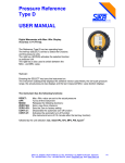
1
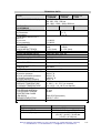
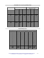
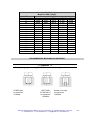
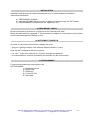
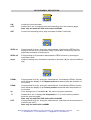
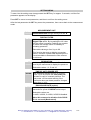
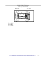
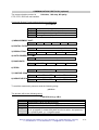
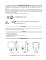
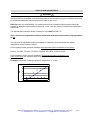
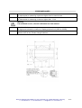
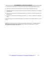
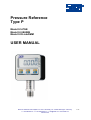
Pressure Reference
Type P
Model 0.5-PGE
Model 0.2-Bit02B
Model 0.05-LabDMM
USER MANUAL
SIKA Dr. Siebert & Kühn GmbH & Co. KG * Struthweg 7-9 * 34260 Kaufungen * Germany
℡ +49 5605-803-0 *
+49 5605-803-54 *
[email protected] * www.SIKA.net
V05-2014-09
1/17
GENERAL INDEX
INTRODUCTION
TECHNICAL DATA
STANDARD FULL SCALE and RESOLUTION
RECOMMENDED MECHANICAL MOUNTING
INSTALLATION
GENERAL KEYS DESCRIPTION
SETTING MENU
RS232C CONNECTIONS
COMMUNICATION PROTOCOL
BATTERY REPLACEMENT
DISPOSAL
OPTIONS
DIMENSIONS
FULL SCALE CALIBRATION
ERROR MESSAGES
SIKA has the right to make any change when necessary, without notice. Data enclosed in this
manual are just indicative and the manufacturer declines any responsibility for errors or
discrepancies contained in this manual.
SIKA Dr. Siebert & Kühn GmbH & Co. KG * Struthweg 7-9 * 34260 Kaufungen * Germany
℡ +49 5605-803-0 *
+49 5605-803-54 *
[email protected] * www.SIKA.net
2/17
INTRODUCTION
The digital gauges are made according to the more modern technologies in order to assure an high
level of reliability, versatility and inexpensiveness at the same time.
Its main applications develop in industrial fields where it is necessary to check processes or in
field, with a precision class better than up to 0.05%.
To increase the practicality and make the instrument completely autonomous, the pressure gauge
is fed by internal batteries which ensure round 1 year.
In the programming menu, reachable through the keyboard, it is possible to adjust different
functions such as:
• AUTO POWER OFF function which activates if within 30 minutes any pressure variations is
detected,
• digital filter that allows to maintain the measurement steady even in presence of unsteady
pressures,
• the display resolution which allows to increase the measurement at fixed steps (2, 5, 10)
and
• the measurement unit which can be changed into mbar, bar, kPa, MPa and psi.
The sensor, entirely executed in stainless steel, is monolithic to ensure a long term high stability
even in presence of highly dynamic pressures.
By selecting the reading of the TEMPERATURE (model 0.5-PGE and model 0.2-Bit02B) you can
see, on display, the temperature of the fluid that is in contact with the pressure sensor.
The new generation of digital manometers consist of a long term particularly steady analog section
and of A/D 16 bit converter, which guarantees a max of 65000 internal divisions.
The various versions are proposed for the different applications such as instruments for
metrological laboratories to be used as first or second line samples, for industrial applications for
data monitoring and transmission, for processes control or for testing material equipment, presses,
test benches etc..
The LCD display includes a pressure bar analog indication, always active also inside the
programming menu.
Main characteristics:
•
•
•
•
•
•
•
•
1 YEAR AUTONOMY WITHOUT RECHARGE
PROGRAMMABLE RESOLUTION
PROGRAMMABLE DIGITAL FILTER
ZERO FUNCTION
PEAK FUNCTION (positive and negative)
Temperature display (model 0.5-PGE, model 0.2 Bit02B)
PROGRAMMABLE BAUD RATE (option)
RS232C SERIAL OUTPUT (option)
SIKA Dr. Siebert & Kühn GmbH & Co. KG * Struthweg 7-9 * 34260 Kaufungen * Germany
℡ +49 5605-803-0 *
+49 5605-803-54 *
[email protected] * www.SIKA.net
3/17
TECHNICAL DATA
TYPE
RELATIVE PRESSURE (R)
LINEARITY and
HYSTERESIS
TEMPERATURE indication
a) Resolution
b) accuracy
TEMPERATURE EFFECT
per 1°C
a) on zero
b) on sensitivity
POWER SUPPLY
AUTONOMY
ALKALINE BATTERIES
INTERNAL RESOLUTION
PROG. MEASURE UNITS
PROGRAMM. RESOLUTION
PROGRAMM. BAUD RATE
ZERO FUNCTION
Model 0.05
Model 0.2
Model 0.5
- LabDMM
- Bit02B
- PGE
1 - 2.5 - 5 - 10 – 20 – 40 – 50 - 60 bar
100 -250 - 350 - 500 bar
700 -1000 - 1500 – 2000- 2500 bar
≤± 0.05 %
≤± 0.2 %
≤± 0.5 %
0.1 °C
≤ ±1 °C
≤±0.002%
≤±0.002%
Battery
BATTERY
1 year
1 YEAR
4x 1.5V (AAA)
2x 1.5V (AAA)
65.000 divs.
mbar, bar, MPa, kPa, psi
1, 2, 5, 10
19200, 9600, 4800
50% F.S.
PEAK FUNCTION
positive and negative
READINGS PER SEC.
Sampling rate
DISPLAY
MECHANICAL LIMIT VALUES
a) service pressure
b) max. permissible pressure
c) breaking pressure
d) highly dynamic pressure
REFERENCE TEMPERATURE
SERVICE TEMPERATURE
STORAGE TEMPERATURE
PROCESS COUPLING
TIGHTENING WRENCH
TIGHTENING TORQUE
PROTECTION CLASS
(EN 60529)
SENSOR EXECUTION
CASE EXECUTION
10
100 msec
16 mm custom LCD
OPTIONALS
Built-in version
SERIAL OUTPUT
VACUUM (V) range
100% F.S.
150% F.S.
>300% F.S.
75% F.S.
+23°C
0...50°C / -10...70°C (on request)
-10...60°C / -10...80°C (on request)
1/2" BSP MALE
27 mm
28 Nm
IP40 (IP65 front panel)
INOX 17-4 PH
Aluminium
Aluminium / IP65 front
RS232C - SUB D 9 pole FEMALE
(-1/+1) (-1/+2.5) (-1/+5) bar
(-1/+10) (-1/+20) (-1/+40) bar
(-1/+50) (-1/+60) bar
SIKA Dr. Siebert & Kühn GmbH & Co. KG * Struthweg 7-9 * 34260 Kaufungen * Germany
℡ +49 5605-803-0 *
+49 5605-803-54 *
[email protected] * www.SIKA.net
4/17
STANDARD FULL SCALE and RESOLUTION
Model 0.05 - LabDMM
Nominal Pressure Pressure
bar
bar
1
1.0000
2.5
2.5000
5
5.0000
10
10.000
20
20.000
40
40.000
50
50.000
60
60.000
100
100.00
250
250.00
350
350.00
500
500.00
700
700.00
1000
1000.0
1500
1500.0
2000
2000.0
2500
Resol.
bar
0.0001
0.0005
0.0005
0.001
0.002
0.002
0.005
0.005
0.01
0.02
0.05
0.05
0.05
0.1
0.2
0.5
Vacuum
bar
-1.0000
-1.0000
-1.0000
-1.0000
-1.0000
-1.0000
-1.0000
-1.0000
Model 0.2 - Bit02B
Model 0.5 - PGE
Pressure Resol.
Vacuum
bar
bar
bar
1.000
0.001
-1.000
2.500
0.001
-1.000
5.000
0.001
-1.000
10.00
0.01
-1.000
20.00
0.01
-1.000
40.00
0.01
-1.000
50.00
0.01
-1.000
60.00
0.01
-1.000
100.0
0.1
250.0
0.1
350.0
0.1
500.0
0.1
700.0
0.1
1000
1
1500
1
2000
1
2500
1
ENGINEERING UNITS
Nominal Pressure
bar
1
2.5
5
10
20
40
50
60
100
250
350
500
700
1000
1500
2000
2500
Model 0.05-LabDMM (5 digit)
Pressure unit / digits after decimal point
bar
mbar
kPa
MPa
PSI
1.0000
1000.0
100.00
0.1000
14.503
2.5000
2500.0
250.00
0.2500
36.259
5.0000
5000.0
500.00
0.5000
72.518
10.000
10000
1000.0
1.0000
145.03
20.000
20000
2000.0
2.0000
290.07
40.000
40000
4000.0
4.0000
580.15
50.000
50000
5000.0
5.0000
725.19
60.000
60000
6000.0
6.0000
870.23
100.00
10000
10.000
1450.4
250.00
25000
25.000
3625.9
350.00
35000
35.000
5076.3
500.00
50000
50.000
7251.9
700.00
70000
70.000
10152
1000.0
100.00
14503
1500.0
150.00
21755
2000.0
200.00
29007
SIKA Dr. Siebert & Kühn GmbH & Co. KG * Struthweg 7-9 * 34260 Kaufungen * Germany
℡ +49 5605-803-0 *
+49 5605-803-54 *
[email protected] * www.SIKA.net
5/17
Nominal Pressure
bar
1
2.5
5
10
20
40
50
60
100
250
350
500
700
1000
1500
2000
2500
Model 0.2-Bit02B (4 digit)
Model 0.5-PGE (4 digit)
Pressure unit / digits after decimal point
bar
mbar
kPa
MPa
PSI
1.000
1000
100.0
0.100
14.50
2.500
2500
250.0
0.250
36.26
5.000
5000
500.0
0.500
72.52
10.00
1000
1.000
145.0
20.00
2000
2.000
290.1
40.00
4000
4.000
580.2
50.00
5000
5.000
725.2
60.00
6000
6.000
870.2
100.0
10.00
1450
250.0
25.00
3626
350.0
35.00
5076
500.0
50.00
7252
700.0
70.00
1000
100.0
1500
150.0
2000
200.0
2500
250.0
RECOMMENDED MECHANICAL MOUNTING
WARNING
During the gauge mounting DO NOT force the case but tight with the wrench.
O-RING tight:
for pressures
<1000bar
USIT RING
12.70X18X1.5:
for pressures
<1000bar
Double cone tight:
for pressures
≥1000bar
SIKA Dr. Siebert & Kühn GmbH & Co. KG * Struthweg 7-9 * 34260 Kaufungen * Germany
℡ +49 5605-803-0 *
+49 5605-803-54 *
[email protected] * www.SIKA.net
6/17
INSTALLATION
Installation shall be done by authorized personnel only; for a fast installation follows the
instructions listed below:
a) PRELIMINARY CHECKS
b) Instrument POWER-ON and control of display functioning during the TEST phase.
c) PROGRAMMING (measurement unit, digital filter, etc.)
a) PRELIMINARY CHECK
Be sure that pressure provided is not higher than the instrument full scale.
Mount the manometer as suggested. If the manometer is installed in a oil-pressure circuit, please
perform the bleeding before starting to work.
b) INSTRUMENT POWER ON
At power on, the instruments execute a display test cycle:
- Verify the lighting of display, with software release indication (3 secs).
After this test it's displayed the input pressure:
- If a "LLLL" (lower limit reached) or a "UUUU" message are displayed,
it's recommended to conduce immediately the pressure into the correct range.
c) PROGRAMMING
Functions and parameters are grouped in this
SETTING MENU:
1) Measurement unit
2) Digital Filter
3) Resolution
4) Power Off Time
5) Baud Rate
SIKA Dr. Siebert & Kühn GmbH & Co. KG * Struthweg 7-9 * 34260 Kaufungen * Germany
℡ +49 5605-803-0 *
+49 5605-803-54 *
[email protected] * www.SIKA.net
7/17
KEYS GENERAL DESCRIPTION
ON
to switch on the manometer
OFF
Pressed for 5 sec. it performs the manual switching off of the pressure gauge
Note: only for model 0.5-PGE and model 0.2-Bit02B
SET
to enter into the setting menu (keep it pressed for about 3 seconds)
ZERO on
If kept pressed for 3 sec. during the measurement, it performs the ZERO of the
display in the first 50% of manometer range. ZERO does not have any effect on
graphic-bar indication of the pressure.
ZERO off
If kept pressed for 6 seconds it deactivates the ZERO function by showing the
manometer offset.
down
Inside the setting menu it allows the operator to decrease (▼) the values of defined
step.
PEAK+
If kept pressed for 2 sec. during the measurement, it activates the PEAK+ function,
which allows the display of the Highest pressure measured after the activation of
the function
PEAK-
If kept pressed for 4 sec. during the measurement, it activates the PEAK- function,
which allows the display of the Lowest pressure measured after the activation of
the function.
up
In the setting menu, it increases (▲) the values of a given parameter.
°C
Pressed for 6 sec. it displays the temperature in °C, to come back to pressure
press the same key again.
Note: only for model 0.5-PGE and model 0.2-Bit02B
OFF
If kept pressed for 5 sec. during the measurement, it switches off the manometer in
manual mode (OFF)
Note: only for model 0.05-LabDMM
SIKA Dr. Siebert & Kühn GmbH & Co. KG * Struthweg 7-9 * 34260 Kaufungen * Germany
℡ +49 5605-803-0 *
+49 5605-803-54 *
[email protected] * www.SIKA.net
8/17
SETTING MENU
To enter into the setting menu keep pressed the SET key for approx. 3 seconds, until the first
parameter appears on the display.
Press SET to move to next parameter, and then to exit from the setting menu.
After the last parameter the SET key saves the parameters, then comes back to the measurement
mode.
Unit
FL XX
MEASUREMENT UNIT
In this step it is possible to change the
measurement unit through the keys ▼ and ▲ .
DIGITAL FILTER
In this step the operator can change the
Digital Filter effect. By increasing the XX value
the filter effect increases. Enabling the operator
to detect the average value of unsteady or
pulsating pressures.
Selectable values go from 0 up to 99.
This function also acts on display conversion
speed, therefore if peaks shall be detected it is
recommendable to decrease the filter effect at
its minimum.
r XX
RESOLUTION
In this step it is possible to set the Resolution
used by the manometer to display the pressure.
Selectable values 1, 2, 5 and 10
oFFXX
bAUdX
TIME OF AUTO POWER OFF
This parameter defines the time in minutes
(from 1 up to 30) before the auto-power off
activates in case of constant pressure. The
auto-power off time starts working if the
manometer does not detect pressure changes
higher than +/-10%.
RS232 BAUD RATE (option)
In this step it is possible to program the
transmission speed of RS232C serial output
Selectable values are:
1=4800; 2=9600; 3=19200; 0=RS232 disabled.
Note: We recomend to disable of the RS232
if it is not used (Baud-rate=0).
SIKA Dr. Siebert & Kühn GmbH & Co. KG * Struthweg 7-9 * 34260 Kaufungen * Germany
℡ +49 5605-803-0 *
+49 5605-803-54 *
[email protected] * www.SIKA.net
9/17
RS232C CONNECTION (option)
Canon 9 pin SUB D female
Model A/B
PC - HOST
GND
TX
RX
DCD
Pin 1)
Pin 2)
Pin 3)
Pin 5)
DCD
RX
TX
GND
SIKA Dr. Siebert & Kühn GmbH & Co. KG * Struthweg 7-9 * 34260 Kaufungen * Germany
℡ +49 5605-803-0 *
+49 5605-803-54 *
[email protected] * www.SIKA.net
10/17
COMMUNICATION PROTOCOL (optional)
The communication protocol is
8 bit data, 1 bit stop, NO parity
CTS / RTS / DCD are not handled.
Command Strings Format and parameters programming
p n XX cr
p
n
XX
cr
the parameter strings starts with this character.
parameter number from 1 up to 8.
decimal value to be assigned to the parameter.
Carriage Return (13).
1) MEASUREMENT UNIT:
p1xxcr
00=psi
2) DIGITAL FILTER:
p2xxcr
01=MPa 02=kPa
03=bar
04=mbar
xx = values from 00 up to 99
3) RESOLUTION:
p3xxcr
00 = 1
4) AUTO POWER OFF TIME:
p4xxcr
01 = 2
02 = 5
03 = 10
xx = values from 01 up to 30 minutes
5) BAUD RATE:
p5xxcr
00=OFF
01=4800 02=9600
OFF disables the serial output
03=19200
6) ZERO:
p6xxcr
00 = ZERO OFF
01 = ZERO ON
7) POSITIVE PEAK:
p7xxcr
00 = PEAK+ OFF
01 = PEAK+ ON
8) NEGATIVE PEAK:
p8xxcr
00 = PEAK- OFF
01 = PEAK- ON
To read the manometer pressure send the following string:
p 0 00 cr
The answer will be the following string
s XX.XXX um z py LB cr
s
XX.XXX
um
z
py
LB
sign (ASCII character + or - )
measurement value with decimal point
measurement unit from 00 up to 04
if z is present, the it indicates that ZERO function is active
if in these two positions the optional chars
p+ or p- appear, it means that peak function is active, and precisely:
p+ = positive peak, p - = negative peak
If present indicates a low battery condition
SIKA Dr. Siebert & Kühn GmbH & Co. KG * Struthweg 7-9 * 34260 Kaufungen * Germany
℡ +49 5605-803-0 *
+49 5605-803-54 *
[email protected] * www.SIKA.net
11/17
BATTERY REPLACEMENT
The instrument is supplied with 2 (model 05-PGE and model 0.2-Bit02B) or 4 (model 0.05LabDMM) not rechargeable Alkaline batteries (AAA type 1.5V), with an average autonomy of 1
year.
Batteries consumption is signaled by the LO BAT icon, the measurements performed during this
phase could be altered: replace therefore the batteries. During this operation clean up the clips
contacts from possible oxydation and check the pressure exerted by external flaps on each battery:
please increase it if necessary.
Verify the electrical contact also in presence of malfunctions
ALKALINE battery pack must be
recycled or disposed properly.
WARNING:
If the instrument won’t be used for long time it is suggested to
REMOVE
batteries from manometer.
DISPOSAL
Delivery the instrument to company specialised in scrapping according to the laws in force in the
countries where the instrument is commercialised.
OPTIONS
•
•
•
•
SERIAL OUTPUT RS232C
STANDARD SERIAL CABLE
VACUUM OPTION (max. F.S. from -1 to +60 Bar)
panal mounting version
DIMENSIONS (mm)
SIKA Dr. Siebert & Kühn GmbH & Co. KG * Struthweg 7-9 * 34260 Kaufungen * Germany
℡ +49 5605-803-0 *
+49 5605-803-54 *
[email protected] * www.SIKA.net
12/17
FULL SCALE ADJUSTABLE
WARNING
This procedure is described in the manual by way of documentation only but it shall be performed
by authorised calibration centres only and in case of real need.
SIKA declines any responsibility for measurement errors or bad functioning which should be
caused by adjustment performed not properly. In this case the validity of manometer certification
would lose.
The adjustment procedure allows correction of up to ±30% of the F.S.
Note: the full scale adjustment shall be performed with the measurement unit programmed
in bar.
The full scale is adjusted through a procedure of calibration by points which also allows
linearisation of the pressure sensor.
On the positive scale (pressure reading) the manometer has to autolearn all the points:
P0=0%, P1=20%, P2=40%, P3=60%, P4=80%, P5=100% of the full scale.
On the negative scale (vacuum readings) the manometer has to autolearn only
point P6 at -1bar (the negative scale is an optional feature).
Example: Reference P having a pressure range from -1…5 bar
P5
5
P4
4
P3
bar
3
P2
2
P1
1
0
P0
P6
-1
SIKA Dr. Siebert & Kühn GmbH & Co. KG * Struthweg 7-9 * 34260 Kaufungen * Germany
℡ +49 5605-803-0 *
+49 5605-803-54 *
[email protected] * www.SIKA.net
13/17
Positive full scale adjustment
8.8.8.8.8
P0000
Per X
P0
P1
P2
P3
P4
P5
P6
dP
Switch on the manometer (ON) and keep the SET and PEAK keys
pressed together (during the TEST phase)
Set the password 3124 using the ▲ and ▼ keys
confirm with the SET key
~ Set at 1
if the full scale to be programmed does not exceed 65000 div.
~ Set at 2
if the full scale to be programmed exceeds 65000 div.
Note: Since the manometer is supplied calibrated, adjustment
of this parameter is not necessary.
Vary with the ▲ and ▼ keys
confirm with the SET key
Bring the manometer to 0 bar by opening the pressure circuit
confirm the pressure setting with the SET key
If the manometer displays an offset, then make a reset by using
the ZERO key
confirm with the SET key
Bring the manometer to 20% F.S. of the pressure
confirm the pressure setting with the SET key
Adjust the reading by using the ▲ and ▼ keys
confirm with the SET key
Bring the manometer to 40% F.S. of the pressure
confirm the pressure setting with the SET key
Adjust the reading by using the ▲ and ▼ keys
confirm with the SET key
Bring the manometer to 60% F.S. of the pressure
confirm the pressure setting with the SET key
Adjust the reading by using the ▲and ▼keys
confirm with the SET key
Bring the manometer to 80% F.S. of the pressure
confirm the pressure setting with the SET key
Adjust the reading by using the ▲and ▼keys
confirm with the SET key
Bring the manometer to 100% F.S. of the pressure
confirm the pressure setting with the SET key
Adjust the reading by using the ▲and ▼keys
confirm with the SET key
To complete the adjustment of the positive measuring range
confirm with the SET key
without performing any correction on point P6.
Note: only available at model 0.05-LabDMM
Negative Full Scale adjustment procedure
Bring the manometer to –1 bar and confirm with the SET key.
Adjust the reading with the
and
keys
confirm with the SET key
In this phase the decimal point has to be set.
Confirm with the SET key, move the decimal point using
the ▲ and ▼ keys
confirm with the SET key
SIKA Dr. Siebert & Kühn GmbH & Co. KG * Struthweg 7-9 * 34260 Kaufungen * Germany
℡ +49 5605-803-0 *
+49 5605-803-54 *
[email protected] * www.SIKA.net
14/17
Positive full scale adjustment
for model 0.5-PGE and modell 0.2-Bit02B
8.8.8.8.8
P0000
Per X
-P0
-P1
-P2
-P3
-P4
-P5
dP
Switch on the manometer (ON) and keep the SET and PEAK keys
pressed together (during the TEST phase)
Set the password 2124 using the ▲ and ▼ keys
confirm with the SET key
~ Set at 1
if the full scale to be programmed does not exceed 65000 div.
~ Set at 2
if the full scale to be programmed exceeds 65000 div.
Note: Since the manometer is supplied calibrated, adjustment
of this parameter is not necessary.
Vary with the ▲ and ▼ keys
confirm with the SET key
Bring the manometer to 0 bar by opening the pressure circuit
confirm the pressure setting with the SET key
If the manometer displays an offset, then make a reset by using
the ZERO key
confirm with the SET key
Bring the manometer to -0.2 bar (20% F.S.)
confirm the pressure setting with the SET key
Adjust the reading by using the ▲ and ▼ keys
confirm with the SET key
Bring the manometer to -0.4 bar (40% F.S.)
confirm the pressure setting with the SET key
Adjust the reading by using the ▲ and ▼ keys
confirm with the SET key
Bring the manometer to -0.6 bar (60% F.S.)
confirm the pressure setting with the SET key
Adjust the reading by using the ▲and ▼keys
confirm with the SET key
Bring the manometer to -0.8 bar (80% F.S.)
confirm the pressure setting with the SET key
Adjust the reading by using the ▲and ▼keys
confirm with the SET key
Bring the manometer to -1 bar (100% F.S.)
confirm the pressure setting with the SET key
Adjust the reading by using the ▲and ▼keys
confirm with the SET key
In this phase the decimal point has to be set.
Confirm with the SET key, move the decimal point using
the ▲ and ▼ keys
confirm with the SET key
SIKA Dr. Siebert & Kühn GmbH & Co. KG * Struthweg 7-9 * 34260 Kaufungen * Germany
℡ +49 5605-803-0 *
+49 5605-803-54 *
[email protected] * www.SIKA.net
15/17
ERROR MESSAGES
UUUU
-LLLL
Positive Overload
the manometer is measuring a pressure higher than its nominal rate.
Negative Overload
the manometer is measuring a vacuum higher than –1 bar
Warning
if an overload occurs, check if calibration has been altered.
HHHH
LbAt
Out of the Scale
the instrument shows the overflow of display physical limit (9999 or 99999).
Low Battery
batteries level is low. Please change batteries
SIKA Dr. Siebert & Kühn GmbH & Co. KG * Struthweg 7-9 * 34260 Kaufungen * Germany
℡ +49 5605-803-0 *
+49 5605-803-54 *
[email protected] * www.SIKA.net
16/17
RECOMMENDED CALIBRATION ROCEDURE
a) Carry out three cycles to the Full Scale of the manometer for checking (preloading cycles).
b) Take the zero measurements at atmospheric pressure with the discharge valve open.
c) Generate the pressure, taking the sample manometer as reference, and take the two readings
simultaneously.
d) Record the measurements at increasing pressures (e.g. 5 points) to evaluate the linearity and
reading errors.
e) Record the measurements at decreasing pressures (e.g. 5 points) to evaluate the hysteresis
errors.
Discharge the system by opening the discharge valve and take the manometer readings on return
to zero.
SIKA holds the right to make any change when necessary, without notice. The data contained in
this manual are just indicative and the manufacturer declines any responsibility for errors or
discrepancies with respect to this manual.
SIKA Dr. Siebert & Kühn GmbH & Co. KG * Struthweg 7-9 * 34260 Kaufungen * Germany
℡ +49 5605-803-0 *
+49 5605-803-54 *
[email protected] * www.SIKA.net
17/17