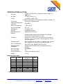
1
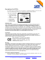
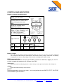
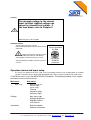
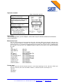
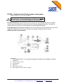
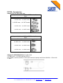
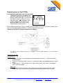
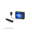
PC700+
Pressure Calibrator
USER MANUAL
PC700+ Pressure Calibrators
User’s Manual ver. 01-2004 MANP017
All rights reserved © 2004, SIKA
SIKA, Dr. Siebert & Kühn GmbH & Co. KG, Struthweg 7-9, 34260 Kaufungen, Germany
Tel: +49-5605-803-0, Fax: +49-5605-803-54, email: [email protected], web: www.SIKA.net
1/18
Thank you for purchasing our pressure meter.
This product is manufactured in accordance with our strict standards for quality in design, components, and
workmanship to fulfill our vision:
“To be the leading company in high quality self-contained products”
SIKA reserves the right to make improvements or alterations to their products without incurring any
responsibility to make the same improvements or alterations to products previously sold.
© SIKA.
All rights reserved. No part of this publications may be reproduced, stored in a retrieval system, or
transmitted in any form by any means, electronic, mechanical, photocopying, recording, or
otherwise without the prior permission of SIKA.
All efforts have been made to ensure the accuracy of this handbook. We at SIKA are always striving to
improve our products and handbooks, therefore we would greatly appreciate being informed of any errors
found in our product or its handbook. The above notwithstanding, SIKA can assume no responsibility for any
errors in this handbook or the consequences.
Symbol used to identify an action that can cause
personal injury or damage to equipment.
Always release internal pressure at connectors
before disconnecting.
Uncontrolled release of high pressure can result in
personal injury and damage to equipment.
SIKA, Dr. Siebert & Kühn GmbH & Co. KG, Struthweg 7-9, 34260 Kaufungen, Germany
Tel: +49-5605-803-0, Fax: +49-5605-803-54, email: [email protected], web: www.SIKA.net
2/18
Table of Contents
1
DESCRIPTION OF THE PC700+ ........................................................................................................4
1.1
1.2
1.3
1.4
1.5
1.6
1.7
2
CALIBRATION LABEL ....................................................................................................................4
CERTIFICATION.............................................................................................................................4
WARRANTY....................................................................................................................................4
CONVENTIONS USED IN THIS DOCUMENT ...............................................................................4
SAFETY PRECAUTIONS ...............................................................................................................5
BATTERY CHARGING INFORMATION.........................................................................................5
PC700+ NOT OPERATING/FAILED ..............................................................................................5
CONTROLS AND INDICATORS.........................................................................................................6
2.1
2.2
2.3
2.4
2.5
2.6
2.7
2.8
3
DISPLAY, CONTROLS AND CONNECTIONS ..............................................................................6
BATTERY CHARGER.....................................................................................................................6
RS232 COMMUNICATION.............................................................................................................6
SWITCH TEST................................................................................................................................6
VOLTAGE .......................................................................................................................................6
GROUND ........................................................................................................................................6
CURRENT.......................................................................................................................................7
EXTERNAL SENSOR .....................................................................................................................7
OPERATION MENUS AND INPUT SETUP ........................................................................................7
3.1
3.2
OPERATION CONTROLS..............................................................................................................8
INPUT SETUP ................................................................................................................................8
3.2.1
3.2.2
3.2.3
3.2.4
3.2.5
3.2.6
3.3
SETTINGS ......................................................................................................................................9
3.3.1
3.3.2
3.3.3
3.3.4
3.4
Main view type .........................................................................................................................................................9
Backlight brightness............................................................................................................................................... 10
Backlight timeout ................................................................................................................................................... 10
LCD contrast.......................................................................................................................................................... 10
INFORMATION .............................................................................................................................10
3.4.1
3.4.2
3.5
Measurement unit ....................................................................................................................................................8
Sensor input ............................................................................................................................................................8
Sensor range ...........................................................................................................................................................9
Filtering....................................................................................................................................................................9
Number of digits.......................................................................................................................................................9
Reference input .......................................................................................................................................................9
Reference details................................................................................................................................................... 10
Software information .............................................................................................................................................. 10
HISTORY LOG..............................................................................................................................10
3.5.1
3.5.2
3.5.3
3.5.4
Enter sensor name ................................................................................................................................................ 10
View stored sensors............................................................................................................................................... 11
Delete one sensor.................................................................................................................................................. 11
Delete all ............................................................................................................................................................... 11
4
GETTING STARTED .........................................................................................................................11
5
SPECIFICATIONS OF PC700+ .........................................................................................................12
6
PC700+, HYDRAULIC HAND-HELD PRESSURE TEST SYSTEM .................................................14
6.1
6.2
7
PC700+ CONTROLS AND ORIENTATION..................................................................................14
OPERATION OF THE PC700+.....................................................................................................15
PC700+ ACCESSORIES ...................................................................................................................16
7.1
8
ADAPTERS FOR THE ITEM UNDER TEST ................................................................................16
REPLACING FUSE IN THE PC700+ ................................................................................................17
8.1
8.2
FAULT FINDING TO DETERMINE IF THE FUSE HAS BLOWN.................................................17
PC700+, INSTRUCTIONS FOR REPLACING THE FUSE OR BATTERY ..................................17
SIKA, Dr. Siebert & Kühn GmbH & Co. KG, Struthweg 7-9, 34260 Kaufungen, Germany
Tel: +49-5605-803-0, Fax: +49-5605-803-54, email: [email protected], web: www.SIKA.net
3/18
Description of the PC700+
The PC700+ Pressure Calibrator series are designed as self-contained, portable pressure meters that
have been calibrated to precision pressure equipment traceable to national standards.
Each unit is marked with:
• Certificate Number
• Safety code and gas
group
• Calibration certificate
• Serial number
• Production year
• Pressure range.
Calibration label
SIKA certifies that this product meets published specifications at the time of shipment from the
factory. SIKA further certifies that its calibration measurements are traceable to accredited
international standards. Each pressure calibrator has a calibrated label showing the last date of
calibration and the date when the next calibration is due. Calibration is scheduled annually, unless
you believe the unit to be defective, whereupon the unit will be calibrated after repair and receive a
new label showing the date calibrated and the new calibration-due date. Check the calibrated label
to ensure the Pressure Meter Calibrator has a valid calibration date before using the unit.
Calibration must be done by SIKA or a certified supplier/service center.
Certification
SIKA certifies that the PC700+ comply with its published list of specifications at the time it was
manufactured. SIKA also certifies that its calibration measurements are traceable to to the
calibration facilities of other International Standards Organization (ISO) members. SIKA confirms
that the PC700+ complies with the following standards:
EMC 89/336/EEC as amended by EC Directive
92/31/Eec and the European Low Voltage Directive
73/25/EEC, amended by 93/68/EEC. To ensure
compliance, please use screened/shielded serial
communication leads (RS232).
Warranty
This product is guaranteed free from defects in material and workmanship for one (1) year from the
date of shipment. During this warranty period, SIKA will, at its option, either repair or replace the
PC700+ should it prove to be defective. The product must be returned to a service facility
designated by SIKA for warranty service or repair. The foregoing warranty will not apply to defects
resulting from improper maintenance by the purchaser, purchaser-supplied software or interfacing,
unauthorized modification or misuse, operation exceeding the environmental specifications for the
PC700+, or improper site preparation. No other warranty is expressed or implied by SIKA, and
SIKA shall not be liable for any direct, indirect, special, incidental or consequential damages,
whether based on contract, tort, or any other legal theory.
Conventions used in this document
We have provided this section of the Handbook to help you identify noteworthy symbols, terms and
conventions used in this handbook. Look for the following:
SIKA, Dr. Siebert & Kühn GmbH & Co. KG, Struthweg 7-9, 34260 Kaufungen, Germany
Tel: +49-5605-803-0, Fax: +49-5605-803-54, email: [email protected], web: www.SIKA.net
4/18
Symbol used to
identify an action that
can cause personal
injury or damage to
equipment.
Conformité
Européenne
Terms and definitions:
We define calibration as being
able to compare the ability of
the equipment to perform to a
known standard. Pressure
calibration provides a means of
quantifying uncertainties in
pressure measurement in order
to optimize sensor and/or
system accuracy.
Safety precautions
Following these safety precautions should ensure safe operation of the pressure meter and your
personnel safety. Be careful when working in hazardous areas as any electrical spark could result in
an atmospheric explosion/fire.
•
Do not use the instrument at ambient temperatures above 50°C.
•
•
•
•
Do not connect to RS232 port in hazardous area.
Do not apply voltage to the CURRENT input terminal.
Do not remove the rear panel.
Connect only SIKA manufactured sensors to the External Sensor connector.
Battery charging information
• Do not charge battery in hazardous areas.
• Use only the battery charger supplied by SIKA
From a completely discharged condition, battery-charging time is about 14 hours, at a maximum
charging current of 65mA.
When the battery is charged, it will provide power for about 35 hours of continuous operation if the
display back-light is defined as OFF, (and with no RS232 connection).
In safe areas, the Pressure Meter Calibrator can be operated with all Inputs and Outputs, and with
the battery charger connected. The Battery Charging time will increase depending on connections
and display back-light settings.
PC700+ not operating/failed
Repairs must be done by manufacturer or supplier certified for service/repair of intrinsically safe
equipment. Replacement batteries and fuses must be obtained from the manufacturer.
SIKA, Dr. Siebert & Kühn GmbH & Co. KG, Struthweg 7-9, 34260 Kaufungen, Germany
Tel: +49-5605-803-0, Fax: +49-5605-803-54, email: [email protected], web: www.SIKA.net
5/18
CONTROLS AND INDICATORS
Display, controls and connections
ON/OFF button
Power on or off control
CANCEL
Used to cancel an action and to
move to the previous menu
level.
Display
Shows the available menu
selections or values.
MENU SELECTION
Allows selection of menu item to read,
change or define information, or to
select the next level of sub-menu.
move UP the menu.
move DOWN the menu.
Input Terminals
SW
mA
Switch
test
V
Voltage
Gnd
Current
B.c
.
Battery
charger
RS232
Ground
(common)
serial
communication
DO NOT charge battery or connect to RS232 in a hazardous area.
Battery charger
Connection for the Battery Charger provided by SIKA. In safe areas, the Pressure Meter Calibrator
can be operated with all Inputs and Outputs, and with the battery charger connected. The Batterycharging time will increase depending on connections and display back-light settings.
RS232 communication
Serial RS232 connection for interfacing the PC700+ to allow menu definition, logging, etc. via PC
or other computer-based device with software from SIKA.
switch test
Input connection for indicating when the switch changes state (open-to-closed or closed-to-open).
voltage
Input connection for voltage measurement.
ground
Reference ground for the pressure meter. Use in conjunction with the SWITCH-TEST, VOLTAGE,
and CURRENT input connectors.
SIKA, Dr. Siebert & Kühn GmbH & Co. KG, Struthweg 7-9, 34260 Kaufungen, Germany
Tel: +49-5605-803-0, Fax: +49-5605-803-54, email: [email protected], web: www.SIKA.net
6/18
current
Do not apply voltage to the current
input terminal. Applied voltage can
cause the internal fuse to blow. If
the fuse blows, refer to Chapter 0
Replacing fuse in the PC700+.
external sensor
Connect only reference sensors
manufactured by SIKA to the External Sensor
connector.
Always replace the cap/cover when
not in use and power OFF the unit before
connecting the external reference sensor.
Contact SIKA for available external reference
sensors.
ONLY connect
sensors provided
by SIKA
ENTERNAL
SENSOR
connector
Operation menus and input setup
The menus are organized in levels, with each level leading to lower-levels of information or available
selections. At power-up, the display will INITIALIZE and restore previously defined and saved values.
To VIEW the menus, press the MENU SELECTION button. The following headings in this chapter
describe the menus and sub-menus.
Main menu
Sub-menus
Input setup
Measurement unit
Sensor input
Sensor range
Filtering
Number of digits
Reference input
Settings
Main menu type
Backlight brightness
Backlight timeout
LCD contrast
Information
Reference details
Software information
SIKA, Dr. Siebert & Kühn GmbH & Co. KG, Struthweg 7-9, 34260 Kaufungen, Germany
Tel: +49-5605-803-0, Fax: +49-5605-803-54, email: [email protected], web: www.SIKA.net
7/18
Operation controls
Menu interaction controls
ON/OFF button
Power on or off control
CANCEL
Used to cancel an action and to
move to the previous menu
level.
Display
Shows the available menu
selections or values.
MENU SELECTION
Allows selection of menu item to read,
change or define information, or to
select the next level of sub-menu.
move UP the menu.
move DOWN the menu.
Input setup
This menu group allows you to configure, select and set up all reference and external reference
sensor information.
Measurement unit
You can select the desired measurement unit in this sub-menu. When you enter this sub-menu, the
active unit will be shown as selected. The selected new unit will be applied to both the internal and
external reference. It is possible to change from bar to any other unit. The bar value is multiplied with
the respective constant. Press the CANCEL button to return to the previous menu without changing
the value:
• bar
• kPa (kN/m2)
• MPa (MN/m2)
• atm
• psi (lbf/in2)
• at (kgf/cm2)
• torr (mmHg) at 0°C
• mHg at 0°C
• inHg at 32°F
• cmH2O at 4°C
• mH2O at 4°C
• inH2O at 39.2°F
1E5/1E3
1E5/1E6
1E5/1.01325E5
1E5/6.89475729317E3
1E5/9.80665E4
1E5/1.33322368421E2
1E5/1.33322368421E5
1E5/3.38638815789E3
1E5/9.80638E1
1E5/9.80638E3
1E5/2.4908891E2
Sensor input
You can select the desired external reference sensor input signal-type in this sub-menu. When you
enter this sub-menu, the active unit will be shown as selected. Possible sensor inputs are:
• 0-15 V
• 0-100 mV
• 0-30 mA
SIKA, Dr. Siebert & Kühn GmbH & Co. KG, Struthweg 7-9, 34260 Kaufungen, Germany
Tel: +49-5605-803-0, Fax: +49-5605-803-54, email: [email protected], web: www.SIKA.net
8/18
Sensor range
You can use this sub-screen to set up how the external reference sensor input electrical signal should
be converted to pressure. To do this, you set a low and high electrical value equal to a low and highpressure value. It is possible to edit both electrical and pressure values.
Filtering
You can select delay between each time the sensor and reference is sampled and updated in this
sub-menu. When you enter this sub-menu, the active unit will be shown as selected. (The
respective constant is the number of samples needed to take an average): Possible filter settings
are:
• Fast
2
• Medium
5
• Accurate
10
Number of digits
In this sub-menu, you can select the numbers of the digits you want to view on the sensors and
references. When you enter this sub-menu, the active unit will be shown as selected. Possible
selections are:
• 3 numbers
• 4 numbers
• 5 numbers
Reference input
•
•
•
You can select the reference input in this sub-menu. When you enter this sub-menu, the active unit
will be shown as selected. Possible selections are:
Automatic
(use the external reference if it is present during power-up, otherwise use the internal reference)
Internal
(use the internal reference)
External
(use the external reference)
Settings
This menu group allows you to configure the PC700+ device settings that do not affect the sensor or
the reference.
Main view type
You can select how the Main Menu will look from this sub-menu. When you enter this sub-menu, the
active unit will be shown as selected. The illustration below shows the LCD with explanations and
possible selections:
Normal
Error in unit
Ref value (in unit)
Measurement unit
MENU
Sensor value (in mA or Volts)
Sensor value (in unit)
Sw:OFF
III
II
I
battery
Maximum in unit
Measurement unit
Ref value (in unit)
Minimum in unit
MENU
Min and max
Maximum in unit
Sensor value (in unit)
Minimum in unit
III
II
I
battery
Switch and leak
Reading per hour/minute/day
Ref value (in unit)
Measurement unit
MENU
OFF:--Sensor value (in unit)
ON:---
III
II
I
battery
SIKA, Dr. Siebert & Kühn GmbH & Co. KG, Struthweg 7-9, 34260 Kaufungen, Germany
Tel: +49-5605-803-0, Fax: +49-5605-803-54, email: [email protected], web: www.SIKA.net
9/18
Backlight brightness
You can adjust the brightness of the LCD back-light in this sub-menu. The hardware supports 8
different levels. High back-light brightness can severely reduce battery discharge time.
Backlight timeout
You can select back-light timeout in this sub-menu. When you enter this sub-menu, the active unit will
be shown as selected. Possible selections are:
• Always off (no battery used for back-light)
• 2 seconds
• 5 seconds
• 10 seconds
• 20 seconds
• 1 minute
• Always on (battery used to provide back-light)
Selecting “Always on” as the backlight timeout will severely consume battery power.
LCD contrast
You can adjust the contrast of the LCD in this sub-menu.
High LCD contrast will slightly consume battery power.
Information
You can view the PC700+ information in this menu group.
Reference details
This tells you information about the reference you have selected (refer to "Input setup" and "reference
input" chapters). The following information is shown:
• Serial number
• Sensor pressure range
• Calibration date
Software information
There are two software items with related information. The first one (to the left on each line) refers to
the main micro-controller in the PC700+, which controls the external RS-232 port, the LCD and user
input. The second (to the right on each line) refers to the internal sensor reference ADC microcontroller. The following Information is shown:
• Baud rate (communication speed)
• Communication protocol addresses
• Software versions
History log
This menu group allows you to store, view and delete log information in the PC700+. The stored loginformation is sensor name, related input setup, switch-state and pressure values for reference and
sensor. It is possible to store up to 30 groups of information ("connected" to a “sensor name”), and up
to 10 pressure points (reference, sensor and switch-state).
Enter sensor name
You must enter a sensor name before you can log information. Both alphabetical and numeric
characters are available, and up to 8 characters can be used in a sensor name. When you have
configured
the input setup and entered the sensor name, pressing the Log Button when in Main view will store
information to the history log. A specific input setup is connected to each sensor name, and if this
input setup is modified after the information is logged, a new sensor name is required.
SIKA, Dr. Siebert & Kühn GmbH & Co. KG, Struthweg 7-9, 34260 Kaufungen, Germany
Tel: +49-5605-803-0, Fax: +49-5605-803-54, email: [email protected], web: www.SIKA.net
10/18
View stored sensors
Select this menu-item to view logged sensor names, connected input setup, switch-state and
pressure values.
Delete one sensor
This menu item allows you to select one sensor name for removal from the history log. All
information connected to this sensor-name will be removed.
Delete all
All history-log information will be removed if this menu item is selected. You will be prompted to ensure
that this is not done accidentally.
Getting started
This section contains a description of the PC700+ operator control and connection points to help
you to get started quickly.
Operation controls and connections
Very little operator interaction is required to begin a calibration. The main operator interaction is via
the unit’s buttons and display, or via a (local) PC or other remote computer. Communication with the
PC is via the unit’s RS232 serial port connector. To begin a calibration, you must:
1.
Connect the external reference sensor (if it is to be used)
2.
Connect the meter or sensor to be tested. Refer to Chapters Fehler! Verweisquelle
konnte nicht gefunden werden. for information about the type of pump being used.
3.
Power the unit ON.
4.
5.
Configure the sensor to be tested.
Connect the sensor leads to the appropriate input connector. Refer to Chapters
Fehler! Verweisquelle konnte nicht gefunden werden. for information.
6.
Set the pressure using the pressure pump
End of procedure.
SIKA, Dr. Siebert & Kühn GmbH & Co. KG, Struthweg 7-9, 34260 Kaufungen, Germany
Tel: +49-5605-803-0, Fax: +49-5605-803-54, email: [email protected], web: www.SIKA.net
11/18
SPECIFICATIONS of PC700+
Accuracy
± 0.03% FS (10–40°C), temperature effects: 0.001% of
reading/°C
mA input
V input
0–30mA (± 0.03% FS.)**
0–15VDC (± 0.05% FS.)**
** Ambient temperature 25°C, temperature effects: ± 0.008%/°C.
History log
30 sensors, 10 points each
Operating temperature
0 to +50°C
(ambient)
Process temperature
–20 to +80°C
Pressure overload
FS x 1.5
Wetted parts
Hastelloy C-22
Housing
Anodized aluminum
Operating time on
Approximately 35 hours
batteries
Programmable: Input mA/mV/V/Switch Test, Range,
Conversion, Engineering Units, Filter.
Functions
Min/Max/Tare, History Log, Internal/External Sensor, Battery
Indicator, Leak Test, Selectable Language (optional), Remote
Operation (optional).
Engineering unit
EEx / IS certification
ATEXproduction
notification
Pressure range
Pressure media
Overall dimensions
Weight
Bar, kPa, Mpa, atm, psi (lb/in²), at (kgf/cm²), torr, mHg at
0°C, inHg at 32°F, cmH2O at 4°C, inH2O at 39.2°C
Exe ia IIC T4 , NEMKO 02ATEX 1374X
NEMKO 02ATEX445Q ATEX according to directive
94/9/EC
0 to 700 Bar
Oil
345 x 160 x 180 mm (w-h-d)
8.1 kg
Maximum input rating
Input
Range
Pressure 0 - 20
Pressure 0 - 40
Pressure 0 - 80
Pressure 0 -150
Pressure 0 - 300
Pressure 0 - 600
Pressure 0 - 1200
Voltage
0 - 15
Current * 0 - 30
* Input is protected by 50 mA fuse
Absolute
maximum
30
60
120
225
450
900
1800
19
40
Unit
Bar
Bar
Bar
Bar
Bar
Bar
Bar
VDC
mADC
SIKA, Dr. Siebert & Kühn GmbH & Co. KG, Struthweg 7-9, 34260 Kaufungen, Germany
Tel: +49-5605-803-0, Fax: +49-5605-803-54, email: [email protected], web: www.SIKA.net
12/18
When returning a product, please provide the following information,
1.
Product name
2.
Serial number
3.
Details of defect/work to be undertaken
4.
Operating conditions
5.
Tell us if the product has been in contact with anything hazardous or toxic and the
relevant COSHH references and precautions to be taken when handling.
SIKA, Dr. Siebert & Kühn GmbH & Co. KG, Struthweg 7-9, 34260 Kaufungen, Germany
Tel: +49-5605-803-0, Fax: +49-5605-803-54, email: [email protected], web: www.SIKA.net
13/18
PC700+, Hydraulic hand-held pressure test system
Provides hydraulic pressure of 0 to 700 bar
Always release the internal pressure at connectors before
disconnecting. Uncontrolled release of high pressure can
result in personal injury and damage to the equipment.
Reservoir-fluid level: If the fluid level in the reservoir falls considerably during use, a partial
vacuum may be created in the reservoir that can affect the pump performance. To avoid this,
simply allow air to enter the reservoir by partly unscrewing the filling plug.
Seal replacement: Depending on frequency of use, the main piston seal (and others) may need
replacing. Replacement seals and instructions for fitting are contained in the seal kit
PC700+ Controls and orientation
Drawing key:
1
Pressure port: M16 x 1.5 mm quick connector for flexible hose to adapters and item
under test.
2
3
4
5
6
Pressure release valve
Pump handle.
Filling cap
Main pressure valve
Fine-adjustment valve (volume control).
SIKA, Dr. Siebert & Kühn GmbH & Co. KG, Struthweg 7-9, 34260 Kaufungen, Germany
Tel: +49-5605-803-0, Fax: +49-5605-803-54, email: [email protected], web: www.SIKA.net
14/18
Operation of the PC700+
Refer to the orientation drawing to locate the controls.
1. Lift the pump handle. Remove the filling plug and fill the reservoir to 6mm level with the
recommended fluid. Replace the filling plug.
2. Connect the instrument under test to the flexible hose/gauge adapter and attach it to the pump
via the quick-fit connection.
3.
4.
5.
6.
7.
8.
Adjust the main-pressure valve and fine-adjustment valve to mid-travel.
Ensure that the pressure-release valve is open (turn fully clockwise, then one turn
counter-clockwise).
Operate the pump handle several times to expel air from the pump.
Close the pressure-release valve fully clockwise.
Prime the system by pumping the handle to allow the oil to enter the pump cylinder.
Repeat as necessary until the system is fully primed and low pressure is indicated on
either the master or the test instrument.
Close the main-pressure valve.
Adjust the pressure to the required value using the fine-adjustment valve.
Note: The pressure will fall slightly, immediately after pressure generation due to the thermodynamic
effect but will stabilize after a short time.
DO NOT EXCEED the maximum operating pressure
indicated on the pump label!
9.
To totally release pressure from the system, turn the pressure-release valve and the
main-pressure valve one turn counterclockwise (the pump handle can be operated
without pressure resistance).
Note: Careful use of the release valve, main-pressure valve ➄ and fine-adjustment valve ➅
enables a controlled release of pressure, essential for calibration purposes.
10. End of operation procedure.
SIKA, Dr. Siebert & Kühn GmbH & Co. KG, Struthweg 7-9, 34260 Kaufungen, Germany
Tel: +49-5605-803-0, Fax: +49-5605-803-54, email: [email protected], web: www.SIKA.net
15/18
PC700+ Accessories
Adapters for the item under test
Adapter kit 1, ¼-inch BSP to NPT Female, Carbon
Steel
Description
drawing
1/4" BSP male – 1/8" NPT female
1/4" BSP male – 1/4" NPT female
1/4" BSP male – 3/8" NPT female
1/4" BSP male – 1/2" NPT female
Adapter kit 2, ¼-inch BSP to BSP Female, Carbon
Steel
Description
drawing
1/4" BSP male –- 1/8" BSP female
1/4" BSP male – 3/8" BSP female
1/4" BSP male – 1/2" BSP female
Adapter kit 4C BSP-BSP Swivel, Carbon Steel
1/4" BSP male – 1/4" BSP male for 5PV-411
For PC700+; connects to M16 x1.5mm quick connect at pump and to item with M16 x 1.5mm with
¼” BSP.
SIKA, Dr. Siebert & Kühn GmbH & Co. KG, Struthweg 7-9, 34260 Kaufungen, Germany
Tel: +49-5605-803-0, Fax: +49-5605-803-54, email: [email protected], web: www.SIKA.net
16/18
Replacing fuse in the PC700+
Fault finding to determine if the fuse has blown
To determine if the fuse has blown, use a
multimeter and measure the resistance
between GND and A input. The resistance
must be less than (>) 25 Ohms. Use a
multimeter with a test voltage less than
2.5VDC (otherwise, the internal 2.7V
protecting diodes may cause a faulty
Ohm/resistance measurement).
When ordering spare parts, always include the serial number of the faulty instrument. Battery and
fuses must be obtained from SIKA or a certified supplier/service center.
PC700+, instructions for Replacing the fuse or battery
If needed, request original drawing no. SA00325; Title Assembly drawing, Fuse and Battery
replacement.
Replacing Fuse F01.
Remove Fuse,
1. Unscrew 4 screws in the side-panel and remove panel carefully. 2 wires from battery
are connected.
2. The fuse is now accessible. The fuse is marked with 50mA and plugged between 2 black
wires.
3. Locate the fuse. Then, pull out the fuse-legs from the wires (the 2 wires are supplied
with a small connector).
New Fuse
4. Connect the new fuse to the 2 wires and put the wires back into the housing. When
everything is OK, the side-panel can be remounted and secured with the 4 screws.
SIKA, Dr. Siebert & Kühn GmbH & Co. KG, Struthweg 7-9, 34260 Kaufungen, Germany
Tel: +49-5605-803-0, Fax: +49-5605-803-54, email: [email protected], web: www.SIKA.net
17/18
Replacing the Battery
1.
2.
Unscrew 4 screws in the side-panel and remove panel carefully. 2 wires, red and black,
from battery are connected.
Disconnect wires. Mini connector.
Remove the 4 screws holding the battery pack to the side-panel. Lift off the old battery and replace it
with a new. Secure the new battery with the 4 screws.
3.
4.
Connect the battery.
Remount the back panel and secure with 4 screws.
If needed, follow instructions for charging.
SIKA, Dr. Siebert & Kühn GmbH & Co. KG, Struthweg 7-9, 34260 Kaufungen, Germany
Tel: +49-5605-803-0, Fax: +49-5605-803-54, email: [email protected], web: www.SIKA.net
18/18