1
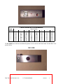
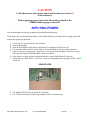
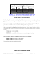
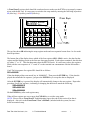
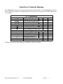
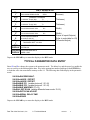
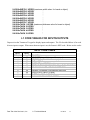
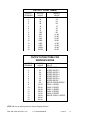
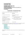
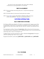
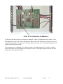
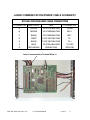
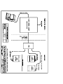
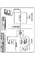
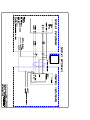
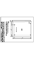
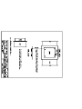
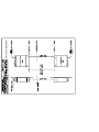
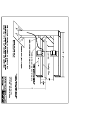
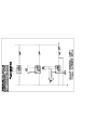
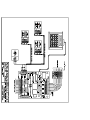
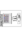
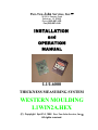
Paw-Taw-John Services, Inc. 18125 N. Ramsey Road Rathdrum, ID 83858 Phone (208) 687-1478 Fax (208)-687-4148 INSTALLATION and OPERATION MANUAL L1/L6000 THICKNESS MEASURING SYSTEM WESTERN MOULDING L1WIN2A.HEX (C) Copyright April 14, 1998 Paw-Taw-John Services, Inc. All rights reserved. L1/L6000 LASER THICKNESS GAUGE SYSTEM TABLE OF CONTENTS INTRODUCTION 1 SYSTEM COMPONENTS L1 Interface Board L6000 Laser Thickness Gauge 1 1 2 INSTALLATION INSTRUCTIONS Control/Interface Enclosure L6000 - Top Scanning Differential (Top & Bottom) Scanning 2 2 3 4 APPLYING POWER 6 TYPICAL SYSTEM PROGRAM SETUP TransTerm 5 (TT5 Keyboard) Set up TransTerm 5 Register Check TransTerm 5 Terminal Displays Typical Parameter Data Entry Parameter Definitions Window Mode Parameters L1 Code Table for Inputs/Outputs Output Structure for Windows Mode TransTerm5 Troubleshooting 7 7 8 9 10 11 12 13 14 15 L6000 LASER ALIGNMENT Top Scanning Laser Alignment Differential Scanning Laser Alignment Width Alignment 16 16 16 17 SYSTEM OPERATION NAC Computer Systems PLC Systems Laser Communication/Power Cable Schematic 17 17 18 19 PRODUCT WARRANTY 20 SALE AGREEMENT TERMS AND CONDITIONS 22 SERVICE AGREEMENT 24 DRAWINGS INTRODUCTION The Laser Thickness Gauge System developed by Paw Taw John Services, Inc. is a thickness and width measuring system that utilizes the L1 interface board and the L6000 laser thickness gauge. It offers users the flexibility of interfacing to PLC based systems, PC based systems or stand-alone systems and it is easily installed in most environments. Top scanning of product thickness is more commonly used, but bottom scanning is also possible. Although the system can be used in many industrial applications, the wood products industry is currently the primary user. Measurement of board thickness and width is used with board sorter and trimmer systems and in particle board, waferwood and veneer plants. Another application could be interfacing to quality control information systems. COMPONENTS OF THE SYSTEM L1 INTERFACE BOARD The L1 interface board is designed to adapt to many thickness and width measurement applications. The board uses a high-speed microcontroller for data processing. Twelve source inputs and sixteen source outputs make up the I/O structure of the board. Hooking up to host systems is facilitated by screw-in terminal strips. Inputs 9 through 12 are dedicated to special functions, the optically isolated inputs and outputs are rated for 5vdc to 32vdc and all I/O points have LED indicators for determining their status. The board is capable of interfacing to Quadrature or single input encoders. Encoder interfacing can be accomplished with either source or sink type outputs. Frequencies are limited to 1.5k Hertz with single input encoders, while Quadrature encoder frequencies are unlimited. Two communication ports provide RS-485 or RS-422 serial interfacing. The RS-485 port is dedicated to the L6000 laser thickness gauge, while the RS-422 port can be used for a dummy terminal and/or digital display. Connections to the RS-422 port are made with a phone jack. The RS-485 connections are made to screw-in terminal strips. Baud rates are determined in the operating program and must be specified by the user. Power is applied through the screw-in terminal strips. The board uses 5VDC and 24VDC, and a DC to DC converter can be used to generate 5VDC for the circuitry on the board. The input range is 18-72VDC and there are LED indicators to provide the status of the power, laser and RS-485 receive/transmit lines. L6000 LASER THICKNESS GAUGE The Model L6000 is a non-contact measurement device used in conjunction with the L1 interface board. The unit consists of a three-piece aluminum case with the following components mounted inside: a manufactured laser assembly; a video detection device; and a circuit board for computerized data collection and laser control. A beam emission indicator and power/data connector are mounted on top of the unit for easy access and visibility. An addressing port is also located on top of the unit under a screw-in plug, facilitating setup. Paw-Taw-John Services, Inc. L1 Technical Manual 02/20/03 1 INSTALLATION INSTRUCTIONS The instructions in this section cover installation of the following: the Control/ Interface Enclosure, which contains the L1 interface card; the L6000 Laser Thickness Gauge when the application is top scanning only; and the L6000 when the application is differential (top and bottom) scanning. At this point, you may wish to look at Drawings 1-4 in the Drawings section at the end of this manual. These show typical system layouts. CONTROL/INTERFACE ENCLOSURE The Control/Interface Enclosure can be mounted near the location of the L6000 or in a computer room. It is important to consider the environment of the mounting area. For example, is there severe vibration, is dirt and foreign matter excessive, and/or is access difficult? The enclosure can withstand these problems to a point, but it’s essential to use common sense about the location. OBSERVE ALL WARNING SIGNS AND INDICATORS OBSERVE ALL LOCAL LOCKOUT PROCEDURES BEFORE INSTALLING EQUIPMENT After the enclosure is mounted, follow the next 3 steps. STEP 1. Hook up 115VAC cable to the terminal blocks in the enclosure. Refer to Drawing 5 for power distribution. STEP 2. Hook up I/O connections to the L1 board per Drawing 6. STEP 3. Hook up the L6000 laser gauge power/communications cable to the L1 board per Drawing 6. L6000 - TOP SCANNING CAUTION USE OF CONTROLS OR ADJUSTMENTS OR PERFORMANCE OF PROCEDURES OTHER THAN THOSE SPECIFIED HEREIN MAY RESULT IN HAZARDOUS RADIATION EXPOSURE Refer to Drawings 7 and 8 in the Drawings section of this manual when mounting the L6000 Thickness Gauge. Since the communications to the laser head are provided by RS-485, it is possible to have cable Paw-Taw-John Services, Inc. L1 Technical Manual 02/20/03 2 runs in excess of 100 feet. If this option is used, however, the laser power supply should be moved to the location of the laser head. This prevents any power loss due to the length of the cable. The communications/power cable to the gauge can be put in ¾” conduit or strapped to the frame mounting. The cable is tough but carefully consider the environment before using the latter method. You will need bolts and washers for mounting. We suggest using 3/8” steel plate with ¼” holes drilled to the hole pattern shown in Drawing 7. Weld the plate to the framework above the measuring area and the bolt laser gauge to it. The distance to the measuring area should be per Drawing 8. It is important for accuracy that the laser be squared with the measuring area. If a hold down shoe is used, mount the gauge close to it. The shoe or any other mechanical object must be completely clear of the measuring area or window. This prevents any erroneous measurements from occurring. Mount the laser gauge near and above a solid base where the measurements will be referenced. For example, mounting near a lug chain raceway is good. This prevents any flexing of the product being measured and provides an accurate reading. If this mounting is used, it is advisable to use a nickel-plated skid bar near the lug chain raceway. This allows the product to be carried through the scan area with a stable reference point. Lug chains can cause errors in thickness readings due to wear of the chain, raceway and lugs. This method counters that problem. Other mounting scenarios are possible. Contact Paw-Taw-John Services, Inc. at (208) 687-1478 if there are questions about mounting. DIFFERENTIAL (TOP & BOTTOM) SCANNING Installation of the system for differential scanning involves the same concerns about the environment as top only scanning. However, the L6000 thickness gauges are mounted differently and are more critically placed in relationship to the zero reference area. Also, the bottom scanner needs to have an air exhaust system to keep the lens window and laser port free of debris. This prevents foreign material from blocking the laser gauge’s sensor and emitter. Refer to Drawings 9 and 10 for specifics about the installation of the top and bottom scanners. After the gauges are mounted, remove the plugs at the top or bottom of the units and verify that the address DIP switches are per the system requirements. Use the Address Port View picture and table below. Reinstall plugs. ADDRESS PORT VIEW Paw-Taw-John Services, Inc. L1 Technical Manual 02/20/03 3 LASER ADDRESS PROGRAMMING L600 NUMBER 1 2 3 4 5 6 7 1 OFF OFF OFF OFF OFF OFF OFF 2 ON OFF ON OFF ON OFF ON 3 OFF ON ON OFF OFF ON ON Switch Position 4 5 OFF ON OFF ON OFF ON OFF ON OFF ON OFF ON OFF ON 6 OFF OFF OFF OFF OFF OFF OFF 7 OFF OFF OFF OFF OFF OFF OFF 8 OFF OFF OFF OFF OFF OFF OFF On the L6000, move the laser mechanical aperture cover to uncover the laser beam. See the Disc View picture below. DISC VIEW Paw-Taw-John Services, Inc. L1 Technical Manual 02/20/03 4 CAUTION Verify that power, laser power and circuit breaker are turned off in the enclosure. Before applying power insure that all warnings related to the L6000 thickness gauge is observed. APPLYING POWER This section applies to both top-scanning only and differential systems. Hook up the power/communication cables to the L6000 and follow the steps below to apply power and prepare the system for operation. 1. 2. 3. 4. 5. Verify that AC is present at the circuit breaker. Turn on the breaker. Turn on the POWER switch and verify that the L1 board power LED comes on. If a terminal enable switch is used, switch to Terminal Enable on the front of the enclosure. Turn on the Laser Power switch. TransTerm 5 (see next section regarding TransTerm 5 setup) will beep and display SYSTEM OKAY on the second line. 6. After about 4 seconds, the laser emission indicator on top of the L6000 will come on. 7. Using only one L6000, LED A will be on. Using two (top and bottom scanning), LEDS A and B will be on. VIEW OF LEDS 8. TX and RX LEDS will be on, dimmed, or blinking. 9. Use a DVM to measure the following voltages on the L1 terminal strip. Paw-Taw-John Services, Inc. L1 Technical Manual 02/20/03 5 L1 Voltages Terminals From +5VDC "+12VDC "-12VDC +24VDC* Voltage To Minimum Maximum GND +4.9VDC +5.2VDC GND +12.1VDC +13.0VDC GND -12.1VDC -15.2VDC 24V RET* +5VDC +30VDC * Input/Output Supply Voltage TYPICAL SYSTEM PROGRAM SETUP TransTerm 5 Terminal Setup The TransTerm 5 is a complete terminal capable of all functions encountered on a normal personal computer system. The unit can be powered using a 12 volt external power unit or power can be applied to the D-25 connector. Connect the keypad cable to the TransTerm 5 and plug the opposite end of the cable into the RJ-style jack on the face of the L1 interface card. Refer to Drawing 11 for wiring information. When power is applied the TransTerm 5 should beep three times. The top line will display the L1 firmware program name and date. The bottom line will initialize for a moment and then display a card status message. PRGMNAME 1/15/95 MASTER SYSTEM OK means the L1 and the scanners are communicating and working. If the SYSTEM OK message is not displayed, you may see one of the following: Scanner 1 Bad means scanner 1 is not working. Scanner 2 Bad means scanner 2 not working. This would mean the scanner needs to be replaced. Trans-Term 5 Register Check Paw-Taw-John Services, Inc. L1 Technical Manual 02/20/03 6 A TransTerm 5 register check should be conducted next to make sure the TT5 is set to properly communicate with the L1 card. It is necessary to switch to the setup mode by entering the following keystrokes: S2 (blue key), S1 (red key) and S2 (blue key). The top line shows SR indicating the setup register mode and two sequential counts from 1 to 8 to mark data bit positions. The bottom line of the display shows which of the four registers (SR1 - SR4) is active, the data for that register and the blinking cursor at the first new data entry position. Each register contains 8 data bits that are either “1” or “0”. This data determines how the TT5 will work. It is necessary to have the registers filled with the exact sequence of “1”s and “0”s so the terminal can communicate with the L1 interface board. Card. The bit sequence for register SR1 should be as follows: SR1=0000000 If the data displayed does not match, key in “00000000”. Then press the ENTER key. If the data displayed does match the bit sequence, just press the ENTER key to accept the data as displayed. After the ENTER key is pressed, the display will automatically change to the next register. Repeat the procedure for all four registers, confirming or changing the data bits to match the following: SR2=00000010 SR3=00001001 SR4=00000000 Hit the ENTER key after each register entry. When all four registers are correct press the CLEAR key to exit the setup mode. NOTE: Please refer to TransTerm 5 Troubleshooting page at the end of this section if no data is displayed. Also refer to the TransTerm 5 User’s Manual (included with the system) for more detail on terminal setup. Paw-Taw-John Services, Inc. L1 Technical Manual 02/20/03 7 TransTerm 5 Terminal Displays The TransTerm 5 is a basic data entry terminal used with the L1 board. The Transterm 5 incorporates all key functions available on a standard keyboard. The specific key functions used with the L1 system are as follows: L1 COMMANDS Command Sequence CLEAR ENTER SPACE DELETE S1 Î P S1 Î A S2 Î B 1 2 3 4 5 6 7 Function or Action Return system to Run mode Enter values previously typed in Scroll forward to next entry Scroll backward to previous entry Enter Parameter Mode Enter Windowed Size Value Table Enter Windowed Size Value Table View Raw Scan data with Offset Value included View Average Thickness View Largest Thickness Out View Width Count View Largest Width Out View I/O data for L1 inputs and outputs View Differential Scanned value Different systems will utilize different combinations of these commands. Paw-Taw-John Services, Inc. L1 Technical Manual 02/20/03 8 KEY DISPLAYS Key RAW SCAN WITH OFFSET SCN1=00.000 SCN2=00.000 SCN= 1 Key AVERAGE THICKNESS T1=XX.XXX T2=XX.XXX T= 2 Key LARGEST THICKNESS OUT T1=XX.XXX T2=XX.XXX T= 3 Key WIDTH COUNTERS W1=XX.XXX W2=XX.XXX W= 4 Key LARGEST WIDTH OUT W1=XX.XXX W2=XX.XXX W= 5 Key I/O FOR MASTER BOARD IN=XX OUT=XX XX 6 Key SCAN1+SCAN2-DIFF_ADJ DIFF= THICKNESS DIFF.=XX.XXX 7 RUN PROGRAM NAME/DATE DISPLAY SYSTEM OK TROUBLE PROGRAM NAME/DATE DISPLAY LASER 1 BAD (Scanner) (Thickness) (Thickness) (Width) (Width) (Status of Inputs/Outputs) (Refer to code table for I/O) (Differential Adjust) Depress the CLEAR key to return the display to the RUN mode. TYPICAL PARAMETER DATA ENTRY Enter S2 and P to change the system to the parameter mode. The delete key and the space key enable the user to scroll up or down through the data. Key in the appropriate number and depress the ENTER key to load that value into nonvolatile memory on the L1. The following data fields display in the parameter mode: XX.XXX=ENCODER MULT. XX.XXX=LASER 1 OFFSET XX.XXX=LASER 2 OFFSET XX=ENABLE PC1 (enable photo cell 1 IF=12) XX=ENABLE PC2 (enable photo cell 1 IF=12) XX=ENABLE WINDOWS (IF=12) XX=ENA. DIFF.SCAN (enable differential scan mode IF=12) XX.XXX=DIFF.SCAN ADJUST XX.XXX=SERIAL DELAY TIME XX.XXX=SPARE Depress the CLEAR key to return the display to the RUN mode. Paw-Taw-John Services, Inc. L1 Technical Manual 02/20/03 9 PARAMETER DEFINITIONS ENCODER MULT(IPLER) The number (to thousandths) that the encoder pulse is multiplied by to develop width information. LASER 1 OFFSET Used to calibrate Laser 1 reading to a known thickness value. For example, if a known thickness of 2" is placed in the range of the L6000, this value can be adjusted to reflect that known value. LASER 2 OFFSET Used to calibrate Laser 2 reading to a known thickness value. For example, if a known thickness of 2" is placed in the range of the L6000, this value can be adjusted to reflect that known value. ENABLE PC1 This value is 12 if a photo cell is used to determine when a board is in the scanner one window. Any other value disables this feature. ENABLE PC2 This value is 12 if a photocell is used to determine when a board is in the scanner 2 window. Any other value disables this feature. ENA.(BLE) DIFF.(ERENTIAL) SCAN This value is 12 if the user wants discrete outputs for different ranges of width and thickness values. The windows table (accessed by depressing S1, A) must have values entered for this function to operate. DIFF.(ERENTIAL) SCAN ADJUST This data entry point is used to calibrate thickness readings when two L6000 thickness gauges are reading a thickness in opposing direction - for example, when using top and bottom scanning. SERIAL DELAY TIME This value controls the time when thickness and width serial information is transmitted out of the RJ-style jack on the side of the L1 board. On some serial display devices, a flickering will occur if the data is too fast and overfills the communications buffer. This feature corrects that problem. The communications baud rate is 9600. WINDOW MODE PARAMETERS Depress S1 and A to enable the WINDOW parameters. Enter board thickness and width values here for discrete outputs on the L1 board. Again, depress the DELETE and SPACE keys to scroll through the screens. The ENTER key loads the entered values. When this parameter mode is enabled, the following screens will be displayed: WINDOW SELECT Paw-Taw-John Services, Inc. L1 Technical Manual 02/20/03 10 X.XXXX=WIDTH 1 UPPER (maximum width value for board or object) XX.XXX=WIDTH 2 UPPER “ XX.XXX=WIDTH 3 UPPER “ XX.XXX=WIDTH 4 UPPER “ XX.XXX=WIDTH 5 UPPER “ XX.XXX=WIDTH 6 UPPER “ XX.XXX=WIDTH 7 UPPER “ XX.XXX=THICK 1 UPPER (maximum thickness value for board or object) XX.XXX=THICK 2 UPPER “ XX.XXX=THICK 3 UPPER “ XX.XXX=THICK 4 UPPER “ XX.XXX=THICK 5 UPPER “ L1 CODE TABLES FOR INPUTS/OUTPUTS Depress 6 on the Transterm 5 keypad to display inputs and outputs. The I/O described below is for each discrete input or output. When more than one input is on, the format is HEX code. Below are the codes: INPUT CODE TABLE INPUT TERMINAL 1 1 2 3 4 5 6 7 8 9 INPUT VALUE 00 01 02 04 08 10 20 40 80 Paw-Taw-John Services, Inc. FUNCTION INPUT OFF (largest thickness will be output) INPUT ON (largest width wil be output) DATA HOLD PHOTO CELL 1 INPUT (if used) TEST INPUT FOR SENDING RAW SCAN DATA TO PC/PLC DISABLE SCANNER 1 READING/OPERATION DISABLE SCANNER 2 READING/OPERATION PHOTO CELL 2 INPUT (if used) EXTERNAL DISPLAY ENABLE SINGLE INPUT SOURCE ENCODER L1 Technical Manual 02/20/03 11 OUTPUT CODE TABLE OUTPUT TERMINAL 1 2 3 4 5 6 7 8 9 10 11 12 13 14 15 16 OUTPUT VALUE 01 02 04 08 16 32 64 128 256 512 1024 2048 4096 8192 16384 32768 BINARY VALUE 01 02 04 08 10 20 40 80 01 00 02 00 04 00 08 00 10 00 20 00 40 00 80 00 OUTPUT STRUCTURE FOR WINDOWS MODE OUTPUT TERMINAL 1 2 3 4 5 6 7 8 9 10 11 12 13 14 15 16 BINARY VALUE 01 02 04 08 10 20 40 80 01 00 02 00 04 00 08 00 10 00 20 00 40 00 80 00 VALUE UPPER WIDTH 1 UPPER WIDTH 2 UPPER WIDTH 3 UPPER WIDTH 4 UPPER WIDTH 5 UPPER WIDTH 6 UPPER WIDTH 7 ABOVE UPPER WIDTH 7 THICK 1 UPPER THICK 2 UPPER THICK 3 UPPER THICK 4 UPPER THICK 5 UPPER ABOVE THICK 5 UPPER STEP 10. Set up initial parameter data as displayed below. Paw-Taw-John Services, Inc. L1 Technical Manual 02/20/03 12 XX.XXX=ENCODER MULT. XX.XXX=LASER 1 OFFSET XX.XXX=LASER 2 OFFSET XX=ENABLE PC1(PHOTO CELL 1) IF=12 XX=ENABLE PC2(PHOTO CELL 2) IF=12 XX=ENABLE WINDOWS IF=12 XX=ENA. DIFF.SCAN(ENABLE DIFFERENTIAL SCAN MODE) IF=12 XX.XXX=DIFF.SCAN ADJUST) XX.XXX=SERIAL DELAY TIME XX.XXX=SPARE TRANSTERM 5 TROUBLESHOOTING Listed below are troubles that are sometimes encountered and solutions. TROUBLE SOLUTIONS Unit displays erroneous characters. Check the terminal for proper configuration. Unit displays cursor in upper left corner of display only. Check the connections between the terminal and the L1 interface board. With power applied, the terminal doesn't display a cursor or characters or doesn't beep three times when powering up. The terminal is I/O bounded. Try another L1 board or replace the terminal. Unit displays SCANNER BAD. Replace scanner. To check the terminal for proper configuration, depress S2, S1, S2. (Refer to TransTerm 5, operators manual, Chapter 6, page 11, TransTerm 5 set-up). The shift registers are as follows: SR1=00000000 SR2=00000010 SR3=00001001 SR4=00000000 OPERATING MODE=001 CONTRAST=007 UNIT ADDRESS=001 TOTAL COLUMNS=024 The DB25P cable is wired per table. Check connector for broken wires or other damage and repair as necessary. Paw-Taw-John Services, Inc. L1 Technical Manual 02/20/03 13 TRANSTERM 5 CABLE WIRING Signal DTD+ DTDDRD+ DRDGRD +12VDC DRO DTR Pin # 23 22 25 24 7 20 16 to 3 20 to 5 Color green red black yellow blue white jump to RD jump to CTS L6000 LASER ALIGNMENT TOP SCANNING LASER ALIGNMENT STEP 1. Depress 1 on the TransTerm 5 keypad. SCN1 XX.XXX SCN2 XX.XXX are displayed. STEP 2. Put an object or piece of wood with a known value of thickness underneath LASER 1 measuring area. a. A thickness reading of the object being measured appears on the display. b. Record the SCN reading for the head. STEP 3. Depress S2, P. Using the TRANSTERM 5 TERMINAL DISPLAYS section of this manual, scroll to LASER 1 OFFSET. a a. Enter an offset value to make the SCN recorded value equal to the object measured. This will require going back and forth between displays to setup. Once the SCN value equals the object value, the laser head is calibrated. b. If more lasers are used, repeat STEPS 1-3 for each head. DIFFERENTIAL SCANNING LASER ALIGNMENT STEP 1. Depress 7 on the TransTerm 5 keypad. The following is displayed: SCAN1+SCAN2-DIFF_ADJ DIFF=(DIFFERENTIAL ADJUST) THICKNESS DIFF.=XX.XXX STEP 2. Put an object or piece of wood with a known value of thickness between LASER 1 and LASER 2 measuring area. a. A thickness reading appears on the display. b. Record the THICKNESS DIFF.=XX.XXX reading for the heads. STEP 3. Depress S2, P. Using the TRANSTERM 5 TERMINAL DISPLAYS section, scroll to XX.XXX=DIFF.SCAN ADJUST). a. Enter an offset value to make the THICKNESS DIFF. recorded value equal to the object measured. This will require going back and forth between displays to setup. Paw-Taw-John Services, Inc. L1 Technical Manual 02/20/03 14 Once the SCN value equals the object value, the laser head is calibrated. b. If more lasers are used, repeat STEPS 1-3 for each head. WIDTH ALIGNMENT STEP 1. Measure the distance between lugs and record. Verify the encoder pulses per revolution. STEP 2. Divide the distance by the amount of encoder pulses per revolution. STEP 3. Depress S2, P. Using the TRANSTERM 5 TERMINAL DISPLAYS section, scroll to ENCODER MULT. Enter the value determined in STEP 2. SYSTEM OPERATION NAC COMPUTER SYSTEMS The Thickness/Width system, Model No. PTJ L6001A, is used with the NAC computer system. Thickness information is sent to the NAC by a transmit pair via the phone jack on the L1 interface board. A switch on the front of the enclosure enables either the TransTerm 5 terminal or the transmit pair to the NAC. The string format is as follows: T xx.xxx Carriage Return. When an object leaves the measurement zone, the thickness data is transmitted to the NAC. Although the outputs of the L1 are not used, the LEDs should change status as objects flow through the zone. If width measuring is used, the string format is as follows: W xx.xxx Carriage Return. This output is enabled by inputting a high to input 1 of the L1 board. Programs used with NAC systems are L1_NAC2C.HEX, L1_NAC3A.HEX and L1_NAC3B.HEX. PLC SYSTEMS Paw-Taw-John Services, Inc. L1 Technical Manual 02/20/03 15 HOST PLC INTERFACE TERMINALS To the left of the above figure, are sixteen wire terminals. These are outputs that can be used by a PLC. Depending on the logic state to the width/thickness input on the card, determine what binary word is present at this terminal strip. Using the L1 code table shown earlier, the user can determine the thickness or width of an object in binary code. These outputs can be configured for a windowed output. By programming the L1 card for a windows output, the output section will light only one output at a time. These single outputs reflect an item that has passed a user programmed table. Paw-Taw-John Services, Inc. L1 Technical Manual 02/20/03 16 LASER COMMUNICATION/POWER CABLE SCHEMATIC M13146 6 PAIR SHIELDED CABLE CONNECTIONS J1 CONNECTOR WIRE COLOR PAIR L1 CONNECTOR A YELLOW 1/2 OF YEL-BLK PAIR "+12VDC B BROWN 1/2 OF BRN-BLK PAIR REC + C BLACK 1/2 OF BRN-BLK PAIR REC - D WHITE 1/2 OF WHT-BLK PAIR TX - E BLACK 1/2 OF WHT-BLK PAIR TX + F BLUE 1/2 OF BLU-BLK PAIR "-12 VDC G RED AND BLK RED-BLK PAIR GRD/COM Laser Communication Terminal Strip J1 Paw-Taw-John Services, Inc. L1 Technical Manual 02/20/03 17