1
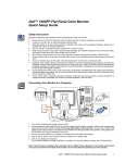
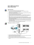
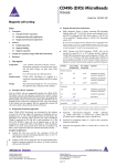
1. General Information
JS series high-accuracy ultrasonic welder is mainly used for secondary joining of
thermoplastics. Compared with other traditional processes (such as gluing, electric
heat-joining, or screw tightening), it has remarkable advantages like high productivity,
sound welding quality, environmental protection and energy saving, among others.
2. Structural characteristics and Working principle
JS series high-accuracy ultrasonic welder converts the electric energy into
ultrasonic energy through the ultrasonic transducer (i.e. high-frequency mechanical
vibration energy with the frequency exceeding the threshold of human’s auditory
sense). Conducted to the plastic work piece through the welding head, such ultrasonic
energy melts down the joint face of the plastic work piece after rubbing the joint face
violently with ultrasonic frequency at the speed of tens of thousands of times per
second and with certain amplitude. The transient pressure maintained at the work
piece after stopping vibration makes two pieces of weldment solidify together in the
form of molecular interlinkage. Generally, the welding time is less than 1 second, but
the weld strength compares favorably with that of a weldment itself.
By adopting electronic program control, JS series high-accuracy ultrasonic
welder has such features as high automation, built-in full automatic protective circuit,
easy and safe operation, stable and reliable running, etc.
JS series high-accuracy ultrasonic welder is applicable for butt welding of
thermoplastics. With its welding head replaceable according to the customers’
requirements, the welder can also be used for processing such as rivet welding, spot
welding, embedding, cutting, etc.
External view and all parts introduction, as follows:
pressure detection
LCD
operating keyboard
Fall speed regulating
Rising speed regulating
air pressure governor
Acoustic welding head
positioning tooling
Double-start button
jerk button
Frequency deviation gauge
Frequency control
fuse-holder
Power cord
load gauge
earth terminal
Power indication
Frequency deviation indication
Power switch
Ultrasonic testing
logic line plug
ultrasonic line plug
Main Technical Parameters
1. Operating voltage: monophase AC220V±%5
2. Apparent power of transducer:
□1500W □2000W □2600W
3. Ultrasonic frequency: □15KHz
□4200W
□20KHz
4. Power supply noise: no more than 100Vp_p
5. Momentary interruption permission: less than 10ms
6.
Working temperature: 0~50℃
7. Equipment Storage Temperature: -10~60℃
8. Environment humidity: 20~70% (no condensation)
9. No source of vibration environment.
10. Dust-free, non-corrosive gases environment
3. Equipment Installation
z
The equipment should be installed on the solid table board, with a space
of 150mm in the rear.
z
Since the welder has relatively higher requirements for power supply,
unstable voltage will exert direct influence on the welding effect, or in an
even more serious case, result in shortening service life of power
generator or burning it! Areas with unstable voltage require a voltage
stabilizer with fluctuation of output voltage below 2% and the output
power double the nominal power of the welder.
z
There should be no fire source around, and well-ventilated, and the
installation should be smooth.
z
Before operating the welder, make sure to connect the ground wire
properly, with ground resistance less than 0.5ohm.
Never operate the welder without proper grounding!
z
Before switching on, please make sure that proper power supply and air
supply are used, the cable wires have been connected correctly, the
limit of welding head has been well set, and the hands and other parts
are at safe operation position
4. Application Notice
1)
User shall not alter welding head at option, or it may change
frequency
parameters of transducer system, which will result in
damages to transducer system and ultrasonic power generating
system.
2)
Never leave both hands under the welding head when the machine
is in operation or is testing ultrasonic sound, to guarantee operating
safety for operators!
3)
No direct contact is allowed between the welding head and the
machine base or other metal fixtures during operation or test, to
ensure safe operation of the equipment;
4)
No start-up or operation of this equipment is allowed before reliable
connection to earth!
5)
Start-up or operation is prohibited where high temperature and high
dust environment exist!
6)
Stable operational power supply is required while operation beyond
the rated voltage is prohibited!
7)
Earplugs are recommended for a long-term operator to avoid injury
by noise pollution;
8)
Proper ventilation facilities should be made available when
processing noxious plastic parts or those with peculiar smell,
9)
Stop and check the machine immediately in case any abnormal
noise occurs or transducer system heats to over 50℃ during
operation. Only after returning to normal can the production be
continued; If temperature of transducer system is still on the high
side, continuous operation shall only be allowed after cooling it
down. In special situation, forced heat-elimination measures should
be taken.
10)
If fuse of the machine is blown, a fuse with regulated nominal
value should be adopted. If fuse is blown for several times, the
machine should be stopped immediately for inspection. Only after
an error (errors) is located and proper repairing is conducted can it
be put into application;
11)
Ensure a clean air supply. When air filter is half full of water,
immediate discharging should be made.
12)
Lubricate mechanical movable parts at regular intervals; remove
dust from electric cabinet regularly after a long time operation; if
equipment is not used, proper dust cover should be chosen to cover
them;
13)
If heat emission fan gets blocked from running, stop immediately
for inspection. Continuous use will not be allowed until normal
condition is resumed;
14)
Special staffs shall be designed for debugging and maintaining
the equipment;
15)
Please feel free to contact us should any error occurs. No
continuous use or optional alteration is allowed. Press the
operational button with both hands for operation. Foot operated
switch is not available for this machine. Any consequences resulting
from self-modification or self-setting shall not be our responsibility.
5. Equipment Operating Instructions
1) Ultrasonic generator instrument
¾ Load gauge: used for the actual load current direction of generator,
also used as output power instructions. When the load sheet indicates a
large number, the generator automatically cuts off the power output, and
frequency deviation indicator lights.
¾ Frequency deviation gauge: the deviation of natural frequency of
transducer and woking frequency of generator. When frequency deviation
gauge indicates a large number, the generator automatically cuts off the
power output, and frequency deviation indicator lights.
¾ Frequency adjustment knob: used to adjust the frequency of
generator.
¾ Ultrasonic testing button: jog the button for testing whether
ultrasound and generator are normal. Commonly used for equipment
debugging.
¾ Deviation indicator: when the deviation of natural frequency of
transducer and working frequency of generator is too large or the load
current exceed the maximum limit current, the generator automatically
cuts off the power output, and indicator lights.
¾ Power switch: the main power control.
¾ Earth terminal: earth resistance should be less than 0.5 ohms.
¾ Signal output: 4-pin airline outlet.
¾ Logic signal Input: 7-pin airline outlet.
2) Ultrasonic generator ajustment
Confirm that the logic signal line and ultrasonic wire are connected
normally. Turn on the power, jog "ultrasonic testing", if the deviation
indicator light, please adjust "frequency control" knob and jog "ultrasonic
testing" button until the deviation indicator does not light. At this time,
continue to fine-tune "frequency control" button until the deviation gauge
pointers indicate the minimum, if continue to increase or reduce the
"frequency control" button, the deviation gauge pointers will indicate a
large number again.
Attention:
1.When regulating, jog the "ultrasonic testing"″ button, do not continue to press.
2.Ultrasonic generator is well ajusted when: deviation gauge points the minimum
(usually within three cells), in no-load (no pressure) state, the load gauge points within
two cells. If the load gauge points a large number, please contact the manufacturer.
3.The less in the potential difference between natural frequency of transducer and
working frequency of generator, the better.
3)
z
LCD display normal working information
Operating mode
The operating modes of this control system are shown as follows in Figure 1.
Turned on the power normally, press [OK] button to enter the following screen.
Operating modes:position mode
Time mode
system debug
Run Count:100
Figure 1 The main interface
As shown, the control system has three kinds of operating modes.When powered,
the system default is the last working mode, the default mode of operation highlights,
such as the time mode above.
Working mode selection method:
After power-on, press the [∧] or [∨], select one of the three operating modes, the
highlighted one is the selected mode.
z
Position model working process
This model is the application mode of other types, so omitted.
z Time mode working process
When choosing time mode, just as shown in figure 1 that time mode in
operating model highlights. In the reset of [STOP] button, press the [Start]
button, into the working process of time model, as follows:
StartÆ release weld headÆdelay time to the [can be set] Ærelease
ultrasoundÆ release time to [can be set] ÆcoolingÆpressure holding
time to [can be set] Ærun count value plus 1Æweld head ascendÆtime
interval to [can be set] Æ'tick' signals the end
Attention: In working process, if press [STOP], ultrasonic output will be cut off,
and weld head auto ascend to the pointed time, 'tick' indicate, but run count does
not count.
z
System debug mode working process
When choosing system debug mode, just as shown in figure 1 that system debug
mode highlights.
Working process is shown as follows:
In system debug mode, press [OK] to enter the Figure 2 screen.
Press[∧], welding head ascends, action self-locking.
Press[∨], welding head descends, action self-locking.
Press [Test], release ultrasound, action is not self-locking.
System debugk
Welding head ascend &descend
Ultrasonic testing-ultrasonic releasing
Cancel-return to
Figure 2
system debug screen
Press [Return], debug end, return to the main screen. Welding head ascend to
pointed place, buzzer sounds. Or show no operation in 120S, automatically return to
the main screen.
z Parameter setting
Parameter setting mainly means various time parameters, as following in Figure 3.
Meanings of parameters set :
- Delay time: refers to in time mode, the time from welding head start descend to the
release of ultrasund.
- Welding time: refers to the time of releasing ultrasound.
- Pressure holding time: refers to the time of welding workpiece-cooling after releasing
ultrasound.
- Interval time: refers to the interval of permitting next welding after cooling.
Delay time 2.01s
Welding time 1.70s
Pressure holding time
Interval time 1.00s
0.92s
Figure 3 parameter setting screen
Achieving method is as follows:
In time mode or position mode, press [OK] to enter the parameter setting screen
shown in Figure 3. The default screen shows delay time parameters. Delay time font
highlights.
By choosing [∧] or [∨] to select delay time, welding time or pressure holding time.
- Press [OK] to enter the parameter values to be set.
- Click [∧] or [∨] to add or subtract the selected parameter value. Parameter value
range : 0-19.99S.
- Uninterruptable press[∧] or [∨]to add or subtract parameter value by interval of 0.1s.
- Uninterruptable click [∧] and [∨]to add or subtract parameter value by interval of
0.01s.
- Click [OK] to return to parameter setting screen.
- Click [Back] to return to the main screen.
Notice: Others
1.The system enter non-work screen, if there is no continuous operation, then it will
automatically return to working screen after 120s.
2.Wiring attention, best to separate the input and output wiring bundle.
3. Automatically memorize the last working model after each power-on.
4.Run count reset: In the working screen, press [Return], this count clears.
1.
Pressure Sensor Setting
Display screen
OUT 1 light
OUT 2 light
up & down
button
set
Press [set], in the display screen will switch to display P-1, P-2, P-3, P-4. In them,
P-1, P-2 is pressure detection range value of out 1. P-3, P-4 is pressure detection
range value of out 2. This machine uses only one output (output 1), so only setting
P-1 the lowest pressure detection range value, and setting P-2 the highest
pressure detection range value. Press [set] , switch to P-1, press up and down
button to change set value. Change P-2 in the same way.
z Speed Control Valve
Increase in speed regulation of and decrease speed adjustment is used to adjust
the cylinder lifting speed, the actual work needed to be adjusted depending on
the speed.
6.
Troubleshooting for Frequently Asked Questions and
Equipment Maintenance
1. When turning on power switch, power indicator doesn’t light and fan
doesn’t run, and no response is seen to operation, then possible causes are as
follows:
a. No electricity for power source, please check to confirm;
b. Bad contact between power line and outlet, please make due
repairing;
c. If fuse of equipment power supply is blown, please change fuse with
regulated nominal value.
2. If non-logic action is found, please make inspection as suggested below.
Contact our service staff if it still can’t be solved.
a.
b.
c.
d.
Check if connection of logic cable conductor is normal;
If two operational buttons are well connected;
If air supply is normal;
If emergency stop is reset and any error exists;
3. In the event of unstable logic control, check and handle it as follows. If not
successful, please contact our service department in case of failure.
a. Caused by the interference due to too close distance between the
logic wire and the power output wire.
b. The logic wire or logic board is in contact with the ground wire, or too
close to the ground wire.
c. The connecting plug-in units of the logic wire are in bad contact.
d. Power supply is impure, with interference factors.
e. Supply voltage fluctuates greatly.
4. Unstable welding quality.
a.
Nonuniform shape, dimensions or material quality of the weldment;
improper design of fusion face; improper selection of welder power and
amplitude of welding head.
b. Unstable supply voltage; unstable air pressure of air supply.
c. Occurrence of frequency deviation protection or overload protection
during welding.
d. Unstable outputting of ultrasonic.
e. Because the power output of this welder is adjusted automatically
according to the load, improper adjustment of the limit screw or the moving
stroke of the welding head exceeding allowable stroke of the welder may result
in the reduction of power output.
5. Occurrence of frequency deviation protection during welding.
a.
Improper adjustment of frequency. Raise the frequency slightly, to
surmount the influence of frequency rising on the transducer system under the
action of pressure. Ensure stable degree of frequency deviation with slight
changes during welding.
b. Parameters of the components of transducer system are matchless,
which is generally caused by too high natural frequency of the acoustic welding
head.
c. Serious heating up of the transducer system.
d. Too high welding pressure.
6. Unstable output of ultrasonic, and indication of high load but very faint
sense of ultrasonic vibration are mainly caused by the automatic tracking system
falling out of synchronism, with the following causes:
a. The working frequency deviates seriously, which causes the failure of
frequency tracking.
b. The transducer system is damaged seriously, or the parameters
deviate seriously.
c. Over high load while starting ultrasonic causes the failure of starting.
At this moment, shorten the delay time to bring the triggering mode under the
mode of advance triggering, or reduce the pressure to lower the starting load.
7. The following cases may be caused by the faults of the transducer system,
especially the acoustic welding head.
a.
High no-load current and unstable ultrasonic.
b. Particularly serious heating up of the welding head, and squealing of
the welding head while testing ultrasonic.
c. Constant frequency deviation protection or overload protection; invalid
frequency adjusting.
7. Special Statement
a) This manual is presented based on JS series high-accuracy
ultrasonic welder. Part of its framework may not comply with the model you
choose. Therefore, this manual is only for your reference, with your
concrete model subject to the real machine.
b)
Weihai Kaer Ultrasonic Engineering Co., Ltd reserves the right
for interpretation and revision for this manual. This manual is subject to
change without notice.