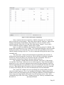
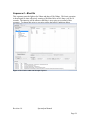
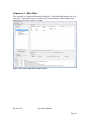
1
SpectraLynx User Manual LED based, millisecond time-scale, multicolor light-delivery system for Optogenetics Neuralynx, Inc. 105 Commercial Drive, Bozeman, MT 59715 Phone 406.585.4542 • Fax 866.585.1743 www.Neuralynx.com Revision 1.0 [email protected] Table of Contents 1 2 3 4 5 Document Revision History........................................................................................ 4 Document Overview ................................................................................................... 4 SpectraLynx Overview ............................................................................................... 4 Glossary ...................................................................................................................... 5 Components of the SpectraLynx Light Emitter .......................................................... 6 5.1 SMA cable/fiber output ........................................................................................ 8 5.2 Power Status LED ................................................................................................ 9 5.3 Power Switch........................................................................................................ 9 5.4 Power Connector .................................................................................................. 9 5.5 Connections on the Microcontroller Housing (Grey) ........................................ 10 5.5.1 Indicator 1 – USB Status............................................................................. 10 5.5.2 Indicator 2 – Board Status LED .................................................................. 10 5.5.3 Dip Switches ............................................................................................... 10 5.5.4 USB Connector ........................................................................................... 12 5.5.5 34 Pin TTL I/O Port .................................................................................... 12 5.6 Light Sensor Output (Monitor) .......................................................................... 13 6 Product Assembly and Use / Cabling Setups ............................................................ 14 6.1 Digital Lynx SX ................................................................................................. 14 6.2 Digital Lynx S .................................................................................................... 14 6.3 Neuralynx Analog Systems ................................................................................ 14 6.4 Other Data Acquisition Systems ........................................................................ 15 6.5 No System .......................................................................................................... 15 7 Pulse Software Installation and Use ......................................................................... 15 7.1 Software Installation .......................................................................................... 15 7.2 Main Menu ......................................................................................................... 15 7.2.1 File Menu .................................................................................................... 16 7.2.2 Connection Menu ........................................................................................ 16 7.2.3 Help Menu .................................................................................................. 17 7.3 Manual Control Tab ........................................................................................... 17 7.4 Sequence Control Tab ........................................................................................ 18 7.4.1 Initial Conditions ........................................................................................ 19 7.4.2 Sequence Setup (Commands) ..................................................................... 19 7.4.3 Sequence List Options ................................................................................ 22 7.4.4 Sequence Execution .................................................................................... 23 7.4.5 Message Log ............................................................................................... 23 8 Example Sequences .................................................................................................. 23 Sequence 0 – Blue1Hz .................................................................................................. 24 Sequence 1 – Blue 10Hz ............................................................................................... 25 8.1 Sequence 3 – Blue Intensity Change .................................................................. 26 8.2 Sequence 3 – Yellow10Hz ................................................................................. 27 8.3 Sequence 4 – BlueYellowAlternate ................................................................... 28 8.4 Sequence 5 – Switch from Yellow to Green ...................................................... 29 8.5 Sequence 6 – All On........................................................................................... 30 9 TTL I/O Based Controls ........................................................................................... 31 Revision 1.0 Spectralynx Manual Page 2 List of Figures and Tables Figure 5-1 The front panel of the SpectraLynx .................................................................. 6 Figure 5-2 The rear panel of the SpectraLynx .................................................................... 7 Figure 5-3 Detailed View of the SpectraLynx Control Inputs and Outputs ....................... 7 Figure 5-4 SMA adaptor on the front of the SpectraLynx .................................................. 8 Figure 5-5 Detailed View of the SpectraLynx Control Inputs and Outputs ....................... 9 Figure 5-6 View of the dip switches and two status lights. .............................................. 11 Figure 5-7 Detailed View of the SpectraLynx Control Inputs and Outputs. The pin numbering refers to the Yellow I/O pins on the left of the cartoon. The green ground pins are the even numbered pins............................................................................................... 13 Figure 5-8 Detailed View of the SpectraLynx Control Inputs and Outputs ..................... 14 Figure 7-1 Overview of the Manual Control Tab ............................................................. 16 Figure 7-2 Dialog for Setting the COM port and connecting to the SpectraLynx. Note that in this figure the software is connected to the SpectraLynx and the only option available is to disconnect. ................................................................................................................. 17 Figure 7-3 The Sequence Control Tab .............................................................................. 18 Figure 7-4 The initial conditions Dialog ........................................................................... 19 Figure 7-5 This is the Sequence Setup Dialog. ................................................................. 20 Figure 7-6 This is the Sequence Management Dialog. ..................................................... 22 Figure 7-7 The message log dialog. .................................................................................. 23 Figure 8-1 Screenshot of Blue 1Hz Example Sequence ................................................... 24 Figure 8-2 Screenshot of Blue 10Hz Example Sequence ................................................. 25 Figure 8-3 Screenshot of Blue Intensity Change Example Sequence............................... 26 Figure 8-4 Screenshot of Yellow 10Hz Example Sequence ............................................. 27 Figure 8-5 Screenshot of Blue Yellow Alternate Example Sequence .............................. 28 Figure 8-6 Screenshot of Switch from Yellow to Green Example Sequence ................... 29 Figure 8-7 Screenshot of All On Example Sequence ....................................................... 30 Figure 9-1 Detailed View of the Digital Lynx Control Inputs and Outputs. It is recommended that the lower port be used when connecting the SpectraLynx to the Digital Lynx SX since the Port numbers will then match up. The pinout for the SpectraLynx TTL I/O is show in Figure 5-7. Note that the port shown in 5-7 is upside down when compared to these ports. .................................................................................................................... 31 Table 5-1 Dip Switch Functionality Table........................................................................ 11 Table 5-2 Description of the TTL I/O ports on the SpectraLynx ..................................... 12 Table 9-1 Example of the use of the 7+1 TTL sequence activation command in Cheetah ........................................................................................................................................... 32 Revision 1.0 Spectralynx Manual Page 3 1 Document Revision History 8/3/2012 Rev 1.0 Initial Release 2 Document Overview This describes the specifications and features of the SpectraLynx system. It also explains how to setup your system, test it, and use it. There is a glossary at the end of the document. Throughout this document you will see this warning sign. An item or topic designated in a warning box is something that Neuralynx feels is important and should be carefully noted. 3 SpectraLynx Overview The SpectraLynx is a turnkey light delivery system for optogenetics. The hardware and software are designed to achieve millisecond time scale optical stimuli to brain tissue for use in optogenetics. The hardware includes a microprocessor controlled multicolor light engine (LED) and the cabling to connect to a data acquisition system if desired. The SpectraLynx can be utilized without a data acquisition system but its full potential as a turnkey integrated system is realized when it is paired with a Neuralynx Digital Lynx SX system. The light delivery portion of the SpectraLynx hardware comes in two standard configurations. The 2 color configuration has a blue (for Channel Rhodopsin 2 – ChR2) and yellow/orange (for Halorhodopsin – Halo). The 4 color unit adds two more colors green (for VChR2) and red (ChRimson or other red shifted variants). The main design principle behind the SpectraLynx is that it is a turnkey system. There are no lenses, light tables, control modules, or filters to buy. Just select the optical fiber of your choosing and terminate it with an SMA on the end that will interface with the SpectraLynx. Please note that different fibers and cables will produce different results depending on the configuration and properties of the optical fiber used. Revision 1.0 Spectralynx Manual Page 4 4 Glossary LED- Light Emitting Diode SMA– Sub Miniature A TTL – transistor transistor logic Revision 1.0 Spectralynx Manual Page 5 5 Components of the SpectraLynx Light Emitter The SpectraLynx Light Emitter has a single SMA output on the front that outputs all of the light generated by the device. All of the light sources for the unit can be output on the same fiber optic. The SpectraLynx can accommodate any fiber type as long as it is terminated with an SMA terminator. The front of the unit also includes a cooling intake and this opening should not be blocked as improper cooling of the unit can damage the light sources. Do not turn on or look at the output from the SMA connector without the proper personal protective equipment. It is recommended that a cable be attached while in use. Do not block the fan input on the front of the unit. Doing so could damage the delicate light sources and electronics inside. Figure 5-1 The front panel of the SpectraLynx Revision 1.0 Spectralynx Manual Page 6 The rear of the unit has all of the electrical and communication Inputs and Outputs. Starting from left to right in Figure 5-2, the unit has a power indicator, power switch, power connector, 2 status lights, 2 dip switch panels, a USB connection, a 34 pin TTL I/O connector, and a 0-5V output for the internal light sensor. Figure 5-3 provides a close-up view of the 2 status lights, 2 dip switch panels, a USB connection, and the 34 pin TTL I/O connector located on the SpectraLynx Microcontroller housing (grey). Figure 5-2 The rear panel of the SpectraLynx Figure 5-3 Detailed View of the SpectraLynx Control Inputs and Outputs Revision 1.0 Spectralynx Manual Page 7 The internal configuration of the SpectraLynx is dependent on the number of light outputs the system was purchased with. The standard configurations are 2-color (blue, yellow) and 4-color (blue, green, yellow, and red). The internal alignment and configuration of the optics for the SpectraLynx are precisely aligned and cleaned. The case should be opened only by Neuralynx. Opening the SpectraLynx will likely degrade the performance of your system and will void the warranty. For questions on the internal configuration of the SpectraLynx please contact Neuralynx Technical Support. Opening the cover for the SpectraLynx will degrade the performance of your system and will void the warranty. 5.1 SMA cable/fiber output The SpectraLynx Light Emitter has a single SMA output on the front that outputs all of the light generated by the device. All of the light sources for the unit can be output on the same fiber optic. The SpectraLynx can accommodate any fiber type as long as it is terminated with an SMA terminator. Figure 5-4 SMA adaptor on the front of the SpectraLynx Do not look at or into the SMA adaptor when the SpectraLynx is on. Doing so could result in permanent eye damage. Revision 1.0 Spectralynx Manual Page 8 5.2 Power Status LED The recessed power status LED will light up on the rear left of the SpectraLynx when the power switch is turned on. Please note that this indicator does not determine whether the microcontroller unit for the SpectraLynx is powered on. Figure 5-5 Detailed View of the SpectraLynx Control Inputs and Outputs 5.3 Power Switch The power switch is located next to the Power Status LED. When it is in the up position the power is ON as indicated by the Power Status LED. When it is in the down position the power is OFF. The power switch does not provide power to the microcontroller. If any of the sources or the G/Y switch on the microcontroller is turned on when this power switch is turned on, that color or switch will be stuck in the ON position. To alleviate this turn off this power switch and set all TTL outputs to the OFF position (all sources off, the G/Y switch should be in the Green position. 5.4 Power Connector The power connector is for the provided power supply. Only use the provided power supply with the SpectraLynx. Revision 1.0 Spectralynx Manual Page 9 5.5 Connections on the Microcontroller Housing (Grey) 5.5.1 Indicator 1 – USB Status The LED illuminates green once the USB interface is connected and is orange during USB activity. The LED shuts off if USB is disconnected. The USB LED flashes red during a data flash format. 5.5.2 Indicator 2 – Board Status LED The Status LED is always on when the board has power. The LED illuminates green while the script system is idle (no script is running), yellow during script execution, and red if an error occurs during script execution (a jump to a non-existent script, etc.). The LED remains red until a new script sequence is started. The Status LED is dim red when the board is powered and the firmware is not running. Contact support if this occurs. The Status LED flashes red during a data flash (This would only occur during a firmware update). 5.5.3 Dip Switches The dip switches allow for direct manual control of the SpectraLynx. The function of each of the 16 switches is described in Table 5-1. Use these Dip Switches can allow various modes of control over the SpectraLynx including full manual control over the SpectraLynx without the use of a computer. The default state for software control of the SpectraLynx for the the dip switches is all OFF or up as shown in Figure 5-6. These switches are not designed for heavy use. Do not rapidly switch them on and off. Dip Switch Number Bank One 1 2 3 Revision 1.0 Function This switch controls the functionality of the TTL Inputs bank (see figure 57 for a pinout of this connector. When in the OFF state (as pictured in Figure 5-6) the TTL input bank can be used to trigger saved sequences by selecting the sequence by binary with sustained TTL inputs to Port 0 bits 06 and then activated by activating bit 7. This is known as 7+1 mode. When the switch is in the ON state the TTL Input Bank is simply a pass-through where each TTL controls the color functions and switches as described in Table 5-2. This is known as passthough mode. This dip switch determines whether dip switches 9-16 are active. When in the OFF position the unit is under software control. When the switch is in the ON position the dip switches 9-16 are active and can turn their assigned function on and off. Note: After using Dips 9-16 they should all be returned to the OFF position before moving Dip 2 to the OFF position. This dip switch is used to determine how port 0 bit7 initiates and terminates sequences. In the OFF position the rising edge of the strobe Spectralynx Manual Page 10 4 5 6 7 8 Bank 2 9 10 11 12 13 14 15 16 initiates the selected sequence. In the ON position the sequence is similarly activated but will only run as long as the port 0 bit 7 TTL remains high. This dip switch is used to determine what happens after port 0 bit 7 transitions from high to low. This dip switch requires dip 3 to be on to be functional. When in the OFF position commands will automatically be given to turn all sources off. When in the ON position the high to low transition will activate sequence 254 allowing a custom off sequence. -unused -unused -unused -unused Red Power Switch (Up is OFF, down is ON) Dip Switch 2 has to be on for this to be active. Yellow/Green Power Switch (Up is OFF, down is ON) Dip Switch 2 has to be on for this to be active. (Yellow only for 2-color units) Blue Power Switch (Up is OFF, down is ON) Dip Switch 2 has to be on for this to be active. -unused -unused -unused -unused Select Yellow or Green filter position for the Yellow/Green channel. OFF is Green, On is Yellow. Note: This switch only works for 4-color units. Table 5-1 Dip Switch Functionality Table. Figure 5-6 View of the dip switches and two status lights. Revision 1.0 Spectralynx Manual Page 11 5.5.4 USB Connector This is the primary command and control connection for the SpectraLynx. The provided USB cable is used to connect the SpectraLynx to a windows PC running the SpectraLynx software. This does not have to be the same computer that is running Cheetah. 5.5.5 34 Pin TTL I/O Port The SpectraLynx has 8 input TTLs (port 0) and output TTLs (port 1). The main purpose of the SpectraLynx output TTLs is to communicate the timing and status of the various light sources and components of the SpectraLynx System. The pinout of this connector is shown in Figure 5-7. The first Port, port 0, (pins 1-16 including grounds) has 8 bits dedicated to Input. The input functionality of these bits can be configured using Dip Switch 1 (See 5.5.2). The second Port, port 1, (pins 17-32 including grounds) is configured for output. The outputs can be used to providing time locked events signaling of when the lights are on and off to Cheetah. This is an extremely useful feature for data analysis. Port 0 Function (Dip Switch 1 Off, Dip Switch Port 1 Indicates (Input) 1 On) (Output) Bits Bits 0 Binary Sequence Selection Digit 1, Pass- 0 Red On/Off through Control Red 1 Binary Sequence Selection Digit 2, Pass- 1 Yellow/Green On/Off through Control Yellow/Green 2 Binary Sequence Selection Digit 3, Pass- 2 Blue On/Off through Control Blue 3 Binary Sequence Selection Digit 4, Pass- 3 User defined through Control Unused 4 Binary Sequence Selection Digit 5, Pass- 4 User defined through Control Unused 5 Binary Sequence Selection Digit 6, Pass- 5 User defined through Control Unused 6 Binary Sequence Selection Digit 7, Pass- 6 User defined through Control Unused 7 Binary Sequence Execution Strobe, Pass- 7 Yellow/Green Switch through Control Y/G Switch Position (4 color only) Table 5-2 Description of the TTL I/O ports on the SpectraLynx Revision 1.0 Spectralynx Manual Page 12 Figure 5-7 Detailed View of the SpectraLynx Control Inputs and Outputs. The pin numbering refers to the Yellow I/O pins in the diagram. The green ground pins are the even numbered pins. 5.6 Light Sensor Output (Monitor) The SpectraLynx has an internal light sensor. The output range for the sensor is 0-5V. The sensor can optionally be input into the Digital Lynx using a Female BNC cable that is integrated into a custom made Digital Reference Breakout Board that is included with the SpectraLynx system. When using this to record light intensity values an input range appropriate for viewing the full waveform, inverted output, and disabling the low pass filter is recommended. Lowering the threshold of the high pass filter can clean up the high frequency noise but can distort the rise and fall times of the sources. Additionally, the CSC channel being used should be DC coupled. Please contact [email protected] if you require assistance with DC coupling this channel. Revision 1.0 Spectralynx Manual Page 13 Figure 5-8 Detailed View of the SpectraLynx Control Inputs and Outputs 6 Product Assembly and Use / Cabling Setups The SpectraLynx system can be used most optimally with a Digital Lynx SX system. However, the SpectraLynx is compatible with previous Neuralynx systems. The SpectraLynx can also be used with other data acquisition systems or no data acquisition system at all. This section will discuss the cabling provided with various configurations of the SpectraLynx. This does not cover the optical fiber output of the SpectraLynx system. 6.1 Digital Lynx SX This configuration is fully documented in the SpectraLynx for Digital Lynx SX Quick Start Guide. This configuration includes: 1x 34 pin ribbon cable to go from the SpectraLynx to the Digital Lynx SX TTL I/O 1x USB Cable to go from the SpectraLynx to the control computer. 1x (optional) differential reference breakout board to go from the Internal Light Sensor to the Input Board of the Digital Lynx SX. 6.2 Digital Lynx S 1x USB Cable to go from the SpectraLynx to the control computer. A 34 pin ribbon cable broken out to connect to the TTL Input on the Digital Lynx S. The Output block for the Digital Lynx S systems can be handled by a DIO24 board in the Cheetah PC. 1x (optional) differential reference breakout board to go from the Internal Light Sensor to the Input Board of the Digital Lynx SX. 6.3 Neuralynx Analog Systems 1x USB Cable to go from the SpectraLynx to the control computer. The analog system cabling is customized based on the system. Please contact [email protected] Revision 1.0 Spectralynx Manual Page 14 6.4 Other Data Acquisition Systems 1x USB Cable to go from the SpectraLynx to the control computer. Neuralynx can manufacture custom cables to interact with the system of your choice. However we do not support other systems. A custom item and design fee will apply. Please contact [email protected] for more information. 6.5 No System 1x USB Cable to go from the SpectraLynx to the control computer. Custom cabling can be used to tie the TTL I/O of the SpectraLynx into TTL based control systems. However we do not directly support non-Neuralynx Hardware. A custom item and design fee will apply. Please contact [email protected] for more information. 7 Pulse Software Installation and Use The SpectraLynx system is designed to be a turnkey optogenetics solution. The graphical user interface (GUI) is designed to provide easy stimulation sequence design, storage, and execution. Additionally, the software provides a GUI based manual control over the SpectraLynx System and allows the user to manage the Default State of the SpectraLynx Microcontroller. Section 7 of this manual is devoted to explanations of the functionality of individual sections of the GUI. For an example of how sequences are created see Section 8. 7.1 Software Installation The Pulse software for sequence management and execution can be downloaded from www.neuralynx.com. The software will install the driver for the SpectraLynx, several examples, this manual, and the software itself to your Windows 7 PC. 7.2 Main Menu The Main Menu has 3 options to select from. These are File, Connection, and Help. Revision 1.0 Spectralynx Manual Page 15 Figure 7-1 Overview of the Manual Control Tab 7.2.1 File Menu The File Tab has two options, Open Settings File and Save Settings file. The Open Settings File allows the user to open previously saved settings files while the Save Settings File allows the user to save user settings. These settings include everything currently in the GUI including manual settings, initial conditions, and sequences. These options allow the user to save a snapshot of the current state of the software and GUI and open it for later use (great for when there are multiple users of the system). 7.2.2 Connection Menu The connection from the computer to the SpectraLynx is managed here. To connect to the SpectraLynx the correct COM port should be selected. Select Connection>Connect to SpectraLynx to connect to the SpectraLynx. If the SpectraLynx isn’t connected by USB or isn’t recognized by Windows the software will produce and error. Select Connection>Disconnect from SpectraLynx to disconnect from SpectraLynx Revision 1.0 Spectralynx Manual Page 16 The power for the microcontroller must be supplied through the USB or Pin 34 of the I/O port. The microcontroller (grey) and the light emitter (purple) portions of the SpectraLynx are powered separately. It is recommended that they both be powered on when connecting to the SpectraLynx. Figure 7-2 Dialog for Setting the COM port and connecting to the SpectraLynx. Note that in this figure the software is connected to the SpectraLynx and the only option available is to disconnect. The Options and Update Firmware options on this menu should not be used without contacting [email protected]. 7.2.3 Help Menu About provides the version number for the SpectraLynx Software. This will be useful when contacting support with questions about the SpectraLynx system and software. 7.3 Manual Control Tab The Manual Control Tab has controls for each of the colors in the SpectraLynx. Depending on the configuration of your SpectraLynx (2-color, 4-color, Custom) the available colors and options here will differ. For each color, the controls are essentially the same. Note that the 4-color system requires the user to choose the Yellow or Green because these colors are created from the same source. The user has the option to select the Intensity of the LED in 256 increments (0-255). This may be done by entering the value or using the slider bar. The GUI will automatically calculate the % power for the LED based on the 0-255 value entered. Pulsing of a color can be achieved by choosing the Width On (time on in ms) and Width Off (ms) and the number of times to repeat this cycle. The GUI will calculate the frequency of the pulsing and the duty cycle and automatically display them. To start or stop pulsing, select the “Start Pulse” button. While pulsing, the “Start Pulse” button will illuminate with the selected color and become a “Stop Pulse” button. Revision 1.0 Spectralynx Manual Page 17 7.4 Sequence Control Tab The Sequence Control Tab contains all of the functionality for creating, saving, loading, uploading, and managing sequences. A sequence refers to a user defined pattern of light delivery. The sequences can be set up to control the timing and intensity of each color independently (except for yellow and green which emanate from the same light source and cannot be active at the same time). An important concept for using sequences is the basic building block that we have called the timeslice. A timeslice is essentially a “slice” of sequencer clock time 0.1ms (100 us) long. For example, any light source can be modulated at the maximum frequency of 5 kHz which involves the light source being on for a time slice and off for a time slice (thus a %50 duty cycle). All actions of the SpectraLynx using sequences are based on this concept and sequences are essentially groupings of commands initiated during a time slice. Figure 7-3 The Sequence Control Tab It is important to note that some commands such as changing the intensity (SetIntensity) and switching the color of the Yellow/Green channel (-SetColor) (four color unit only) are accompanied by a fixed delay for the actual realization of that command. The delay for a –Set Intensity command is 1ms and the delay for a –ChangeColor command is ~200ms. This will be discussed further in the sections describing these commands in section 7.3.2. Additionally, the consequences of these delays are discussed in 7.3.1. Revision 1.0 Spectralynx Manual Page 18 7.4.1 Initial Conditions Failure to read and understand the Initial Conditions could result in stimulations of the wrong color or intensity from experiment to experiment. This section is very important for producing repeatable stimulation sequences. Because of the delays associated with actualization of the –SetIntensity and –SetColor commands it is critically important to ensure that these commands are set prior to the execution of a sequence. Figure 7-4 The initial conditions Dialog For example: If the SpectraLynx is set on green for a sequence that requires yellow at the first time slice the color will be green instead of Yellow for approximately the first 200ms of the sequence due to the delay in switching the color. Additionally if there is not a –SetColor command at the beginning or within that sequence the SpectraLynx would be outputting Green instead of Yellow for the entire sequence. To avoid these situations the user need to be aware of and manage the initial conditions prior to sequence execution. The initial conditions for the choice of the Yellow or Green output of Yellow/Green channel and the intensities for each of the color sources can be manipulated using the Initial conditions dialog. These initial conditions are not implemented until the “Apply” button is pressed. Once this is done the initial conditions are implemented and saved to the microcontroller. The SpectraLynx will remember the initial conditions and they will be executed at startup of the SpectraLynx microcontroller or when using the –SetInitialConditions command (discussed in detail in 7.3.2) in a sequence. It is important to note that changes in intensity and the position of the Yellow/Green Switch can be changed during manual control or during any sequence and they will not return to initial conditions until “Apply” by the user or the – SetInitialConditions command is given during a sequence. 7.4.2 Sequence Setup (Commands) This dialog allows the user to construct sequences timeslice by timeslice using a controlled spreadsheet format. Each row of the spreadsheet can be used to issue commands and also define how long (Duration) in milliseconds until the commands on the next line (or the end of sequence) is reached. The options for each line are discussed below including how to create loop and how to call other sequences from the current sequence. Revision 1.0 Spectralynx Manual Page 19 Figure 7-5 This is the Sequence Setup Dialog. Once a sequence has been created (see “Add New Sequence” in 7.3.4) the first task is to add rows to the sequence. This can be done using the “Add Row” button at the bottom of the Sequence Setup Dialog. The position of a row in a sequence can be modified with the “Move Row Up” and “Move Row Down” buttons. A row can be removed from the sequence using the “Remove Row” button. Once a row has been added the functionality of that row can now be defined. The layout of the spreadsheet rows is by column. We recommend filling these out left to right but they do not have to be done this way. Items in each of the spreadsheet cells can be edited by double clicking on the cell. To select a command at this point hit enter or click on another cell. The “Start Time” column will automatically be populated by the start time in milliseconds of the first timeslice for this row. This is the time at which the commands for this row will be sent (delays are associated with some commands). This row is automatically calculated and cannot be directly edited by the user. The “Duration” column defines the delay from the “Start Time” of the current row until the “Start Time” of the next row (or end of sequence). Thus if the blue light is turned on in a row it will at the minimum remain on for the entire Duration for that row. The first opportunity the user would have to turn it off would be the first time slice of the next row. Note that the light will remain on unless the command is given the command to turn off. The end time for a row does not automatically issue any commands. The “Loop/Call” column is set up to specifically set up loops within a sequence and calls of other sequences. The -Loop command will bring up a dialog asking for the number of times the loop should repeat with 2 being the minimum (To edit the number of times a loop runs simply double click on the Loop cell and enter a new value). After creating the loop use the “Move Row” buttons to move the –EndLoop command around Revision 1.0 Spectralynx Manual Page 20 the rows that are desired to be within the loop. If a loop is left empty it will be ignored. Loop and -EndLoop lines cannot be moved over other –Loop and –EndLoops. Please note that Loop commands within loops are not allowed. To effectively achieve loops within loops, create a loop in another sequence and use the –Call command to place it within the loop. To determine the amount of time within a loop, add the Duration for the looped items to the Duration for the loop. For example, in figure 7-5 the loop takes 1000ms (25ms+25ms+950ms). The Total Sequence Time or the sum of the time for the sequence including all loops and calls is calculated and displayed next to the “Move Row Down” Button. This value is immediately updated as changes to the sequence are made. The -Call command is used to call other sequences within the current sequence. This command is selectable with only existing loops. Nested calls can be done, where a called sequence calls another sequence, to a depth of 4 more sequences from the first sequence. Note that once a sequence is called by another sequence you will not be allowed to delete it until the call is removed from the calling sequence. This command is very useful for using other sequences as building blocks to build new sequences. The “TTL Out Bit” allows the user to send a TTL output from the SpectraLynx to the recording system or elsewhere using bit 3,4,5,&6. These could be used to mark user defined moments in the sequence or to link to TTL based controls for a variety of other user defined electronics in general. These bits are controlled using the commands – TTLHigh# and –TTLLow# where # is the bit number. This allows the user to determine when the bits go high and low. Note that once they go high the user is responsible for setting them to the low position. i.e. they will stay high until they are told to go low. They do not automatically reset. Each of the light channels has similar commands available, depending on the configuration of the SpectraLynx Unit (Blue & Yellow for 2-color and Blue, Yellow, Green, and Red for the 4-color). Multiple commands can be placed in a single cell. Note that the 4-color unit has the additional –SetColor command for the Yellow/Green Channel to select the switch position for Yellow or Green Output. The commands for each color are as follows: -Clear, this isn’t a command that persists. It completely clears a cell. -On, turns the light on (Multiple colors can be On at the same time except for Yellow and green as the originate from the same source) -Off, turns the light off -SetInitialConditions, sets the yellow/green switch and all light intensity values to the values in the Initial Conditions file stored on the microcontroller. -SetIntensity, this command brings up a dialog to change the intensity value for a light source. The range of acceptable values is integers from 0 to 255. The delay from the time slice that the command is started until the change in the intensity occurs is 1ms (10 timeslices). -SetColor, this command is exclusively for the Yellow/Green channel to activate the switch to change the output from the Yellow/Green. The delay from the time slice that the command is started until the change in color occurs is approximately ~200ms. A built in Duration of 250ms is automatically populated for –SetColor commands. This delay can vary due to the imprecise manner of the switching Revision 1.0 Spectralynx Manual Page 21 mechanism. Use of this command while the light is on is not recommended because the light will switch from yellow to broadband to green (or the reverse) within the delay. It is recommended that the initial condition be set to the desired starting color prior to running a sequence. While switching of yellow and green during a sequence during a sequence is possible the 4-color SpectraLynx wasn’t designed to support independent Yellow and Green channels. 7.4.3 Sequence List Options This dialog in the left of the GUI allows for management of the sequences on the local computer. Note that this does not update the contents of the sequences on the microcontroller. The Upload button (see 7.3.4) needs to be pressed prior to the execution of sequences. Figure 7-6 This is the Sequence Management Dialog. “Add New Sequence” brings up a dialog to choose a slot and name for a new sequence. “Modify Sequence” allows the user to modify the name of the selected sequence. “Remove Sequence” allows for the deletion of a sequence. “Load Sequence File” allows a previously saved sequence file to be loaded into a sequence slot. “Save Sequence File” allows for an individual sequence to be saved in its own file. (This differs from the “File>Save Settings” command in that this command only saves the selected sequence, “File>Save Settings” saves the entire work environment of the GUI). Revision 1.0 Spectralynx Manual Page 22 7.4.4 Sequence Execution “Upload” Button, this uploads all of the current sequence files to the microcontroller. It overwrites the entire contents of the microcontroller memory. “Start Execution” Button, this button starts the execution of the selected sequence. Once selected the button turns into a “Stop Execution” button that can be used to end a sequence. When a sequence is ended by the “Stop Execution Button” all of the lights will be issued an –Off command. However, the values for intensity and the Yellow/Green switch will be whatever they were last commanded to be in the aborted sequence. A reset to Initial Conditions may be necessary. Please note that the “Apply” button for Initial Conditions should be pressed after stopping a sequence as the last commands executed would need to be reset to initial conditions or they might interfere with the execution of the next sequences. 7.4.5 Message Log The error log keeps track of all of the communications between the software and the SpectraLynx. It can be useful for troubleshooting. The files for the log are stored in C:\PulseData\. Please have these files ready when calling support or emailing support. Figure 7-7 The message log dialog. 8 Example Sequences The following are example sequences installed with the installation software. Once the software is installed these sequences have to be uploaded to the microcontroller prior to use. After connecting to the SpectraLynx use the Upload Button to populate the microcontroller with these sequences. They cannot be properly execute using the Start Execution button until uploading is complete. These sequences can be deleted or overwritten and are only here to serve as simple examples of how to use the functionality of the SpectraLynx. If they are missing due to deletion etc they can be reinstalled by contacting [email protected]. Revision 1.0 Spectralynx Manual Page 23 Sequence 0 – Blue1Hz This sequence turns the light on for 500ms and then off for 500ms. This basic operation is then looped 10 times effectively creating a 1Hz Blue Pulse at 50% duty cycle for 10 seconds. The intensity will be whatever the Blue is set to prior to execution of this sequence. To change this prior to execution, utilize the Initial Conditions dialog. Figure 8-1 Screenshot of Blue 1Hz Example Sequence Revision 1.0 Spectralynx Manual Page 24 Sequence 1 – Blue 10Hz This sequence is a slight modification from Blue1Hz. Notice that the Durations are set to 50ms now. This increases the rate of the on off cycle producing a 10Hz flashing of the blue light at 50% duty cycle for 1 second. Figure 8-2 Screenshot of Blue 10Hz Example Sequence Revision 1.0 Spectralynx Manual Page 25 8.1 Sequence 3 – Blue Intensity Change This sequence demonstrates the ability to change the intensity of a light source. Given an initial condition of 255 (full power) the blue light decreases approximately 10% each second. At the end of the file the –SetInitialConditions command is used to return the intensities to previously set Initial Conditions. Figure 8-3 Screenshot of Blue Intensity Change Example Sequence Revision 1.0 Spectralynx Manual Page 26 8.2 Sequence 3 – Yellow10Hz This sequence is identical to sequence 1 except that the Yellow source is used. Figure 8-4 Screenshot of Yellow 10Hz Example Sequence Revision 1.0 Spectralynx Manual Page 27 8.3 Sequence 4 – BlueYellowAlternate This sequence demonstrates the use of the -Call function to use sequences 1 and 3 to create a 10 second loop where Blue is at 10Hz for 1 second at 50% duty cycle followed by Yellow at 10Hz for 1 second. This loops 5 times for a sequence totaling approximately 10 seconds. Note that the -Call function requires a time slice 0.1ms to work an it is added into the timing of the loops giving the 10.010 seconds for the entire sequence. Figure 8-5 Screenshot of Blue Yellow Alternate Example Sequence Revision 1.0 Spectralynx Manual Page 28 8.4 Sequence 5 – Switch from Yellow to Green This sequence is exclusive to the 4-color unit and demonstrates how to switch the Yellow/Green Switch between colors during a sequence. The output of the file, assuming that initial conditions are set to Yellow and full intensities, is Yellow on for 2 seconds then off for two seconds and then Green on for 2 seconds. During the 2 seconds when no source is on, the switch from Yellow to Green is made using the –SetColor(Green) command. After the green is on the –SetInitialConditions command is used to return the switch to Yellow assuming that Yellow was the initial condition. If Yellow was not the Initial Condition prior to executing this file the light would be green both times it comes on and the switch would never move. It is recommended that the Yellow Green Switch is only used when the light source is off. The switching mechanism takes approximately 250ms to complete. Figure 8-6 Screenshot of Switch from Yellow to Green Example Sequence Revision 1.0 Spectralynx Manual Page 29 8.5 Sequence 6 – All On This sequence is also exclusive to the 4-color unit. The purpose of this sequence is to demonstrate that multiple light sources can be on at the same time. This functionality also applies to a 2-color unit because the Yellow and Blue can be on at the same time. The sequence steps through all the possible light combinations for a 4 color unit. Figure 8-7 Screenshot of All On Example Sequence Revision 1.0 Spectralynx Manual Page 30 9 TTL I/O Based Controls The following is a guide on how to use TTL based control features of the SpectraLynx. Dip switches #1 & #2 has to be in the OFF position to use this mode of the SpectraLynx. There are two additional dip switches #3 & #4 that can be used to change how this feature works. This can allow the Digital Lynx SX or other acquisition/control system to selectively activate sequences previously programmed into the SpectraLynx. The input port, port 0 on the SpectraLynx refreshes at 1kHz and executes sequences within 1ms of the high to low transition. This can be done without the use of a computer or USB power. This section describes how to utilize these features in Cheetah using a Digital Lynx SX. While these features can be used by other TTL generating acquisition and control systems, Neuralynx does not provide support for setting up non-Neuralynx hardware. Figure 9-1 Detailed View of the Digital Lynx Control Inputs and Outputs. It is recommended that the lower port be used when connecting the SpectraLynx to the Digital Lynx SX since the Port numbers will then match up. The pinout for the SpectraLynx TTL I/O is show in Figure 5-7. Note that the port shown in 5-7 is upside down when compared to these ports. When setting up the Digital Lynx SX for this mode of operation a 34 pin to 34 pin cable is necessary. The microcontroller can run without the USB connector and receive its operating power solely from the +5V source on the TTL I/O from the DigitalLynx SX if desired. This setup, allows sequences previously saved to the SpectraLynx to be executed by TTL port 0 bit 7. Dip switches #3 & #4 determine how this is done. When #3 is OFF the rising edge of port 0 bit 7 TTLs activate the chosen sequence. When #3 is ON the sequence is similarly activate but will only continue as long as port 0 bit 7 remains high. When the TTL transitions from high to low the sequence will stop if it is running. The behavior after being stopped is determined by dip #4. When dip #4 is OFF the high to low transition will turn off all of the sources. When dip #4 is ON the high to low Revision 1.0 Spectralynx Manual Page 31 transition will activate sequence 254 (sequence 254 has to exist for this to work). This will allow custom off sequences if desired. Note that any commands in the activated sequence not executed will be bypassed. Thus, any sources that are on after the high to low transition will not be turned off unless sequence 254 has an off command for that source. To choose which sequence will be activated bits 0-6 on port 0 can be used to designate the sequence number by using these seven bits in binary. These bits have to be held high (1) or low (0) at the time of the strobe on bit 7 to designate that sequence. Thus, when no bits are toggled high, 0000000 (bits in order from 0 to 6), will activate sequence 0. 1000000 will activate sequence 1 and so on in binary until 1111111 (sequence 127). The following is an example of how to set up a .cfg file in Cheetah to execute one of these sequences. In the first part of the file Port 0 is set to Output and all values are set to 0. Then this file sets Port 0 Bit 0 high and leaves the other bits low, effectively choosing Sequence 1. When Port 0 Bit 7 is activated for at least 1ms, Sequence 1 is then activated. The remainder of the file turns off bits 0 and 7. # Example config file for the commands to set the first port on the SX to output %subSystemName = "AcqSystem1_0" -SetDigitalIOPortDirection %subSystemName 0 Output -SetDigitalIOPortValue %subSystemName 0 0 -SetDigitalIOPulseDuration %subSystemName 0 1 -SetDigitalIOBit -SetDigitalIOBit -Delay 100 -SetDigitalIOBit -SetDigitalIOBit -break %subSystemName %subSystemName 0 0 On 0 7 On %subSystemName %subSystemName 0 7 Off 0 0 Off Table 9-1 Example of the use of the 7+1 TTL sequence activation command in Cheetah Revision 1.0 Spectralynx Manual Page 32