1
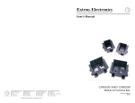
User’s Manual
CTL208CM
www.extron.com
Extron Electronics, USA
Extron Electronics, Europe
Extron Electronics, Asia
Extron Electronics, Japan
1230 South Lewis Street
Anaheim, CA 92805
USA
714.491.1500
Fax 714.491.1517
Beeldschermweg 6C
3821 AH Amersfoort
The Netherlands
+31.33.453.4040
Fax +31.33.453.4050
135 Joo Seng Road, #04-01
PM Industrial Building
Singapore 368363
+65.6383.4400
Fax +65.6383.4664
Daisan DMJ Building 6F
3-9-1 Kudan Minami
Chiyoda-ku, Tokyo 102-0074 Japan
+81.3.3511.7655
Fax +81.3.3511.7656
© 2003 Extron Electronics. All rights reserved.
8-Button Control Panel Module
with Serial Control Output
68-836-01 Rev. A
Printed in the USA
07 03
Precautions
Safety Instructions • English
This symbol is intended to alert the user of important
operating and maintenance (servicing) instructions
in the literature provided with the equipment.
This symbol is intended to alert the user of the
presence of uninsulated dangerous voltage within
the product's enclosure that may present a risk of
electric shock.
Caution
Read Instructions • Read and understand all safety and operating
instructions before using the equipment.
Retain Instructions • The safety instructions should be kept for future
reference.
Follow Warnings • Follow all warnings and instructions marked on the
equipment or in the user information.
Avoid Attachments • Do not use tools or attachments that are not
recommended by the equipment manufacturer because they may be
hazardous.
Consignes de Sécurité • Français
Ce symbole sert à avertir l’utilisateur que la
documentation fournie avec le matériel contient des
instructions importantes concernant l’exploitation
et la maintenance (réparation).
Ce symbole sert à avertir l’utilisateur de la présence
dans le boîtier de l’appareil de tensions dangereuses
non isolées posant des risques d’électrocution.
Attention
Lire les instructions• Prendre connaissance de toutes les consignes de
sécurité et d’exploitation avant d’utiliser le matériel.
Conserver les instructions• Ranger les consignes de sécurité afin de
pouvoir les consulter à l’avenir.
Respecter les avertissements • Observer tous les avertissements et
consignes marqués sur le matériel ou présentés dans la documentation
utilisateur.
Eviter les pièces de fixation • Ne pas utiliser de pièces de fixation ni
d’outils non recommandés par le fabricant du matériel car cela
risquerait de poser certains dangers.
Sicherheitsanleitungen • Deutsch
Dieses Symbol soll dem Benutzer in der im
Lieferumfang enthaltenen Dokumentation
besonders wichtige Hinweise zur Bedienung und
Wartung (Instandhaltung) geben.
Dieses Symbol soll den Benutzer darauf aufmerksam
machen, daß im Inneren des Gehäuses dieses
Produktes gefährliche Spannungen, die nicht isoliert
sind und die einen elektrischen Schock verursachen
können, herrschen.
Achtung
Lesen der Anleitungen • Bevor Sie das Gerät zum ersten Mal verwenden,
sollten Sie alle Sicherheits-und Bedienungsanleitungen genau
durchlesen und verstehen.
Aufbewahren der Anleitungen • Die Hinweise zur elektrischen Sicherheit
des Produktes sollten Sie aufbewahren, damit Sie im Bedarfsfall darauf
zurückgreifen können.
Befolgen der Warnhinweise • Befolgen Sie alle Warnhinweise und
Anleitungen auf dem Gerät oder in der Benutzerdokumentation.
Keine Zusatzgeräte • Verwenden Sie keine Werkzeuge oder Zusatzgeräte,
die nicht ausdrücklich vom Hersteller empfohlen wurden, da diese eine
Gefahrenquelle darstellen können.
Instrucciones de seguridad • Español
Este símbolo se utiliza para advertir al usuario sobre
instrucciones importantes de operación y
mantenimiento (o cambio de partes) que se desean
destacar en el contenido de la documentación
suministrada con los equipos.
Este símbolo se utiliza para advertir al usuario sobre
la presencia de elementos con voltaje peligroso sin
protección aislante, que puedan encontrarse dentro
de la caja o alojamiento del producto, y que puedan
representar riesgo de electrocución.
Precaucion
Leer las instrucciones • Leer y analizar todas las instrucciones de
operación y seguridad, antes de usar el equipo.
Conservar las instrucciones • Conservar las instrucciones de seguridad
para futura consulta.
Obedecer las advertencias • Todas las advertencias e instrucciones
marcadas en el equipo o en la documentación del usuario, deben ser
obedecidas.
Evitar el uso de accesorios • No usar herramientas o accesorios que no
sean especificamente recomendados por el fabricante, ya que podrian
implicar riesgos.
FCC Class A Notice
Warning
Power sources • This equipment should be operated only from the power source
indicated on the product. This equipment is intended to be used with a main
power system with a grounded (neutral) conductor. The third (grounding) pin is
a safety feature, do not attempt to bypass or disable it.
Power disconnection • To remove power from the equipment safely, remove all
power cords from the rear of the equipment, or the desktop power module (if
detachable), or from the power source receptacle (wall plug).
Power cord protection • Power cords should be routed so that they are not likely to
be stepped on or pinched by items placed upon or against them.
Servicing • Refer all servicing to qualified service personnel. There are no userserviceable parts inside. To prevent the risk of shock, do not attempt to service
this equipment yourself because opening or removing covers may expose you to
dangerous voltage or other hazards.
Slots and openings • If the equipment has slots or holes in the enclosure, these are
provided to prevent overheating of sensitive components inside. These openings
must never be blocked by other objects.
Lithium battery • There is a danger of explosion if battery is incorrectly replaced.
Replace it only with the same or equivalent type recommended by the
manufacturer. Dispose of used batteries according to the manufacturer's
instructions.
Note: This equipment has been tested and found to comply with the limits for a
Class A digital device, pursuant to part 15 of the FCC Rules. These limits are
designed to provide reasonable protection against harmful interference when the
equipment is operated in a commercial environment. This equipment generates,
uses and can radiate radio frequency energy and, if not installed and used in
accordance with the instruction manual, may cause harmful interference to radio
communications. Operation of this equipment in a residential area is likely to
cause harmful interference, in which case the user will be required to correct the
interference at his own expense.
Note: This unit was tested with shielded cables on the peripheral devices.
Shielded cables must be used with the unit to ensure compliance.
Avertissement
Alimentations• Ne faire fonctionner ce matériel qu’avec la source d’alimentation
indiquée sur l’appareil. Ce matériel doit être utilisé avec une alimentation
principale comportant un fil de terre (neutre). Le troisième contact (de mise à la
terre) constitue un dispositif de sécurité : n’essayez pas de la contourner ni de la
désactiver.
Déconnexion de l’alimentation• Pour mettre le matériel hors tension sans danger,
déconnectez tous les cordons d’alimentation de l’arrière de l’appareil ou du
module d’alimentation de bureau (s’il est amovible) ou encore de la prise secteur.
Protection du cordon d’alimentation • Acheminer les cordons d’alimentation de
manière à ce que personne ne risque de marcher dessus et à ce qu’ils ne soient
pas écrasés ou pincés par des objets.
Réparation-maintenance • Faire exécuter toutes les interventions de réparationmaintenance par un technicien qualifié. Aucun des éléments internes ne peut être
réparé par l’utilisateur. Afin d’éviter tout danger d’électrocution, l’utilisateur ne
doit pas essayer de procéder lui-même à ces opérations car l’ouverture ou le
retrait des couvercles risquent de l’exposer à de hautes tensions et autres dangers.
Fentes et orifices • Si le boîtier de l’appareil comporte des fentes ou des orifices,
ceux-ci servent à empêcher les composants internes sensibles de surchauffer. Ces
ouvertures ne doivent jamais être bloquées par des objets.
Lithium Batterie • Il a danger d'explosion s'll y a remplacment incorrect de la
batterie. Remplacer uniquement avec une batterie du meme type ou d'un ype
equivalent recommande par le constructeur. Mettre au reut les batteries usagees
conformement aux instructions du fabricant.
Vorsicht
Stromquellen • Dieses Gerät sollte nur über die auf dem Produkt angegebene
Stromquelle betrieben werden. Dieses Gerät wurde für eine Verwendung mit
einer Hauptstromleitung mit einem geerdeten (neutralen) Leiter konzipiert. Der
dritte Kontakt ist für einen Erdanschluß, und stellt eine Sicherheitsfunktion dar.
Diese sollte nicht umgangen oder außer Betrieb gesetzt werden.
Stromunterbrechung • Um das Gerät auf sichere Weise vom Netz zu trennen,
sollten Sie alle Netzkabel aus der Rückseite des Gerätes, aus der externen
Stomversorgung (falls dies möglich ist) oder aus der Wandsteckdose ziehen.
Schutz des Netzkabels • Netzkabel sollten stets so verlegt werden, daß sie nicht
im Weg liegen und niemand darauf treten kann oder Objekte darauf- oder
unmittelbar dagegengestellt werden können.
Wartung • Alle Wartungsmaßnahmen sollten nur von qualifiziertem
Servicepersonal durchgeführt werden. Die internen Komponenten des Gerätes
sind wartungsfrei. Zur Vermeidung eines elektrischen Schocks versuchen Sie in
keinem Fall, dieses Gerät selbst öffnen, da beim Entfernen der Abdeckungen die
Gefahr eines elektrischen Schlags und/oder andere Gefahren bestehen.
Schlitze und Öffnungen • Wenn das Gerät Schlitze oder Löcher im Gehäuse
aufweist, dienen diese zur Vermeidung einer Überhitzung der empfindlichen
Teile im Inneren. Diese Öffnungen dürfen niemals von anderen Objekten
blockiert werden.
Litium-Batterie • Explosionsgefahr, falls die Batterie nicht richtig ersetzt wird.
Ersetzen Sie verbrauchte Batterien nur durch den gleichen oder einen
vergleichbaren Batterietyp, der auch vom Hersteller empfohlen wird. Entsorgen
Sie verbrauchte Batterien bitte gemäß den Herstelleranweisungen.
Advertencia
Alimentación eléctrica • Este equipo debe conectarse únicamente a la fuente/tipo
de alimentación eléctrica indicada en el mismo. La alimentación eléctrica de este
equipo debe provenir de un sistema de distribución general con conductor
neutro a tierra. La tercera pata (puesta a tierra) es una medida de seguridad, no
puentearia ni eliminaria.
Desconexión de alimentación eléctrica • Para desconectar con seguridad la
acometida de alimentación eléctrica al equipo, desenchufar todos los cables de
alimentación en el panel trasero del equipo, o desenchufar el módulo de
alimentación (si fuera independiente), o desenchufar el cable del receptáculo de
la pared.
Protección del cables de alimentación • Los cables de alimentación eléctrica se
deben instalar en lugares donde no sean pisados ni apretados por objetos que se
puedan apoyar sobre ellos.
Reparaciones/mantenimiento • Solicitar siempre los servicios técnicos de personal
calificado. En el interior no hay partes a las que el usuario deba acceder. Para
evitar riesgo de electrocución, no intentar personalmente la reparación/
mantenimiento de este equipo, ya que al abrir o extraer las tapas puede quedar
expuesto a voltajes peligrosos u otros riesgos.
Ranuras y aberturas • Si el equipo posee ranuras o orificios en su caja/alojamiento,
es para evitar el sobrecalientamiento de componentes internos sensibles. Estas
aberturas nunca se deben obstruir con otros objetos.
Batería de litio • Existe riesgo de explosión si esta batería se coloca en la posición
incorrecta. Cambiar esta batería únicamente con el mismo tipo (o su equivalente)
recomendado por el fabricante. Desachar las baterías usadas siguiendo las
instrucciones del fabricante.
Extron’s Warranty
Extron Electronics warrants this product against defects in materials and
workmanship for a period of three years from the date of purchase. In the event of
malfunction during the warranty period attributable directly to faulty
workmanship and/or materials, Extron Electronics will, at its option, repair or
replace said products or components, to whatever extent it shall deem necessary to
restore said product to proper operating condition, provided that it is returned
within the warranty period, with proof of purchase and description of malfunction
to:
USA, Canada, South America,
and Central America:
Extron Electronics
1230 South Lewis Street
Anaheim, CA 92805, USA
Asia:
Extron Electronics, Asia
135 Joo Seng Road, #04-01
PM Industrial Bldg.
Singapore 368363
Europe, Africa, and the Middle East:
Extron Electronics, Europe
Beeldschermweg 6C
3821 AH Amersfoort
The Netherlands
Japan:
Extron Electronics, Japan
Daisan DMJ Bldg. 6F,
3-9-1 Kudan Minami
Chiyoda-ku, Tokyo 102-0074
Japan
This Limited Warranty does not apply if the fault has been caused by misuse,
improper handling care, electrical or mechanical abuse, abnormal operating
conditions or non-Extron authorized modification to the product.
If it has been determined that the product is defective, please call Extron and ask
for an Applications Engineer at (714) 491-1500 (USA), 31.33.453.4040 (Europe),
65.6383.4400 (Asia), or 81.3.3511.7655 (Japan) to receive an RA# (Return
Authorization number). This will begin the repair process as quickly as possible.
Units must be returned insured, with shipping charges prepaid. If not insured,
you assume the risk of loss or damage during shipment. Returned units must
include the serial number and a description of the problem, as well as the name of
the person to contact in case there are any questions.
Extron Electronics makes no further warranties either expressed or implied with
respect to the product and its quality, performance, merchantability, or fitness for
any particular use. In no event will Extron Electronics be liable for direct, indirect,
or consequential damages resulting from any defect in this product even if Extron
Electronics has been advised of such damage.
Please note that laws vary from state to state and country to country, and that
some provisions of this warranty may not apply to you.
Quick Start Guide — CTL208CM
CAUTION
Installation and service must be performed by authorized
personnel only. These units must be installed in
accordance with national and local electrical codes.
Step 1
Power off all devices and disconnect them from the power source,
if necessary.
Step 2
Run the serial cable between the control panel module’s installation
location and the device to be controlled.
Step 3
As necessary, install a wall box, table connector bay, or other miniAAP mounting option into which the control panel module will be
installed.
Step 4
Configure the control panel module’s rear panel DIP switches.
Step 5
Connect a serial cable between the control panel module and a
computer.
Step 6
Connect the external power supply to the control panel module.
Step 7
Program the control panel module’s buttons as desired, using either
the Extron ICS100 control software or the Extron ASCII character
command set.
Step 8
If necessary, set the control panel module’s serial control settings to
match those of the device to be controlled using the Extron ASCII
character command set.
Step 9
Disconnect the serial control cable from the computer and install the
serial control cable between the control panel module and the device
to be controlled.
CTL208CM Control Panel Module • Quick Start Guide
QS-1
Quick Start Guide — CTL208CM, cont’d
Table of Contents
Chapter 1 • Introduction .......................................................... 1-1
Step 10
If the rear of the control panel module will be inaccessible
when the installation is complete, the module should be
powered up and its operation should be tested before the final
installation.
Apply or connect power to all devices in the system.
Step 11
Test the system: Ensure that the controlled device responds as
desired to the control panel module buttons. Correct the
programming or system wiring as necessary. Ensure that you
remove electrical power if you need to change the system wiring.
Step 12
Mount the control panel module into any Extron four-space miniAAP panel.
If the rear of the control panel module will be inaccessible
when the installation is complete, all cables, including the
power connector on the CTL208, must be connected before
the permanent installation.
Step 13
Mount the mini-AAP connector panel as necessary. See chapter 2,
Installation, for further wall mounting details.
Step 14
Restore power to all devices. The installation is now complete.
About the CTL208CM ........................................................... 1-2
Features ...................................................................................... 1-2
Chapter 2 • Installation ............................................................. 2-1
Installation Overview ......................................................... 2-2
UL Requirements for Wall Box Installation .............. 2-4
Wall Mounting Site Preparation .................................... 2-4
Device Configuration .......................................................... 2-7
Wall Mounting ......................................................................... 2-8
Rear Panel Setup ................................................................... 2-9
Chapter 3 • Operation ................................................................ 3-1
Button Modes ........................................................................... 3-2
Send Programmed Commands ....................................... 3-2
Factory Reset ........................................................................... 3-4
Chapter 4 • Serial Communications .................................. 4-1
ICS100 Windows Control Program ................................ 4-2
System requirements ............................................................ 4-2
Installing the software .......................................................... 4-2
Starting the program ............................................................ 4-3
Using the software to program the CTL208CM ................... 4-5
Using the help system ........................................................... 4-8
Serial Commands ................................................................... 4-9
Communications protocols .................................................... 4-9
Command and response structure ........................................ 4-9
Addressing the unit ............................................................... 4-9
Control panel module responses ......................................... 4-10
Using the command/response table ................................... 4-10
Symbols ........................................................................... 4-11
Command/response table for programming the CTL208 ... 4-13
QS-2
CTL208CM Control Panel Module • Quick Start Guide
CTL208CM Control Panel Module • Table of Contents
i
Table of Contents, cont’d
Appendix • Reference Information .................................. A-1
Specifications ......................................................................... A-2
Parts List .................................................................................... A-3
Included parts ........................................................................ A-3
Mini-AAP mounting options ................................................. A-3
Wall mounting solutions ................................................... A-3
Architectural solutions ....................................................... A-4
Table solutions .................................................................. A-4
Wall mounting hardware ..................................................... A-4
CTL208CM Control Panel Module
1
Chapter One
Introduction
About the CTL208CM
68-836-01 Rev. A
Printed in the USA
07 03
All trademarks mentioned in this manual are the properties of their respective
owners.
ii
CTL208CM Control Panel Module • Table of Contents
Features
Introduction, cont’d
Introduction
About the CTL208CM
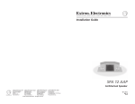
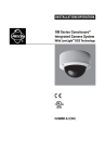
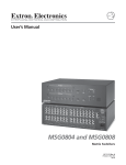
The Extron CTL208CM is a programmable 8-button control
panel module that can be connected to any serial-controlled
device (figure 1-1). Each button can store one or two command
strings that are programmed with either ASCII or hex
characters. When you push the button, the control panel
module issues the programmed ASCII or hex string to the
connected device.
Four operating modes per button — Each button can be set to
one of four operating modes: single (default), toggle,
press/release, or continuous
•
Single mode — The control panel module sends the
primary ASCII or hex string programmed to a button
when you press that button.
•
Toggle mode — The control panel module sends the
primary ASCII or hex string programmed to a button
when you press that button. The module sends the
secondary string when you press the button a second
time.
Button grouping — Buttons that are in toggle mode
can also be assigned to a group. When one button is
selected, the control panel module deselects all other
buttons in the group.
Button timeout — Buttons that are in toggle mode
can be further set to automatically toggle off after a
user-defined period of time, up to 255 minutes.
RS-232
Projector
Control
Extron
CTL208CM
Control Module
Projector on/off control
Projector input switching
Projector volume control
VCR
DVD
Laptop
Figure 1-1 — Typical CTL208CM application
The control panel module is incorporated into a four space miniAAP enclosure that can be mounted into a variety of Extron
mini-AAP architectural options, including wall plates (such as
the CPM101), table-mounted connector bays (such as the
CPM208), or an interface or other device that has its own miniAAP mounting bays (such as the CIA111).
The control panel module requires 9VDC to 13VDC and ships
with an external 12VDC power supply.
Features
Eight buttons with indicator LEDs — Each button can be
programmed with one or two (primary and secondary)
ASCII or hex strings.
1-2
CTL208CM Control Panel Module • Introduction
•
Press/release mode — The control panel module sends
the primary ASCII or hex string programmed to a button
when you press that button and the secondary string
when you release the button.
•
Continuous mode — The control panel module
repeatedly sends the primary ASCII or hex string
programmed to a button for as long as you press and
hold that button.
Serial programming — The buttons are programmable, under
RS-232, RS-422, and RS-485 serial control, using either the
included Extron ICS100 control software or the Extron
ASCII character command set.
Serial outputs — The control panel module outputs the ASCII
or hexadecimal strings to the connected device using
either RS-232, RS-422, or RS-485 serial protocol.
Four space mini-AAP enclosure — The CTL208 can be mounted
into a variety of Extron mini-AAP architectural options,
such as wall plates, table-mounted connector bays, or
interfaces with their own mini-AAP mounting bays.
2 colors — Available in either a black or white finish.
Custom engraved front panels — Extron can create custom
front panels, in either the black or the white finish, to
neatly and professionally label each button. Contact the
Extron S3 Sales & Technical Support Hotline to order the
panels.
CTL208CM Control Panel Module • Introduction
1-3
Introduction, cont’d
CTL208CM Control Panel Module
2
Chapter Two
Installation
Installation Overview
UL Requirements for Wall Box Installation
Wall Mounting Site Preparation
Device Configuration
Wall Mounting
Rear Panel Setup
1-4
CTL208CM Control Panel Module • Introduction
Installation, cont’d
Installation
Installation Overview
CAUTION
If desired, order a custom engraved front panel. Contact
the Extron S3 Sales & Technical Support Hotline to order
the panel.
2
Power off all devices and disconnect them from the
power source, if necessary.
3
Run a serial cable between the site where the CTL208CM
control panel module will be installed and the site of the
serial-controlled device.
4
For installation in a wall or furniture, prepare the site:
cut a hole in the surface, install the electrical box or
mounting bracket, and prepare the cables. See Wall
Mounting Site Preparation in this chapter. See appendix A,
Reference Information, for a partial list of devices that can
accept four space mini-AAPs.
6
For other installations, install a tabletop or in-table
connector bay, or other mini-AAP mounting option.
Refer to the manual for the device in which the control
panel module will be installed. See appendix A, Reference
Information, for a partial list of devices that can accept four
space mini-AAPs.
8
2-2
10
If necessary, configure the control panel module’s serial
control protocol settings (baud rate, data bits, and stop
bits) to match those of the device to be controlled. See
ICS100 Windows Control Program and/or Serial Commands
in chapter 4, Serial Communications, for details.
11
If necessary, reconfigure the control panel module’s rear
panel DIP switch 1 to match the serial protocol (RS-232,
RS-422, RS-485) of the device to be controlled. See Rear
Panel Setup, in this chapter for details.
12
If the computer, control panel module, and the device to
be controlled are not part of an RS-485 serial port daisy
chain, disconnect the serial control cable from the
computer and install the serial control cable between the
control panel module and the device to be controlled.
If the rear of the control panel module will be inaccessible
when the installation is complete, the operation of the
module should be tested before the final mounting.
13
Apply or connect power to all devices in the system.
14
Test the system: Ensure that the controlled device
responds as desired to the control panel module buttons.
If necessary, correct the programming and/or the system
wiring. Ensure that you remove electrical power if you
need to change the system wiring. Test the system again.
15
Disconnect power from the control panel module and
other devices.
16
Mount the control panel module into any Extron fourspace mini-AAP connector panel.
Connect a serial cable between the control panel module
and a computer. See Rear Panel Setup, in this chapter for
details.
Alternatively, you can connect the control panel module
to an RS-485 serial port daisy chain that includes the
programming computer and the device to be controlled.
In a daisy-chain configuration, you can make changes to
the control panel module’s button programming as
needed, without removing the panel from its installation.
7
Program the control panel module’s buttons as desired,
using either the Extron ICS100 control software or the
Extron serial character command set. See ICS100 Windows
Control Program and/or Serial Commands in chapter 4, Serial
Communications, for details.
Installation and service must be performed by
authorized personnel only. UL Listed electrical
boxes are recommended. See UL Requirements
for Wall Box Installation in this chapter.
1
5
9
If necessary, configure the control panel module’s rear
panel DIP switches to match the serial protocol (RS-232,
RS-422, RS-485) of the computer used to program the
control panel module. See Rear Panel Setup, in this chapter
for details.
Connect the power source to the control panel module.
See Rear Panel Setup, to wire the power connector.
CTL208CM Control Panel Module • Installation
If the rear of the control panel module will be inaccessible
when the installation is complete, all cables, including
the power connector on the CTL208, must be connected
before the permanent installation.
17
Mount the mini-AAP connector panel to the mini-AAP
mounting option as necessary. See Wall mounting in this
chapter for details about wall mounting the panel.
18
Restore power to all devices.
CTL208CM Control Panel Module • Installation
2-3
Installation, cont’d
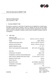
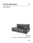
UL Requirements for Wall Box Installation
The following Underwriters Laboratories (UL) requirements
pertain to the installation of the CTL208CM into a wall or
furniture (figure 2-1).
Installation
Cable
The installation must conform to national and local electrical
codes and to the equipment’s size requirements.
Installation using a UL listed wall box (available from Extron) is
recommended for most mounting options, but the optional wall
mounting bracket can be used instead. All wall boxes must be
at least 2.5” (6.4 cm) deep.
Before using the wall mounting bracket, verify that the
installation conforms to national and local electrical
codes.
Conduit
Prepare the site as follows:
H.
IFT
SH
1.
If your wall box or mounting bracket includes a paper
template, cut out the indicated portions of the template. If
the wall box or mounting bracket does not include a
template, use the wall box or bracket itself to size the hole.
2.
Place the template, wall box, or mounting bracket against
the installation surface, and mark the guidelines for the
opening on the wall or furniture.
3.
Cut out the wall/furniture material from the marked area.
4.
Check the opening size by inserting the wall box or
mounting bracket into the opening. The box or bracket
should fit easily into the opening. Enlarge or smooth the
edges of the opening if needed.
5a.
If you are using a wall box, feed cables through the wall
box punch-out holes, and secure them with cable clamps to
provide strain relief.
CT
UT
LE
SE
INP
X
MIN/
MA
1
2
DIO
AU
2
NIT
2
UT
INP
UT
INP
1
SP
i WIT
78
1
S
OW
OR
LL
NIT
FO
MO
UT
INP
2.5"
OR
MO
DIO
AU
™
H AD
Mx
B4
RG
1
Extron
CTL208CM
Control Module
Extron
RGB 478 Mxi
Interface
Figure 2-1 — CTL208CM in a four-gang wall box
1.
These units are not to be connected to a centralized DC
power source or used beyond their rated voltage range.
2.
These units must be installed in UL listed junction boxes.
3.
These units must be installed with conduit in accordance
with the National Electrical Code.
Wall Mounting Site Preparation
The control panel module can be mounted in a wall-mountable
four space mini-AAP A/V connector panel (such as a one-gang
CPM101) and then set into a wall with either a standard studmounted wall box or with a wall mounting bracket (IN9181).
The control panel module can also be mounted to any wallmountable Extron device that incorporates a four space A/V
mini-AAP connector panel, such as a three-gang RGB 468 Mxi.
See Mini-AAP mounting options in Appendix A, Reference
Information, for a partial list of devices that can accept four space
mini-AAPs.
Choose a location that allows power cable and serial control
cable runs without interference. Allow enough depth for the
wall box and the cables. You should install the cables in the wall
or furniture, with or without conduits, before installing the
mounting bracket or wall box.
2-4
CTL208CM Control Panel Module • Installation
Exposed cable shields (braids or foil) are potential sources
of short circuits. Trim back and/or insulate shields with
heat shrink (figure 2-2).
Screw
Braided Shield
Metal Wall Box
Cable Clamp
Install Cable
Foil Shield
Figure 2-2 — Grounding outer braided and foil shields
To prevent short circuits, the outer foil shield can be
cut back to the point where the cable exits the cable
clamp. Both braided and foil shields should be
connected to an equipment ground at the other end
of the cable.
CTL208CM Control Panel Module • Installation
2-5
Installation, cont’d
5b.
If you are using a wall box, insert the wall box into the
opening, and attach it to the wall stud or furniture with
nails or screws, leaving the front edge flush with the outer
wall or furniture surface (figure 2-3). The illustration
applies to both two-gang and four-gang wall boxes.
clips that fasten the ring to the wall or furniture (figure 24).
Wall
Wall Stud
Extron
Push Mounting
Tabs Forward
Installation
Cable
IN9181 Wall
Mounting Bracket
Cable Clamp
Screws or Nails
Wall opening
flush with
edge of box
Figure 2-4 — Attaching a mounting bracket to a wall
Device Configuration
The rear of the control panel module will be inaccessible
after installation.
Figure 2-3 — Attaching a wall box to a stud
If attaching the wall box to wood, use four #8 or #10
screws or 10-penny nails. A minimum of 1/2 inch (1.3 cm)
of screw threads must penetrate the wood.
If attaching the wall box to metal studs or furniture, use
four #8 or #10 self-tapping sheet metal screws or machine
bolts with matching nuts.
6.
2-6
1.
Cable the control panel module and set the DIP switches.
See Rear Panel Setup in this chapter.
2.
Program the buttons. See chapter 4, Serial Communications,
to program the control panel module.
3.
Test the control panel module before installing it into the
wall box.
If you are using a mounting bracket, follow the directions,
if any, that came with the mounting bracket to attach the
CTL208CM Control Panel Module • Installation
CTL208CM Control Panel Module • Installation
2-7
Installation, cont’d
Wall Mounting
The physical orientation of the control panel module is
important when you are programming and operating the
buttons. Buttons 1 and 5 (figure 2-5) are on top when
the CTL208 is right-side up. Orient the CTL208 so that
the text on the rear of the unit is right-side up to
determine the top of the module.
Button
number
Button
number
1
5
2
6
3
7
4
8
2.
If not already accomplished, attach the power and serial
cables to the rear of the control panel module. Power on
the control panel module now if the external power supply
cannot be accessed once the module is mounted.
3.
Mount the CPM101 or other mini-AAP panel (with the
attached control panel module) to the wall box or
mounting bracket using the two included mounting
screws (figure 2-6).
Figure 2-6 shows a wall box installation. Mounting the
mini-AAP panel to a mounting bracket is identical.
Power on all devices.
4.
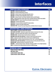
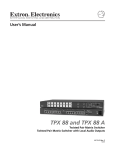
Rear Panel Setup
All of the connectors and DIP switches necessary for connecting
and configuring the CTL208CM are on the rear panel (figure 2-7).
GND
TX-
3
Figure 2-5 — Button locations
1.
Sandwich the mini-AAP panel (such as a CPM101)
between the control panel module (without its front panel)
and the module’s front panel. Secure the front panel to the
control panel module with the included #4-40 screws
(figure 2-6).
RXRX+
1 2 3 4 5 6
2
1
ON
0
1
2
3
4
5
6
SWITCH
FUNCTION
1
SERIAL MODE
1- RS485/RS422
0 - RS232
2&3
TERMINATION
(END UNIT)
1 - 120 OHMS
0 - OPEN
4
RESERVED
5
6
Extron
CPM101
1
TX+
+
9 - 13 VDC
@
500MA
SETTING
FACTORY RESET 0 - NORMAL
SPARE
Figure 2-7 — Rear panel view
A/V Connector
Panel
Wall opening
flush with
edge of box
Extron
CTL208CM
Front Panel
Control Module
Figure 2-6 — Attaching the mini-AAP panel to a wall
box
2-8
CTL208CM Control Panel Module • Installation
CTL208CM Control Panel Module • Installation
2-9
Installation, cont’d
Serial port connector — This port is a 3.5 mm, 5-pole captive
screw connector for serial RS-232, RS-422, or RS-485
communications. Connect to the port as shown in figure 2-7.
1
The default settings for all switches for an RS-232
connection is off (0).
DIP switch 3 should be turned on for an RS-485 full
duplex connection only, and only if the CTL is the first
or last unit in a daisy chain.
The port serves two functions:
•
Connects the control panel module to a computer to
program the module’s buttons.
•
Connects the control panel module to the device to be
controlled, such as a projector or switcher.
3
RX+
RX-
TX+
TX-
GND
Half duplex RS-485
RX+
RX-
TX+
TX-
GND
Full duplex RS-422/485
RX+
RX-
TX+
TX-
GND
RS-232
DIP switch 5 is a factory reset control. See Factory Reset in
chapter 3, Operation.
2
RX
3
RX+
3
RX+
3
TX
7
RX-
7
RX-
5
GND
2
TX+
2
TX+
6
TX-
6
TX-
5
GND
5
GND
1
GND
1
GND
Pin #
Computer Serial
Port (DB-9)
Pin #
Computer Serial
Port (DB-9)
Connect the control panel module to a device with
auxiliary 12VDC outputs, such as an Extron MSV0502-3 or
MSV0804-3 matrix switcher. Figure 2-8 shows how to wire
the power connector.
•
Connect the included 12VDC external power supply to the
2-pole female direct insertion captive screw connector.
Figure 2-8 shows how to wire the power connector.
A
A
SECTION A–A
Power Supply
Output Cord
RS-485 implementation may vary between computers or
control systems. Connect the control cable as shown in
figure 2-7. If the serial communications link with the
control panel module switcher does not work, try
reversing the polarity of the TX and RX signal lines.
Serial port configuration DIP switches —
DIP switch 1 configures the control panel module’s serial port to
operate as RS-232, RS-422, or RS-485. DIP switches 2 and 3 are
used to terminate the RX and TX lines when the control panel
module is at the end of a line of serial devices. The table below
defines the switch positions.
Switch
Function
RS-485
position
1
Serial mode
On (1)
2
Rx
On (1)*
On (1)*
termination
or Off (0).
or Off (0).
On (1) if full duplex*
Tx
Off (0)
termination or Off (0) if half duplex.
3
•
Pin #
Computer Serial
Port (DB-9)
Figure 2-7 — Serial port pin assignments
2
Captive screw power connector — Power the control panel
module one of two ways:
Figure 2-8 — Power connector wiring
Do not tin the stripped power supply leads before
inserting them into the captive screw connector. Tinned
leads are not as securely attached as untinned leads and
could slip out.
The two power supply leads must be kept separated
while the power supply is plugged into an electrical
outlet. Remove power before wiring.
To verify correct polarity before connection, check the power
supply’s no load output with a voltmeter.
RS-422
RS-232
position position
On (1)
Off (0)
Off (0)
Off (0)
* If the CTL is the last unit in a daisy chain.
2-10
CTL208CM Control Panel Module • Installation
CTL208CM Control Panel Module • Installation
2-11
Installation, cont’d
CTL208CM Control Panel Module
3
Chapter Three
Operation
Button Modes
Send Programmed Commands
Factory Reset
2-12
CTL208CM Control Panel Module • Installation
Operation, cont’d
Operation
Button Modes
Send Programmed Commands
Before a control panel module button is programmed, it has no
function. See chapter 4, Serial Communications, to program the
buttons. Programming includes:
•
Assigning the program string(s) to the button. One or
two strings (primary and secondary) can be assigned to
each button.
•
Setting each program string to be either ASCII or
hexadecimal.
•
Setting the mode for each button. The mode for each
button can be any one of the following:
Single — Sends the primary program string when
pushed.
Toggle — Sends the primary program string when
pushed once. Sends the secondary program string
when pushed a second time.
•
Press/release— Sends the primary program string
when pushed. Sends the secondary program string
when released.
Continuous — Sends the primary program string
when pressed and continues to repeat sending the
primary command string for as long as the button is
held.
For toggle mode, if desired, setting a group or timeout:
Group — Buttons that are in toggle mode can also be
assigned to a group. When one button is selected,
the control panel module deselects all other buttons
in the group.
Button
number
Button
number
1
5
2
6
3
7
4
8
Figure 3-1 — Power connector wiring
The actions that occur when you push a programmed button
vary, depending on how the button is programmed.
•
Single mode — Push the button to send the primary
program string. The button’s LED flashes once.
•
Toggle mode — Push the button to send the primary
program string. The button’s LED lights. Push the
button a second time to send the secondary string. The
button’s LED goes out.
•
Press/release mode — Press and hold the button to send
the primary program string. The button’s LED lights.
Release the button to send the secondary string. The
button’s LED goes out.
•
Continuous mode — Press and hold the button to
repeatedly send the primary program string. The
button’s LED lights. Release the button to stop sending
the string. The button’s LED goes out.
•
Two or more buttons set to toggle mode and grouped —
Push a button in the group to send that button’s primary
program string. That button’s LED lights. If another
button in the group was selected, that button is deselected
(its LED goes out).
Groups cannot be assigned to buttons that
are set to operate with a timeout.
Timeout — Buttons that are in toggle mode can be
further set to automatically toggle off after a userdefined period of time, up to 255 minutes.
Timeouts cannot be assigned to buttons
that are set to operate in groups.
When buttons are grouped, the CTL208 does not send
the secondary command string for the button it deselects
when you select a new button in the group.
3-2
CTL208CM Control Panel Module • Operation
CTL208CM Control Panel Module • Operation
3-3
Operation, cont’d
•
Toggle mode and a timeout set — Push a button to send
the primary program string. The button’s LED lights.
When you push the button a second time or when the
timeout expires, the control panel module sends the
secondary program string. The button’s LED goes out
If you push the button a third time, the timeout interval
starts over; that is, if the timeout is set to 30 minutes,
the control panel module will send the secondary string
30 minutes later.
The CTL208’s clock is always running and the
programmed timeout occurs on the full minute. Thus,
the timeout can occur up to 59 seconds earlier than the
number of minutes programmed. Over the length of the
average timeout setting, this “early” timeout is
considered of no consequence.
Factory Reset
With power removed, set rear panel DIP switch 5 to on (up).
Reapply power. Set switch 5 back to off (down). The DIP switch
factory reset performs the following functions:
•
Resets the control panel module’s serial port to 9600
baud, no parity, Xoff, and half duplex mode
•
Resets the module’s address to 97;
•
Enables the front panel
•
Erases all button codes
•
Resets all buttons to single mode
•
Resets all button groups and timeouts to 0.
Ensure that you reset switch 5 to off (down). If you
leave the switch on (up), the control panel module will
reset every time you power it on.
3-4
CTL208CM Control Panel Module • Operation
CTL208CM Control Panel Module
4
Chapter Four
Serial Communications
ICS100 Windows Control Program
Serial Commands
Serial Communications,
cont’d
Serial
Communications
The control panel module must be programmed before it can be
operated. Programming can include setting several serial port
variables to match the device to be controlled and includes
entering the primary and secondary (if applicable) code for each
button.
You can program the control panel module either by using the
ICS100 windows control program or by sending individual
ASCII commands. Both programming methods require that a
serial port cable be connected between a computer and the
control panel module’s serial port.
8.
The next InlineControl Setup window that appears
indicates when setup is complete. Click Ok.
Starting the program
Start the control program and establish communications with
the CTL208 as follows:
1.
Click Start > Programs > Extron > ICS100. The control
program window (figure 4-1) appears.
The CTL208 will not respond until it has been contacted
with the valid address; after a moment, the program
reports a failure to connect (figure 4-1).
ICS100 Windows Control Program
The ICS100 Control Program, a graphical control software for
Windows, provides a way to program the control panel module.
System requirements
•
Operating system —
Windows 95 / 98 / ME / NT / 2000 / XP / XP Pro
If using Windows NT, Service Pack 6 must be installed.
•
Hardware — Pentium 150 or faster CPU
•
Memory — Minimum: 128 MB
Recommended: 256 MB
•
Screen resolution — Minimum: 800 x 600
Recommended: 1024 x 768
Figure 4-1 — ICS100 program window and warning
•
Disk space — 5 MB
2.
The control panel module’s serial port is factoryconfigured to 9600 baud, no parity, no flow control, halfduplex mode. If desired, serial port settings can be
changed from within the ICS100 program.
Installing the software
The control program is contained on a CD-ROM, and must be
installed on the hard drive.
1.
Click Start > Run.
2.
Click the Browse button. An open file window appears.
3.
Navigate to the drive or folder that contains the software.
4.
Double click the setup icon.
5.
Click Ok in the Run window.
6.
Click Ok in the InlineControl Setup window.
7.
Click the icon button in the next InlineControl Setup to
install the software in the default (Extron) directory in the
Program group.
If you want to specify a different directory, click on the
Change Directory button.
4-2
CTL208CM Control Panel Module • Serial Communications
Click OK.
3.
If you need to change serial port settings, click
Communications > Comm Port > Comm 1 (or the correct Comm
port). The Serial Port Setup window appears (figure 4-2).
Figure 4-2 — Serial Port Setup window
CTL208CM Control Panel Module • Serial Communications
4-3
Serial Communications, cont’d
a.
Click in the appropriate radio buttons to select the
desired settings.
b.
Click Ok.
If you change the serial protocols, communications
between the computer and the control panel module are
lost until the computer is updated to match the new
control panel module settings).
4.
Using the software to program the CTL208CM
Use the control program to program the CTL208 buttons as
follows:
1.
Click Inline Model > Select Address. The Addresses window
(figure 4-3) appears.
Click Inline Model > Query Hardware to configure the
ICS100 program to communicate with the CTL208 and to
confirm that communications have been established with
the control panel module. The Connected window
appears (figure 4-4).
Figure 4-4 — Connected window
Figure 4-3 — Addresses window
The control panel module must be addressed before it
will accept and respond to commands. The addressing
operation routes setup information to a particular unit
on a network and enables command responses. Once the
control panel module is addressed, it can accept an
unlimited number of commands. If a different unit is
addressed, the CTL208 ignores subsequent commands
until it is addressed again.
Click Ok.
2.
Click Controls > Control Panel. The CTL208 control panel
(figure 4-5) appears.
The factory-installed default address is 97, but this
number can be changed. The control panel module can
also take commands after receiving a broadcast address of
00, but it will not send responses. Broadcast addressing
is for multiple units on an RS-485 serial line in half
duplex mode.
After you are finished sending commands to the control
panel module, always end the session by selecting a
different address than the one assigned to the CTL208.
This prevents the module from responding to commands
meant for another unit.
4-4
5.
Click and drag on the slider or click the scroll up ( ) or
down ( ) button until the desired address is visible.
6.
Click on the desired address. The default address is 97.
7.
Click Ok.
CTL208CM Control Panel Module • Serial Communications
Figure 4-5 — CTL208 control panel window
CTL208CM Control Panel Module • Serial Communications
4-5
Serial Communications, cont’d
3.
4.
For each button to be programmed, click the pull down
menu above the numbered panel button and select a
mode: 0 Single, 1 Toggle, 2 Press/Release, or 3
Continuous. See Button Modes in chapter 3, Operation, for
definitions of the various button modes.
For each button to be programmed, click the numbered
panel button.
a.
5.
Selecting the Hex radio button causes the CTL to
convert the primary code that you will enter in step 6 to
a hex value before saving it. Then, when you press the
button, the CTL sends the hex value.
6.
If you selected toggle mode in step 3, the Toggle
Mode Timeout window appears (figure 4-6).
In the Button Codes window (figure 4-7), enter the desired
primary code in the Code 1 window.
Codes that are intended to be hex codes must be in pairs.
Use a leading 0 if necessary. Letters must be upper case.
Many common keyboard key codes, which are often
required for ASCII or hex control of another device, are
available in the selection buttons on the bottom of the
window. Selections made in these buttons are displayed
in the Code window as |.
Figure 4-6 — Toggle Mode Timeout window
Click and drag the slider to select the number of
minutes (1 to 255) interval you want to pass before
the button times out. Select 0 for no button timeout.
In the Button Codes window, click in the ASCII or Hex
radio button to select the appropriate format.
Click Program to save the command.
7.
Timeouts cannot be assigned to buttons that are set to
operate in groups.
In the Button Codes window, click in the ASCII or Hex
radio button to select the appropriate format.
Selecting the Hex radio button causes the CTL to
convert the secondary code that you will enter in step 8
to a hex value before saving it. Then, when you press
the button, the CTL sends the hex value.
Click the in the upper right corner of the window
to save the timeout value and close the window. The
Button Codes window appears (figure 4-7).
8.
In the Button Codes window, if applicable, enter the
desired secondary code in the Code 2 window.
Codes that are intended to be hex codes must be in pairs.
Use a leading 0 if necessary. Letters must be upper case.
The control panel module will only send the secondary
code for a button if that button is in toggle or press/
release mode.
Click Program to save the command.
Figure 4-7 — Button Codes window
b.
4-6
If you selected single, press/release, or continuous
mode in step 3, the Button Codes window appears
(figure 4-7).
CTL208CM Control Panel Module • Serial Communications
9.
Click the in the upper right corner of the window to
close the window.
10.
For each button set to toggle mode, if desired, click in the
Group 1 or 2 checkbox to assign the button to a group.
See Button Modes in chapter 3, Operation, for a definition of
a group.
CTL208CM Control Panel Module • Serial Communications
4-7
Serial Communications, cont’d
Buttons must be set to operate in toggle mode to assign
groups.
Groups cannot be assigned to buttons that are set to
operate in toggle mode and are assigned a timeout value.
11.
When all of the desired programming changes are made,
click the Program button at the bottom of the window to
send all of the programming entries to the control panel
module.
End the session by selecting a different address than the
one assigned to the CTL208. This prevents the module
from responding to commands meant for another unit.
12.
Click Inline Model > Select Address. The Addresses
window (figure 4-2) appears.
13.
Click and drag on the slider or click the scroll up ( ) or
down ( ) button until an address other than the CTL208’s
address is visible.
14.
Click on the desired address.
15.
Click Ok.
16.
If necessary, reconfigure the comm port.
The communications protocols of the control panel
module should match the optimum protocols of the device
to be controlled.
17.
18.
If you need to change serial port settings to match the
serial communication protocol of the device to be
controlled, click Communications > Comm Port > Comm 1 (or
the correct Comm port). The Serial Port Setup window
appears (figure 4-3).
a.
Select the desired settings by clicking in the
appropriate radio buttons.
b.
Click Ok.
Click the in the upper right corner of the startup
window to exit the program.
Using the help system
For information about program features, you can access the
help program in the following ways:
4-8
•
From within the ICS100 startup window, click on the Help
entry on the task bar.
•
From within the Button Codes window, press the F1 key.
CTL208CM Control Panel Module • Serial Communications
Serial Commands
Communication protocols
The control panel module’s serial port is factory-configured to
9600 baud, no parity, no flow control, half-duplex mode.
If you change the serial protocols, communications between the
computer and the control panel module are lost until the
computer is updated to match the new control panel module
settings.
The communications protocols of the control panel
module should match the protocols of the device to be
controlled.
Command and response structure
Valid commands consist of a leading delimiter, one or more
characters in a command code, and an ending delimiter. The
control panel module’s response to an RS-232 command also
consists of a leading delimiter, a command code, and an ending
delimiter.
The control panel module’s leading delimiter code is always a
left bracket ( [ ). The ending delimiter code is always a right
bracket ( ] ).
Example: [CPp@] — where “[“ is the leading code, “CPp@” is
the command (reset the serial port to default values), and “]” is
the ending code.
Addressing the unit
The control panel module must be addressed before it will
accept and respond to commands. The address packet ([CC##],
where ## is the 2-digit address ) routes setup information to a
particular unit on a network and enables command responses.
Once the control panel module is addressed, it can accept an
unlimited number of commands. If a different unit is addressed,
the CTL208 ignores subsequent commands until addressed
again.
The factory-installed default address is 97, but this number can
be changed. The control panel module can also take commands
after receiving a broadcast address of 00, but it will not send
responses. Broadcast is for multiple units on an RS-485 serial
line in half duplex mode.
After you are finished programming the control panel module,
always terminate the session by sending an address packet to
another unit with a different address. This prevents the module
from responding to commands meant for another unit.
CTL208CM Control Panel Module • Serial Communications
4-9
Serial Communications, cont’d
Symbols
Control panel module responses
When a command is valid, the module performs the command
and sends the following response:
X1
=
Line feed
=
Address number
[R0 {address} {echo of the command sent}]
The very first command that you send to the control panel module
must be the connect, [CC X1 ], command, where X1 is the module’s
address. The control panel module will not accept other
commands or respond until it has been addressed.
When a command is invalid, either because the command is not
recognized or contains invalid parameters, the module sends
the following response:
[R1 {address} {echo of the command sent}]
The very last command that you send to the control panel module
should be the connect, [CC X1 ], command, where X1 is a different
address. This prevents the control panel module from accepting
and responding to commands for other devices.
Using the command/response table
The command/response table begins on page 4-13. Upper or
lower case letters are acceptable in the command field. The
table below shows the hexadecimal equivalent of each ASCII
command.
X2
=
Space
4-10
CTL208CM Control Panel Module • Serial Communications
Button number and string (primary or secondary) (figure 4-8)
Buttons 1 and 5 are closest to the top of the CTL208. Orient the
CTL208 so that the text on the rear of the unit is right-side up to
determine the top of the module.
ASCII to HEX Conversion Table
Symbols, defined starting on page 4-11, are used throughout the
table to represent variables in the command/response fields.
Command and response examples are shown throughout the
table.
00 - 98 (00 addresses all units but individual units do
not respond, 97 is the factory-installed default).
Button
number
Button
number
1
5
2
6
3
7
4
8
Figure 4-8 — Button numbers
X2
X2
s must be 2-digit numbers.
# Button/string
01 = 1/primary
02 = 2/primary
03 = 3/primary
04 = 4/primary
05 = 5/primary
06 = 6/primary
07 = 7/primary
08 = 8/primary
X2
# Button/string
11 = 1/secondary
12 = 2/secondary
13 = 3/secondary
14 = 4/secondary
15 = 5/secondary
16 = 6/secondary
17 = 7/secondary
18 = 8/secondary
X3
=
ASCII button code Up to 128 alphanumeric characters.
If you need to use the bracket delimiters in a stored
ASCII command, you need to use the insert
brackets feature. Under this feature, one character
replaces the left bracket ( [ ) and another character
replaces the right bracket ( ] ). The default values
are a single quote mark ( ‘ ) in place of the left
bracket and a double quote ( “ ) in place of the right
bracket. The CTL208 replaces the characters with
the bracket delimiters in the stored ASCII or hex
command string.
X4
=
Bracket position
1 = left bracket, 2 = right bracket.
CTL208CM Control Panel Module • Serial Communications
4-11
= Duplex mode: 0 = full duplex, 1 = half duplex (default)
X15
= Front panel and responses: 0 = disable, 1 = enable (default)
X16
= Reset level: 0 = reset the serial port to 9600 baud, no parity, Xoff, and
half duplex mode; reset the address to 97; and enable
the front panel.
1 = perform all of the same resets AND erase all button
codes, reset all buttons to single mode, and reset all
button groups and timeouts to 0. This reset is identical
to the DIP switch reset, see Factory Reset in chapter 3,
Operation.
X17
= Architectural information:
C208•{serial #}•{Rev level}•{firmware #}•{firmware Rev level}•{available
baud rates}1200,2400,4800,9600,19200,38400•{2 bytes for future use}
4-12
CTL208CM Control Panel Module • Serial Communications
Set the X5 character as the insert brackets
character for the left or right bracket ( X4 ).
Set the single quote ( ‘ ) character as the insert
brackets character for the left bracket.
The replacement characters are listed in the
order {left}{right}.
Program button X2 to X6 .
Programs button 3’s primary code to send the
hex command string 0F.
X5
X5
•]
•]
R0• X1 •PCHp X2 X6 •]
R0•97•PCHp030F•]
X14
[PCHp X2 X6 ]
[PCHp030F
= Flow control mode: 0 = Xoff (default), 1 = Xon
Store hex code to a button
Example:
X13
R0• X1 •BKT X5
= Parity mode: 0 = no parity (default), 1 = odd parity, 2 = even parity
[BKT?]
X12
View insert brackets characters
2 = 4800
5 = 38,400
R0•97•BKT1’]
1 = 2400
4 = 19,200
[BKT1’]
= Baud rate
0 = 1200
3 = 9600 (default)
Example:
X11
R0• X1 •BKT X4
Timeouts cannot be assigned to buttons that are set to operate in
groups.
X5 ]
0 or 1 - 255 (minutes). 0 = no timeout.
[BKT X4
= Button timeout interval
Brackets inserted using the insert brackets feature appear as brackets when you use view command.
X10
Set an insert brackets character
Groups cannot be assigned to buttons that are set to operate in
timeout mode.
R0• X1 •PCLp X2 ?• X3 ]
0 = Not assigned, 1 = Assigned
[PCLp X2 ?]
Button group assignment
View a button’s ASCII code
=
R0• X1 •PCLp X2 X3 •]
R0• X1 •PCLp02’CH3”•]
X9
[PCLp X2 X3 ]
[PCLp02’CH3”
1 or 2
Button code programming
Button group number
Store ASCII code to a button
Example:
=
[R0• X1 •ADDR X1 •]
[R0•95•ADDR95•]
[R0• X1 •ADDR@•]
X8
[ADDR X1 ]
[ADDR95]
[ADDR@]
1 = Toggle mode
3 = Continuous
Specify address number
Example:
Reset address to factory default
Button mode
0 = Single mode
2 = Press/release
Connect the host computer to the addressed
unit. This command is case sensitive.
Change the CTL208’s address to X1 .
Change the address number to 95.
Reset the CTL208’s address to the factory
default (97).
=
Command/response table for programming the CTL208
X7
{none}
The insert brackets feature does not work for hex codes.
[CC X1 ]
Similar to the ASCII button code, X3 , with the
addition of an ASCII-to-hex conversion before the
value is stored. For example, if you send the ASCII
value 0F, the CTL converts it to the hex value 0F.
When you press the button, the CTL sends 0F hex.
Entries must be in pairs, use a leading 0 if necessary.
Letters must be upper case.
Connect
Hex button code
Addressing
=
Additional description
X6
(CTL208 to host)
0 = turn off insert bracket feature. Any character
other than 0 is the character that will be replaced by
a bracket ( [ or ] ) when the X3 code is saved to a
CTL208 button.
(host to CTL208)
Bracket character
ASCII Command Response
=
Command
X5
Program button X2 to X3 .
Programs button 2’s primary code to send the
command string [CH3]. The ’ and ”
characters insert the delimiter brackets.
Serial Communications, cont’d
CTL208CM Control Panel Module • Serial Communications
4-13
4-14
(host to CTL208)
(CTL208 to host)
ASCII Command Response
[SWM X2
[SWM?]
CTL208CM Control Panel Module • Serial Communications
Assign button groups
•]
Sets the button’s operating mode. See Button
Modes in chapter 3, Operation for definitions of
the button modes. X2 is valid between 01
through 08 and 11 through 18.
Set button 1 to toggle mode.
X9 8
indicates button 1’s group,
indicates button 8’s group.
Assign buttons 1, 2, 3, and 5 to group 1.
X9 1
X9 1 X9 2 X9 3 X9 4 X9 5 X9 6 X9 7 X9 8 •]
[R0•97•SWG11101000•]
[R0• X1 •SWG X8
X9 1 X9 2 X9 3 X9 4 X9 5 X9 6 X9 7 X9 8]
[SWG11101000]
[SWG X8
(host to CTL208)
(CTL208 to host)
ASCII Command Response
[SWG X8 ?]
[R0• X1 •SWG X8 ?• X9 1 X9 2 X9 3 X9 4 X9 5 X9 6 X9 7 X9 8 ]
X9 1 indicates button 1’s group,
X9 8 indicates button 8’s group.
Additional description
[CPp X11 X12 s X13
[CPp30s00]
[TOUT X2 X10 ]
[TOUT0160]
[TOUT X2 ?]
s X13
[R0•97•CPp30s00•]
X14 ] [R0• X1 •CPp X11 X12
[R0• X1 •TOUT X2 X10 •]
[R0•97•TOUT0160•]
[R0• X1 •TOUT X2 ?• X10 ]
X14
[CPp@]
[CPp?]
Reset the serial port to default
View serial port parameters
[R0• X1 •CPp?• X11
[R0• X1 •CPp@•]
X12 X13 X14
]
•]
If you change the settings, you may not be able to read the response.
Set the serial port parameters
Example:
Serial port parameters
Assign a timeout to a button
Example:
View a button’s timeout
Reset the control panel module to its default
serial port settings: 9600 baud, no parity, Xoff,
and half duplex mode.
Set the control panel module’s serial port to
9600 baud, no parity, Xoff, and half duplex
mode. The “s” in the command and response
is a separator only.
Set button X2 to timeout in X10 minutes.
Button 1 will timeout after 60 minutes.
Button X2 is set to timeout in X10 minutes.
Timeouts cannot be assigned to buttons that are not set to operate in toggle mode or are set to operate in groups.
Button timeout programming
View all buttons’ grouping
Button group programming (continued)
Command
Command/response table for programming the CTL208 (continued)
Example:
X7
Clear any codes assigned to a button. The
CTL will not send any code when the button is
pressed.
[R0• X1 •SWM011•]
[R0• X1 •SWM?• X7 1 X7 2 X7 3 X7 4 X7 5 X7 6 X7 7 X7 8
X7 1 indicates button 1’s mode,
X7 8 indicates button 8’s mode.
[R0•97•SWM?•01230011
Buttons 1, 5, and 6 are set to single mode.
Buttons 2, 7 and 8 are set to toggle mode.
Button 3 is set to press/release mode.
Button 4 is set to continuous mode.
[R0• X1 •SWM X2
R0• X1 •PCHp X2 ?• X6 ]
R0• X1 •PCLp X2 @•]
Additional description
Groups cannot be assigned to buttons that are not set to operate in toggle mode or are set to operate in timeout mode.
Button group programming
Example:
Example:
[SWM011]
View all buttons’ operating modes [SWM?]
Set a button’s operating mode
X7 ]
[PCHp X2 ?]
[PCLp X2 @]
Button mode programming
View a button’s hex code
Reset button code (ASCII or hex)
Button code programming (continued)
Command
Command/response table for programming the CTL208 (continued)
Serial Communications, cont’d
CTL208CM Control Panel Module • Serial Communications
4-15
4-16
[FP1]
[FP]
[FP?]
Enable front panel (default)
Toggle front panel lockout
View front panel lockout
X1 •FP0•]
[DFLT X16 ]
View architectural information
[ARC]
Architectural information
Reset control panel module
[R0• X1 •ARC• X17
{none}
[RES0]
Disable serial responses
Control panel module reset
{none}
[RES1]
[R0• X1 •RES1•]
[R0• X1 •FP?• X15 ]
[R0• X1 •FP1•]
[R0• X1 •FP•]
[R0•
(CTL208 to host)
Enable serial responses
Enable/disable responses
[FP0]
(host to CTL208)
ASCII Command Response
Disable front panel
Front panel lockout
Command
]
Display the control panel module model,
revision, and connection information.
0 = reset without reinitializing buttons,
1 = factory reset
Control panel module sends responds to serial
port commands.
Control panel module does not send responses
to serial port commands.
Disable the control panel module buttons. If
programmed, timeouts function normally.
Enable control panel module buttons.
Toggle front panel status (enabled-to-disabled
or disabled-to-enabled).
Additional description
Command/response table for programming the CTL208 (continued)
Serial Communications, cont’d
CTL208CM Control Panel Module
Appendix
CTL208CM Control Panel Module • Serial Communications
A
Reference Information
Specifications
Parts List
Reference Information,
cont’d
Reference
Information
Specifications
Control/remote
Serial control port ........................ 1 RS-232, RS-422, or RS-485, 5-pole captive
screw connector
Baud rate and protocol ............... 1200, 2400, 4800, 9600 (default), 19200, or
38400 baud; 8-bit; 1 stop bit; no parity
(default), even parity, or odd parity; half
(default)/full duplex
Pin configurations
RS-232 ................................ 3 = TX, 5 = RX, 1= Gnd
RS-422/RS-485 .................. 3 = TX+, 2 = TX-, 5 = RX+, 4 = RX-, 1 = GND
Program control .......................... Extron’s ICS100 control program for
Windows®
Extron’s ASCII character set
Parts List
Included parts
Description
or
Part number
CTL208CM (black)
60-576-10
CTL208CM (white)
60-576-40
12VDC, 1 A power supply kit
70-055-01
IEC power cord
27-044-01
Tweeker (small screwdriver)
100-014-01
ICS100 Control Software
CTL208 Control Panel Module manual
Mini-AAP mounting options
Wall mounting solutions
General
Power ............................................ 9-13VDC from an auxiliary source or the
included 100VAC to 240VAC, 50/60 Hz,
external, auto-switchable, 12VDC, 1 A
max. power supply. Product requires 0.5 A.
Temperature/humidity .............. Storage -40° to +158°F (-40° to +70°C) /
10% to 90%, non-condensing
Operating +32° to +122°F (0° to +50°C) /
10% to 90%, non-condensing
Rack mount .................................. No, but wall- or furniture-mountable with
optional CPM connector plates
Enclosure type .............................. Metal
Enclosure dimensions
Faceplate 2.8” H x 2.2” W x 0.1” D
(7.1 cm H x 5.6 cm W x 0.3 cm D)
Device ..... 2.8" H x 1.9" W x 1.4" D
(7.1 cm H x 4.8 cm W x 3.6 cm D)
(Depth excludes buttons.)
Product weight ............................. 0.25 lb (0.1 kg)
Shipping weight ........................... 2 lbs (0.9 kg)
Vibration ....................................... ISTA/NSTA 1A in carton (International
Safe Transit Association)
Listings .......................................... ETL (UL1950), UL, CUL
Compliances ................................. CE, FCC Class A
MTBF ............................................. 30,000 hours
Warranty ....................................... 3 years parts and labor
Description
Part number
CPM101B (one-gang) (black)
60-583-11
CPM101W (one-gang) (white)
60-583-21
CPM102B-1 (two-gang) (black) with cable guards
60-583-12
CPM102W-1 (two gang) (white) with cable guards
60-583-22
CPM102B-2 (two-gang) (black) without cable guards
60-583-13
CPM102W-2 (two-gang) (white) without cable guards 60-583-23
CPM103B-1 (three-gang) (black) with cable guards
60-583-14
CPM103W-1 (three-gang) (white) with cable guards
60-583-24
CPM103B-2 (three-gang) (black) without cable guards 60-583-15
CPM103W-2 (three-gang) (white) without cable guards 60-583-25
CPM104B-1 (four-gang) (black) with cable guards
60-583-16
CPM104W-1 (four-gang) (white) with cable guards
60-583-26
CPM104B-2 (four-gang) (black) without cable guards
60-583-17
CPM104W-2 (four-gang) (white) without cable guards 60-583-27
Specifications are subject to change without notice.
A-2
CTL208CM Control Panel Module • Reference Information
CTL208CM Control Panel Module • Reference Information
A-3
Reference Information, cont’d
Architectural solutions
Description
Part number
RGB 468 Mxi (black)
60-591-02
RGB 468 Mxi (white)
60-591-03
CIA111 (black, with cable guards)
CIA111-1
CIA111 (white, with cable guards)
CIA111-2
CIA111 (black, without cable guards)
CIA111-3
CIA111 (white, without cable guards)
CIA111-4
CIA112 (black, with cable guards)
CIA112-1
CIA112 (Inline white, with cable guards)
CIA112-2
CIA112 (black, without cable guards)
CIA112-3
CIA112 (Inline white, without cable guards)
CIA112-4
RGB 478 Mxi (black)
60-592-02
RGB 48 Mxi (white)
60-592-03
Table solutions
Description
Part number
CPM208-1 Mini-AAP bay
60-589-13
CPM212-1 Tabletop mini-AAP bay (black)
60-590-11
CPM212-2 Tabletop mini-AAP bay (white)
60-590-21
Wall mounting harware
Description
A-4
Part number
One-gang “J” box, 2.5” deep
980130
Two-gang “J” box, 2.5” deep
980084
Three-gang “J” box, 2.5” deep
980083
Four-gang “J” box, 2.5” deep
980097
One-gang mounting bracket
IN9181
CTL208CM Control Panel Module • Reference Information