1
AAR Intermodal Interchange Rules
Including Billing and Repair Procedures
Governing the Interchange of, Repairs to, and
Settlement for, Units Used in
Intermodal Service
Effective January 1, 2014
Association of American Railroads
Safety and Operations
425 Third Street SW
Washington, DC 20024
Changes incorporated in the January 1, 2014, version of the Intermodal Interchange Rules are
listed below:
Rule 16 Revised............................................................................................................................ 4
Rule 101.B Revised .................................................................................................................... 24
THIS PAGE LEFT BLANK INTENTIONALLY
AAR Intermodal Interchange Rules
Contents
Preamble .................................................................................................................................... xiii
Preface ....................................................................................................................................... xiii
SECTION A—GENERAL CONDITIONS GOVERNING ACCEPTANCE AND DELIVERY
OF UNITS IN INTERCHANGE......................................................................................................1
1. Equipment Specifications.............................................................................................1
2. Hazmat Placarding.......................................................................................................1
3. Loading Practices ........................................................................................................1
4. Clearance Profile .........................................................................................................1
5. Weight Restrictions ......................................................................................................1
6. Electrical Connector.....................................................................................................1
7. Lights ...........................................................................................................................2
8. Tank Containers ...........................................................................................................3
a. Compliance Certification ....................................................................................3
b. Loading Conditions ............................................................................................3
c. Tank Data Plate..................................................................................................3
d. Tank and Safety Relief Valve .............................................................................3
e. Inspection ..........................................................................................................3
9. Tank Trailers (“Cargo Tanks”) Carrying Materials ........................................................3
10. Document Holder .........................................................................................................3
11. Tires .............................................................................................................................3
12. Landing Gear ...............................................................................................................3
13. Licensing......................................................................................................................4
14. Interchange Placement ................................................................................................4
a. Rail Interchange.................................................................................................4
b. Rubber Interchange ...........................................................................................4
15. Defective Units.............................................................................................................4
16. Flat Rack Containers ...................................................................................................4
a. Concentrated Loads ..........................................................................................4
b. Well Placement ..................................................................................................4
c. Loaded Stacking Configuration ..........................................................................4
d. Steel Coils..........................................................................................................5
e. Load Securement ..............................................................................................5
f. Gross Weight ......................................................................................................5
g. Hazmat Restrictions...........................................................................................5
h. Empty Collapsed Movement Requirements.......................................................5
17. Gasoline/LPG Refrigeration Units................................................................................5
18. Portable Heater Units...................................................................................................5
19. Equipment Registration and Reporting ........................................................................5
a. Equipment Initial/Number ..................................................................................5
b. TRAIN II and UMLER Reporting ........................................................................5
20. Kingpin Wear Limits .....................................................................................................6
21. to 25. Vacant ................................................................................................................6
1/1/2014
–i–
AAR Intermodal Interchange Rules
SECTION B—TIRES AND TUBES...............................................................................................7
26. Conditions at Time of Acceptance and in Interchange ................................................7
a. Presence of Tires and Wheel Lugs....................................................................7
b. Suitability of Tires and Rims ..............................................................................7
c. Tire Markings .....................................................................................................7
d. Lack of Foreign Objects.....................................................................................7
e. Inflation and Mating ...........................................................................................7
27. Maintenance, Repair, and Replacement......................................................................7
a. Trailer or Chassis Owner Responsibility ............................................................7
b. Handling Line Responsibility..............................................................................8
(1) Maintenance ...........................................................................................8
(2) Unserviceable Tires................................................................................8
(3) Rims .......................................................................................................8
(4) Serviceable Tubes..................................................................................8
(5) Unserviceable Tubes..............................................................................8
(6) Booting, Sectioning, or Vulcanizing ........................................................8
(7) Exchanging of Tires................................................................................8
(8) Multiple Renewals and Replacement at Terminals and by
Contracted Vendors ................................................................................8
c. Repair, Renewal, and Replacement Procedures ...............................................9
(1) Tire Repair Billing Form ..........................................................................9
(2) Inspection and Collection of Unserviceable Tires...................................9
(3) Retention Period.....................................................................................9
28. to 40. Vacant ................................................................................................................9
SECTION C—LANDING GEARS ...............................................................................................11
41. Conditions at Time of Acceptance and in Interchange .............................................. 11
a. Load Support ................................................................................................... 11
b. Condition and Securement .............................................................................. 11
c. Clearances....................................................................................................... 11
42. Maintenance and Operation ...................................................................................... 11
a. Maintenance, Repairs, and Lubrication ........................................................... 11
b. Raising Landing Gear ...................................................................................... 11
c. Lowering Landing Gear.................................................................................... 11
43. to 54. Vacant .............................................................................................................. 11
SECTION D—REFRIGERATION AND HEATING .....................................................................13
55. Conditions at Time of Acceptance and in Interchange for Mechanical Units.............13
a. Stenciling/Fuel type .........................................................................................13
b. Satisfactory Operating Condition .....................................................................13
c. Sufficient Oil and fuel .......................................................................................13
56. Vacant........................................................................................................................13
57. Maintenance ..............................................................................................................13
58. Portable Units ............................................................................................................13
59. to 70. Vacant ..............................................................................................................13
–ii–
1/1/2014
AAR Intermodal Interchange Rules
SECTION E—ACCESSORIES AND SPECIAL EQUIPMENT....................................................15
71. Removable Items/Stenciling ......................................................................................15
72. Delivering Carrier Responsibility................................................................................15
73. Handling Carrier Responsibility..................................................................................15
a. Securement of Equipment ...............................................................................15
b. Tarpaulins and Bows—Loaded Trailers ...........................................................15
c. Equipment—Empty Trailers .............................................................................16
74. to 80. Vacant ..............................................................................................................16
SECTION F—HANDLING CARRIER RESPONSIBILITY ..........................................................17
81. Damage—By Causes ................................................................................................17
82. Damage—Evidential ..................................................................................................18
83. Losses .......................................................................................................................18
84. Contamination Commodities......................................................................................19
a. Loading Restriction ..........................................................................................19
b. Reporting Contaminating Loadings..................................................................19
85. Temporary Repairs.....................................................................................................19
86. Damage by Non-AAR Member ..................................................................................19
a. Railroad-Owned or Leased Units.....................................................................19
b. Non-Railroad-Owned or Leased Units .............................................................19
87. Vacant ........................................................................................................................19
SECTION G—ORDINARY MAINTENANCE ..............................................................................21
88. Owner Responsibility .................................................................................................21
89. to 94. Vacant ..............................................................................................................22
SECTION H—REPAIRS AND BILLING .....................................................................................23
95. Detailed Procedures ..................................................................................................23
96. Repairs Exceeding $450............................................................................................23
97. Handling Line Responsibility......................................................................................23
98. Repair Cost Limit .......................................................................................................23
99. Standards for Repair ..................................................................................................23
100. Safety—Conditioning for Loading ..............................................................................23
101. Repairs Requiring Authorization ................................................................................23
102. Citations .....................................................................................................................24
103. to 109. Vacant ............................................................................................................24
SECTION I—AUTHORITY FOR ADJUSTMENT OR TRANSFER OF INTERMODAL EQUIPMENT
AND/OR INTERMODAL LADING...............................................................................................25
110. Delivering Carrier Responsibility................................................................................25
a. Compliance with Loading Rules ......................................................................25
b. Adjustment/Transfer of Units and Lading.........................................................25
(1) Shifted Contents/Improper Loading ......................................................25
(2) Defective Trailer or Container...............................................................25
(3) Defective Car/Attachment.....................................................................25
111. Originating Carrier Responsibility ..............................................................................25
a. Transfer—Clearance Violation .........................................................................25
b. Transfer and Delivery—Overload ....................................................................25
1/1/2014
–iii–
AAR Intermodal Interchange Rules
c. Damage—Overload .........................................................................................25
112. to 119. Vacant ............................................................................................................25
SECTION J—FORMS AND REPORTS......................................................................................27
120. General Instructions...................................................................................................27
121. Unit Interchange and Safety Inspection Report, Form J-1.........................................27
122. Unit Damage Responsibility Report, Form J-2 ..........................................................27
a. Preparation and Use of Form ..........................................................................27
(1) Damage Form and Distribution.............................................................27
(2) Recorded Image ...................................................................................27
(3) Interchange with Unrepaired Damage Not Covered by Form ..............27
(4) Time Limit for Repair ............................................................................28
(5) Associated Damage .............................................................................28
b. Exception to Form............................................................................................28
c. Provision of Rebill Authority .............................................................................28
123. Form J-3—Authority for Transfer or Adjustment of Intermodal Equipment or
Intermodal Lading28
a. Preparation and Use of Form ..........................................................................28
b. Expense Responsibility....................................................................................28
124. Vacant........................................................................................................................29
125. Authority for Counterbilling, Form J-5 ........................................................................29
a. Purpose ...........................................................................................................29
b. Completion of Form .........................................................................................29
126. FMCSA-PI Certification, Form J-6 .............................................................................29
127. FMCSA-PI Certification Acknowledgment, Form J-7.................................................30
128. AAR Flat File Format .................................................................................................30
129. to 135. Vacant ............................................................................................................30
SECTION K—SETTLEMENT OF DISPUTES AND REVISION OF RULES ..............................39
136. Arbiter of Rules ..........................................................................................................39
137. Interpretation of Rules ...............................................................................................39
138. Formal Arbitration ......................................................................................................39
a. Material to be Submitted..................................................................................39
(1) Both Parties Agree to Arbitration ..........................................................39
(2) One Party Declines to Submit to Arbitration .........................................39
b. Procedures ......................................................................................................40
(1) Roles ....................................................................................................40
(2) Statements............................................................................................40
(3) Presence of Principals..........................................................................40
(4) Finality ..................................................................................................40
139. Rules Revisions .........................................................................................................40
140. to 155. Vacant ............................................................................................................41
...................................................................................................................................42
SECTION L—SETTLEMENT FOR DESTROYED, BADLY DAMAGED, OR
STOLEN UNITS—HANDLING CARRIER RESPONSIBILITY ...................................................43
156. Destroyed, Badly Damaged, or Stolen Units .............................................................43
a. Notification, Depreciated Value, and Disposition .............................................43
–iv–
1/1/2014
AAR Intermodal Interchange Rules
b. Repair Costs Over Limit...................................................................................43
c. Salvage Value ..................................................................................................45
157. Handling Line Repair .................................................................................................45
158. Units Requested Home for Repairs ...........................................................................45
159. Equipment Types .......................................................................................................45
a. Van...................................................................................................................45
b. Insulated Van ...................................................................................................45
c. Open Top .........................................................................................................45
d. Platform............................................................................................................45
e. Flat Bed ...........................................................................................................45
f. Extendable........................................................................................................45
g. Reefer/Heater ..................................................................................................46
h. Other................................................................................................................46
i. Container...........................................................................................................46
j. Chassis .............................................................................................................46
k. Extendable Chassis .........................................................................................46
l. Bogie.................................................................................................................46
m. Axle Assemblies .............................................................................................46
n. Wheel Assemblies ...........................................................................................46
o. Rail-Compatible Trailer ....................................................................................46
p. Tank Containers ...............................................................................................46
q. Tank Trailer ......................................................................................................46
r. Genset ..............................................................................................................46
160. to 164. Vacant ............................................................................................................48
...................................................................................................................................48
SECTION M—SETTLEMENT FOR DEFECTIVE UNITS—OWNER’S RESPONSIBILITY........49
165. Notification .................................................................................................................49
166. Disposition .................................................................................................................49
a. Return Home ...................................................................................................49
(1) Dispute .................................................................................................49
b. Disposal ...........................................................................................................49
167. to 170. Vacant ............................................................................................................49
SECTION N—LOCATIONS, MARKINGS, AND AEI..................................................................51
171. Location Designations ...............................................................................................51
a. Front/Rear.......................................................................................................51
b. Sides and Top ..................................................................................................51
c. Tires and Axles ................................................................................................51
172. Stenciling—Weight, Height, Capacity ........................................................................52
a. Alteration of Stencils ........................................................................................52
b. Included in Empty Weight ................................................................................52
173. Reporting Marks and Numbers ..................................................................................56
a. Trailers or Containers ......................................................................................56
b. Bogies and Chassis .........................................................................................56
c. Non-Satisfactory Markings ...............................................................................56
d. Short Term Leasing..........................................................................................56
e. Change in Status .............................................................................................56
1/1/2014
–v–
AAR Intermodal Interchange Rules
174. Hazardous Placards ..................................................................................................57
175. Automatic Equipment Identification ...........................................................................57
176. to 179. Vacant ............................................................................................................57
SECTION O—CONDITIONS OF ACCEPTANCE ......................................................................59
180. Vacant........................................................................................................................59
181. Acceptance of Rules..................................................................................................59
SECTION P—SUBSCRIPTION TO THE INTERMODAL INTERCHANGE RULES...................61
183. Subscription ...............................................................................................................61
184. Availability..................................................................................................................61
SECTION Q—PROPOSED CHANGES TO AAR INTERMODAL INTERCHANGE RULES .....63
185. Procedure for Proposing Changes ............................................................................63
APPENDIX A—BILLING PROCEDURES ..................................................................................65
A1. Required Documents .................................................................................................65
a. Form J-2 ..........................................................................................................65
b. FMCSA Inspections .........................................................................................65
A2. Repair Records..........................................................................................................65
a. Generation and Retention................................................................................65
b. Required Information .......................................................................................65
A3. Billing Categories.......................................................................................................65
A4. Billing Formats ...........................................................................................................66
A5. Mechanized Billing.....................................................................................................66
d. Required Information: ......................................................................................66
A6. Vacant........................................................................................................................67
A7. Exceptions .................................................................................................................67
A8. No Bills.......................................................................................................................67
A9. Handling of Bills .........................................................................................................68
a. Calculation Date of Charges............................................................................68
b. Owner Responsibility .......................................................................................68
c. J-2 Repairs.......................................................................................................68
d. Consolidation of Charges ................................................................................68
e. Time Limits ......................................................................................................68
f. Corrections/Counterbilling ................................................................................68
g. Lost Bills ..........................................................................................................69
h. Units Retired vs. Repaired...............................................................................70
A10. Condition, Why Made, Responsibility, and Location Codes ......................................70
A11. Organization of Job Codes ........................................................................................74
a. 1000–1999—Tires/Rims ..................................................................................74
b. 2000–2799—Suspension and Tandems..........................................................74
c. 2800–2999—Air Ride.......................................................................................74
d. 3000–3999—Unders Construction—Below Floor, Except Tandem .................74
e. 4000–4999—Body Construction......................................................................74
f. 5000–5099—Chassis Frame ............................................................................74
g. 5100–5299—Chassis Rack .............................................................................74
h. 5300–5399—Containers..................................................................................74
–vi–
1/1/2014
AAR Intermodal Interchange Rules
i. 5400–5899—Miscellaneous..............................................................................74
(1) 5400 - 5700 Misc. .................................................................................74
(2) 5701 - 5709 DVIR Inspections..............................................................74
(3) 5710 - 5899 Misc. .................................................................................74
j. 5900–5999—Vacant..........................................................................................74
k. 6000–6299—Mechanical Refrigeration/Heater Units.......................................74
l. 6300–6499—Vacant..........................................................................................74
m. 6500–6799—Tank Containers ........................................................................74
n. 6800–6990—Vacant ........................................................................................74
o. 6991–6999—Taxes ..........................................................................................74
p. 7000–7999—Reserved for Expansion .............................................................74
q. 8000–9999—Reserved for Individual Railroads ..............................................74
APPENDIX B—CORRECT UNIT REPAIR PROCEDURES.......................................................75
B1. Introduction ................................................................................................................75
a. Preface ............................................................................................................75
b. Proper Repairs.................................................................................................75
c. Equipment Component Compatibility...............................................................75
d. Owner’s Requirements ....................................................................................75
e. Tamper Evidence Requirement .......................................................................75
B2. General Trailer/Container Repairs .............................................................................76
a. Post and Panel Damage..................................................................................76
b. Joining Dissimilar Materials .............................................................................76
(1) Joining Aluminum to Unfinished Steel or Stainless Steel......................76
(2) Joining Aluminum and Wood Components...........................................76
(3) Joining Metal to FRP Panels ................................................................77
B3. Body Repairs (Side Panels).......................................................................................77
a. Mating of Panels ..............................................................................................77
b. Patching Body Panels of Sheet and Post Trailers and Containers ..................77
c. Patching Body Panel of Steel Container ..........................................................79
(1) Straightening.........................................................................................79
(2) Straightening and Welding....................................................................79
(3) Inserting................................................................................................79
d. Panel Replacement of Sheet and Post Trailers and Containers......................80
e. ) Panel Replacement of Steel Box Containers.................................................81
f. FRP Panel Damage ..........................................................................................81
(1) General.................................................................................................81
(2) Damage Categories..............................................................................81
(3) Non-Puncture Damage Repair .............................................................82
(4) Surface Repair......................................................................................82
(5) Replacement of Damaged Section.......................................................82
B4. General Interior Repairs.............................................................................................84
a. Floors ...............................................................................................................84
(1) Floor Structure and Damage ................................................................84
(2) Flooring Repairs ...................................................................................85
b. Side Liners .......................................................................................................86
c. Scuff Liner ........................................................................................................86
1/1/2014
–vii–
AAR Intermodal Interchange Rules
d. Roof .................................................................................................................86
B5. Trailer or Chassis Support Repairs............................................................................87
a. Landing Legs ...................................................................................................87
(1) Description ...........................................................................................87
(2) Defects .................................................................................................89
(3) Repair Comparability Required ............................................................89
(4) Component Replacement vs. Leg Replacement ..................................90
(5) Landing Gear Mounting Bracket...........................................................90
(6) Sand Shoes, Dolly Wheels, and Axles .................................................90
(7) Landing Gear Crank Handle.................................................................90
(8) Cross Shaft...........................................................................................90
B6. Roof Repairs..............................................................................................................90
a. General ............................................................................................................90
b. Patching Roof Sheet........................................................................................91
c. Roof Sheet Breaks More Than 6 Inches..........................................................92
d. Roof Replacement—Aluminum (Dry Van or Container) ..................................93
e. Roof Bows .......................................................................................................93
B7. Rear Doors and Rear Frame .....................................................................................94
a. General ............................................................................................................94
b. Repair Procedures...........................................................................................96
(1) Rear Doors ...........................................................................................96
(2) Security Hardware ................................................................................96
(3) Rear Door Frame..................................................................................97
B8. Splicing of Side Rails and Protectors.........................................................................97
a. Repair Procedures...........................................................................................97
(4) Splice Plates .........................................................................................97
(7) Stretch Trailers .....................................................................................97
b. Definitions ........................................................................................................98
(1) Top Rail Protectors ...............................................................................98
(2) Lift Pads (Bottom Rail Protectors) ........................................................99
B9. Riveting....................................................................................................................101
a. General ..........................................................................................................101
b. Inspection Procedures for Locating Defective or Loose Rivets .....................101
c. Proper Riveting Procedures...........................................................................102
(2) Tools ...................................................................................................102
B10. Axles, Bearings, and Brakes....................................................................................106
a. General ..........................................................................................................106
b. Brakes............................................................................................................106
(1) Brake Inspection.................................................................................106
(2) Brake Adjustments .............................................................................106
(3) Spring Brake Chambers .....................................................................107
(4) Brake Liners .......................................................................................107
B11. Upper Coupler and Kingpin ..................................................................................... 111
a. Kingpin........................................................................................................... 111
(1) Repair Restriction ............................................................................... 111
(2) Kingpin Wear Limits............................................................................ 111
b. Upper Coupler ............................................................................................... 112
–viii–
1/1/2014
AAR Intermodal Interchange Rules
B12. Subassembly ........................................................................................................... 117
a. Locking Mechanisms ..................................................................................... 117
(1) Types .................................................................................................. 117
(2) Safety Requirement............................................................................ 117
b. Guide and Hold-Down Brackets..................................................................... 117
c. Maintenance .................................................................................................. 117
d. Air Rides ........................................................................................................ 118
B13. Electrical and Air Systems .......................................................................................121
a. Electrical System ...........................................................................................121
(1) Lighting System ..................................................................................121
(2) Protective Coating ..............................................................................121
(3) Welding...............................................................................................121
b. Air System .....................................................................................................122
(1) Air Relay Valve Replacement .............................................................122
(2) Drain Cock Manual Replacement .......................................................122
(3) Glad Hand Placement ........................................................................122
B14. Tires .........................................................................................................................125
a. Safety Precautions.........................................................................................125
b. Inflation ..........................................................................................................126
c. Slid Flat Tires .................................................................................................126
d. Minimum Standard for Retreading and Repairing Bias Ply Tires ...................126
(1) Purpose ..............................................................................................126
(2) Scope .................................................................................................126
(3) Definitions...........................................................................................126
(4) Casing Inspection and Selection for Retreading ................................126
(5) Processing..........................................................................................128
(6) Final Inspection ..................................................................................130
(7) Finished Product.................................................................................130
B15. DOT Underride Guard..............................................................................................130
APPENDIX C—GLOSSARY.....................................................................................................131
C1. General Terms .........................................................................................................131
C2. Trailer Component Glossary ....................................................................................131
C3. Container Component Glossary...............................................................................135
C4. Tire Glossary............................................................................................................137
APPENDIX D—FLAT FILE FORMAT.......................................................................................145
D1. Introduction ..............................................................................................................145
D2. J File Format ............................................................................................................145
D3. J2 Format.................................................................................................................145
a. Header Fields ................................................................................................145
b. Line Item Fields .............................................................................................146
D4. Reading The File .....................................................................................................146
APPENDIX E—SUBSCRIBERS TO THE INTERMODAL INTERCHANGE AGREEMENT ....147
E1. Railroad Companies ................................................................................................147
E2. Non-Railroad Companies.........................................................................................148
1/1/2014
–ix–
AAR Intermodal Interchange Rules
APPENDIX F—COMPLETE MATRIX ......................................................................................149
–x–
1/1/2014
AAR Intermodal Interchange Rules
List of Figures
Figure 1 — Connector Socket ...........................................................................................................2
Figure 2 — Form J-1—Unit Interchange and Safety Inspection Form ............................................31
Figure 3 — Form J-2—Intermodal Equipment Damage Report ......................................................32
Figure 4 — Vacant...........................................................................................................................33
Figure 5 — Form J-3—Authority for Transfer or Adjustment of Intermodal Equipment or
Intermodal Lading.........................................................................................................34
Figure 6 — Vacant...........................................................................................................................35
Figure 7 — Form J-5—Counterbilling Authority...............................................................................36
Figure 8 — Form J-6—Federal Motor Carrier Safety Administration (FMCSA) Periodic Inspection
(Sample) .......................................................................................................................37
Figure 9 — Form J-7 (Sample)........................................................................................................38
Figure 10 — Tank Container............................................................................................................47
Figure 11 — Quad Axle Diagram.....................................................................................................53
Figure 12 — Tri- and Double-Axle Diagram ....................................................................................54
Figure 13 — Axle Diagram (Side)....................................................................................................55
Figure 14 — Placement of hazardous placards ..............................................................................57
Figure 15 — Association of American Railroads Unit Repair Billing Form ......................................72
Figure 16 — Association of American Railroads Tire Repair Billing Form ......................................73
Figure B-1 — Patching Panels ........................................................................................................77
Figure B-1a — Patching Panels ......................................................................................................78
Figure B-2 — Panel Insert ...............................................................................................................79
Figure B-3 — Panel Overlay............................................................................................................80
Figure B-4 — Floor Repairs.............................................................................................................85
Figure B-5 — Leg Assembly, Driver ................................................................................................88
Figure B-6 — Support Frames and Supports ..................................................................................89
Figure B-7 — Roof Sheet Edge Treatment......................................................................................91
Figure B-8 — Rear Door Assembly .................................................................................................94
Figure B-9 — Rear Frame Assembly ..............................................................................................95
Figure B-10 — “Rule of Thumb” for Trailer Splicing.........................................................................98
Figure B-10a — Trailer Lift Pads (Bottom Rail Protectors)..............................................................99
Figure B-11 — Splicing of Top Rails ..............................................................................................100
Figure B-12 — Splicing of Bottom Rails ........................................................................................101
Figure B-13 — Proper Rivet Length ..............................................................................................102
Figure B-14 — Good and Bad Rivet Heads ..................................................................................104
Figure B-15 — Solid Rivet Chart — Sizes and Ratings.................................................................105
Figure B-16 — Axle Assembly.......................................................................................................108
Figure B-17 — Axle/Brake Assembly ............................................................................................109
Figure B-17a — Acceptable and Unacceptable Cracks in Shoes .................................................110
Figure B-18 — Kingpin Wear Limits ..............................................................................................113
Figure B-19 — Kingpin Nicks, Burrs, Gouges ...............................................................................113
Figure B-20 — Inspection of Kingpin Diameters Using One Type of Gauge................................. 114
Figure B-21 — Kingpin Length and Squareness Check Using One Type of Gauge ..................... 115
Figure B-22 — Front Frame .......................................................................................................... 115
Figure B-23 — Floorbed and Frame Assembly ............................................................................. 116
Figure B-24 — Subframe Assembly, Lower—FS Slider ................................................................ 119
Figure B-25 — Spring Assembly ...................................................................................................120
1/1/2014
–xi–
AAR Intermodal Interchange Rules
Figure B-26 — Air Connections.....................................................................................................123
Figure B-27 — Air Actuation Brake System ..................................................................................124
Figure C-1 — Trailer Components—Front/Side ............................................................................141
Figure C-2 — Trailer Components—Rear .....................................................................................142
Figure C-3 — Retread Casing—Tubeless Type ............................................................................143
Figure C-4 — Buffed Casing—Bias Tubed Type...........................................................................144
–xii–
1/1/2014
AAR Intermodal Interchange Rules
PREAMBLE
The latest published edition of the Intermodal Interchange Rules shall supersede any previous
editions, updates, circulars, actions, publications and/or dockets intended for inclusion in and/or
relating to the Intermodal Interchange Rules
PREFACE
The rules contained herein do not foreclose AAR members from entering into other agreements
which may be contrary to these rules.
These rules are formulated to provide a means for fair and proper adjustments of questions arising
between unit owners and handling companies, with the intent of:
•
Making the unit owner responsible for, and therefore chargeable with, repairs to its units,
necessitated by ordinary wear and tear in fair service, by safety requirements, by the
standards of the Association of American Railroads, and by the requirements of the various
regulatory agencies controlling highway movement of such equipment.
•
Placing responsibility and providing a means of settlement for damage to any unit occurring
through improper handling or improper protection by the handling company.
•
Providing that inspection of unit for interchange will be in accordance with the Code of
Rules.
•
Assuring that settlement of disputes occurring under other arrangements not invoking these
Rules must be settled in accordance with the terms of the agreement or contract between
the parties involved.
AAR members agree to accept equipment that is in compliance with these rules, and may accept
other equipment at their individual discretion.
Where the term "units" appears in these rules, it includes all equipment which is designed for
use in TOFC/COFC Service, including trailers, containers, and chassis, as defined in Rule 159.
Where the term "owner" appears in these rules, it shall be interpreted to include "lessee," but in
any case will be the owner or lessee of record as identified on unit.
Where the term "handling line," or "handling carrier," appears in these rules, it applies to the
carrier in possession of the unit.
Where the term "originating carrier" appears in these rules, it applies to the carrier on which the
unit originates.
Where the term "delivering carrier" appears in these rules, it applies to the carrier, which offers
the unit to another carrier in interchange, at the point of interchange.
Where the term "receiving carrier" appears in these rules, it applies to the carrier, which
accepts the unit from another carrier in interchange, at the point of interchange.
Where reference to physical documents is made, electronic versions thereof may be
substituted by mutual agreement.
1/1/2014
–xiii–
AAR Intermodal Interchange Rules
THIS PAGE LEFT BLANK INTENTIONALLY
–xiv–
1/1/2014
AAR Intermodal Interchange Rules
GENERAL CONDITIONS
SECTION A
SECTION A
GENERAL CONDITIONS GOVERNING ACCEPTANCE AND DELIVERY
OF UNITS IN INTERCHANGE
1. Equipment Specifications
All units shall conform to applicable AAR or ISO Specifications (See AAR Intermodal Standards
M-930, M-931, and M-962. Units not in conformance with AAR or ISO Specifications in effect as of
the date of manufacture may be refused in interchange service.
Should a conflict arise between the AAR and ISO specifications, the AAR specification will take
precedence.
2. Hazmat Placarding
Trailers and containers containing hazardous materials shall be properly placarded in accordance
with the Hazardous Materials Regulations of the Department of Transportation and such other
regulations governing safe transportation.
No surface material of previous placards is acceptable in interchange. Painted-over placards are
not acceptable.
3. Loading Practices
a. Lading shall be properly distributed, secured and blocked, and in compliance with the AAR
Intermodal Loading Guide for Products in Closed Trailers and Containers and the AAR
Mechanical Section 7 Rules Governing the Loading of Commodities on Open Top Trailers/
Containers to be Handled in Trailer/Container-on-Flat-Car (TOFC/COFC) Service. It is not
intended that closed trailers or containers be opened for interior inspection of loads unless
the trailer or container shows exterior evidence of distress, apparently due to lading
conditions, or unless there is reason to believe that the trailer or container has not been
properly loaded.
b. Loading of units on rail cars shall be in compliance with the AAR Intermodal Committee
Loading Capabilities Guide, available on the AAR website (www.aar.org).
4. Clearance Profile
Units shall conform to published railroad clearances to final destination and to published highway
clearances where units are handled off-rail.
5. Weight Restrictions
The weight of the unit and lading shall conform to all regulations governing the various
transportation services to final destination.
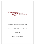
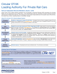
6. Electrical Connector
Trailers and chassis shall be equipped with a conventional (7 conductor) electrical connector
socket, wired and installed as shown in Figure 1. The voltage marking shall be shown adjacent to
the socket in not less than 1-inch-high letters, only if it is different than 12 volts.
1/1/2014
–1–
AAR Intermodal Interchange Rules
SECTION A
GENERAL CONDITIONS
Figure 1 Connector Socket
Conductor Number
Wire Color
Lamp and Signal Circuits
1
White
Ground return to towing vehicle
2
Black
DOT-required marker and clearance lamps
3
Yellow
Left-hand directional signal
4
Red
5
Green
Right-hand directional signal
6
Brown
Tail lamps, three-bar marker lamps, and clearance or
marker lamps other than DOT-required
7
Blue
Stop lamps and anti-lock devices
Anti-lock brake system.
The standard receptacle shall be constructed as a flush-mounted unit and provided with a
cover, and shall be mechanically attached to the connector socket or external housing.
Cover shall make the connector socket weather tight when the cable plug is not inserted in
the socket.
7. Lights
a. Trailers and chassis shall be equipped with properly operating stop lights, tail lights, flashing
turn signals, clearance and marker lights, reflectors, and other parts and accessories as
required by governmental regulatory agencies.
b. Units shall be equipped with conspicuity tape as required by governmental regulatory
agencies. Chassis also shall have conspicuity tape applied to the front bolster.
–2–
1/1/2014
AAR Intermodal Interchange Rules
GENERAL CONDITIONS
SECTION A
8. Tank Containers
Tank containers must comply with applicable Department of Transportation regulations.
a. Compliance Certification
TOFC loading of tank containers must be on certified AAR M-931 Appendix G chassis.
b. Loading Conditions
Tank containers must comply with applicable DOT regulations, including 49 CFR 174, for
interchange movement under these rules. Additionally, on conventional single-unit COFC cars,
end-of-car cushioning and positive lock securement devices meeting the requirements of AAR
Specification M-952, latest revision, are required. Cushioning protection is not required on
multi-unit spine cars and other slackless intermodal equipment. Tank containers may be moved
in the well of single- or multi-unit double-stack cars, but no other container may be loaded above
the tank container placarded “Hazmat.” In single- or multi-unit double-stack cars, neither
cushioning nor positive lock securement is required.
c. Tank Data Plate
Tank data plate(s) must be affixed to the tank or frame.
d. Tank and Safety Relief Valve
Tank and safety relief valve, if installed, must have a retest interval no greater than 5 years.
Retest and test due dates must be marked or stenciled on the tank or on an appropriate plate.
e. Inspection
Tank containers must be inspected for leakage before acceptance for shipment.
9. Tank Trailers (“Cargo Tanks”) Carrying Materials
Tank trailers carrying hazardous materials are prohibited in TOFC service, except AAR M-931
specification tank trailers as may be allowed by Department of Transportation regulation.
10. Document Holder
A waterproof container for necessary papers and documents to accompany the trailer shall be
attached to the exterior of the trailer, on the nose end, as near the side and bottom of the trailer as
practical. The same type container shall be attached to the main rail of the chassis near the VIN
plate.
11. Tires
Trailers and chassis shall be equipped with tires conforming to requirements of Section B of these
rules.
12. Landing Gear
Trailers and chassis shall be equipped with landing gear conforming to requirements of Section C of
these rules.
1/1/2014
–3–
AAR Intermodal Interchange Rules
SECTION A
GENERAL CONDITIONS
13. Licensing
Trailers and chassis shall be equipped with valid license plates of the state of registry. It is the
responsibility of the originating carrier to ensure that trailers and chassis are properly licensed and
registered.
14. Interchange Placement
A unit offered in interchange shall be considered as accepted by the receiving carrier.
a. Rail Interchange
When the car with the unit is placed on a track agreed upon and designated as the interchange
track for such delivery, and is accompanied or preceded by proper data for forwarding and to
ensure delivery.
b. Rubber Interchange
When a trailer that is interchanged by street or highway is placed in a yard or at a point agreed
upon and designated as the interchange point for such delivery, accompanied or preceded by
proper data for forwarding and to ensure delivery, and unit inspection form or recorded image
has been completed.
15. Defective Units
A unit offered in interchange with defects as defined in Section F may be rejected by the receiving
carrier.
16. Flat Rack Containers
The following interchange requirements apply to AAR-approved versions (versions 6.2 and 7.1) of
Raildecks flat rack containers:
a. Concentrated Loads
Raildecks version 6.2 or 7.1 are limited to hauling concentrated loads that do not exceed
46,000 lb. Concentrated loads are defined as the total load weight acting in 4 linear feet or less
of the deck. Concentrated loads shall be placed in the bottom position of a double-stack well
car that is capable of handling 20 ft containers.
b. Well Placement
Loaded Raildecks must be placed in the bottom position of all well cars. Empty Raildecks can
be placed in top position in double-stack or bottom position in single-stack configuration as long
as the center of gravity is taken into account.
c. Loaded Stacking Configuration
The gross weight of the top container in any double-stack configuration cannot exceed the
gross weight of the bottom container. Exception: CN will only accept in single-stack
configuration.
–4–
1/1/2014
AAR Intermodal Interchange Rules
GENERAL CONDITIONS
SECTION A
d. Steel Coils
Steel coils are permitted in interchange provided that the originating and receiving railroads
have both approved the shipper.
e. Load Securement
All load securement meets or exceeds securement standards set forth by the AAR Open Top
Loading Rules (OTLR) committee.
f. Gross Weight
Gross weight (Net + Tare) of the Raildeck container and lading shall not exceed 67,200 lb.
g. Hazmat Restrictions
No placarded HAZMAT containers may be loaded in the same well with the Raildeck container
or in any adjacent well.
h. Empty Collapsed Movement Requirements
Empty bundled Raildecks stacked three or four high with arms collapsed are acceptable in
interchange.
17. Gasoline/LPG Refrigeration Units
Trailers or containers using gasoline or liquefied petroleum gas to operate refrigeration units must
be permanently stenciled, “Gasoline Driven Refrigeration Unit” or “Liquefied Petroleum Driven
Refrigeration Unit” in accordance with Section D, Rule 55 of these rules.
18. Portable Heater Units
Trailer/container equipment with portable heating units may be refused in interchange service.
19. Equipment Registration and Reporting
a. Equipment Initial/Number
Each unit shall have an assigned reporting mark of its owner or lessee and the number of the
unit appearing thereon, as provided in Rule 173.
b. TRAIN II and UMLER Reporting
Effective July 1, 1999, to facilitate tracking and accounting of equipment, equipment owners
shall register all trailers, containers, and chassis in the Universal Machine Language Equipment
Register (UMLER), as specified in the UMLER Specification Manual.
Effective July 1, 1999, to facilitate tracking and accounting of equipment, handling lines shall
report all trailer, container, and chassis interchanges and movements to TRAIN II, as specified
in the TRAIN II User’s Manual.
Where the term “unit” appears in these rules, it includes all railroad-owned and private
equipment that is used in TOFC/COFC service contained in Rule 159.
1/1/2014
–5–
AAR Intermodal Interchange Rules
SECTION A
GENERAL CONDITIONS
20. Kingpin Wear Limits
Trailers and chassis offered in interchange may be refused by the receiving carrier if wear limits
exceed those prescribed by SAE J-2228, latest revision [see Appendix B, Section B11(a].
21. to 25. Vacant
–6–
1/1/2014
AAR Intermodal Interchange Rules
TIRES AND TUBES
SECTION B
SECTION B
TIRES AND TUBES
26. Conditions at Time of Acceptance and in Interchange
The following are conditions at time of acceptance and in interchange.
a. Presence of Tires and Wheel Lugs
Tires and all wheel lugs must be in place on all wheels in service.
b. Suitability of Tires and Rims
Tires and rims must be in suitable condition for safe movement to final destination and must
conform to requirements of governmental regulatory agencies.
c. Tire Markings
At the time of inspection, the company tire brand, if any, or manufacturer’s serial number and
tire size must be in evidence.
d. Lack of Foreign Objects
Tires must be free of visible foreign objects such as nails, etc., imbedded in or protruding from
tire, as well as defects listed in Rule 27.
e. Inflation and Mating
Tires must be properly inflated and mated by physical size on the same axle.
27. Maintenance, Repair, and Replacement
a. Trailer or Chassis Owner Responsibility
Repairs, renewals, or replacement of tires and/or tubes shall be at the expense of the trailer or
chassis owner, except as otherwise provided in Section F. The trailer or chassis owner shall be
responsible for renewal of tires and tubes when necessary, due to the following causes:
(1) Tread depth 2/32 inch or less. Measurement must be made in tread grooves only, not
to include tire tread tie bars.
(2) Separation of tread
(3) Visible blisters or knots
(4) Worn out, deteriorated tube
(5) Pulled valve stem, cut tube, when not associated with Section F damage to tire
1/1/2014
–7–
AAR Intermodal Interchange Rules
SECTION B
TIRES AND TUBES
b. Handling Line Responsibility
(1) Maintenance
The carrier in possession of a trailer or chassis in interchange service shall provide
maintenance to tires and tubes, including proper inflation, the repair of flat tires, pulled valve
stems, etc., subject to provisions of other rules with regard to charges. When a tire and/or
tube is repaired or replaced, the carrier in possession must inflate all tires on the trailer or
chassis to the manufacturer’s recommended psi. Ensure all hoses are reconnected to
automatic tire inflation systems. Valve caps must be installed.
(2) Unserviceable Tires
When an unserviceable tire is replaced by other than the owner, it must be with a new tire
or newly recapped tire meeting the Minimum Standard for Retreading and Repairing Bias
Ply and Radial Tires, as shown in Appendix B, Section B14 to justify charge to the owner.
The application of used tires and/or tubes by the handling carrier is prohibited and is
considered wrong repair, and no charge can be assessed the trailer or chassis owner.
(3) Rims
Exchanging of rims is prohibited, unless necessary due to an unserviceable rim. When
replacing a rim, a rim of the same type and size must be used, e.g., 20 inch tube type with
a 20 inch tube type; 22 inch tubeless with a 22 inch tubeless.
(4) Serviceable Tubes
When a tire is replaced, a serviceable tube and flap that is removed must be reapplied.
(5) Unserviceable Tubes
When an unserviceable tube is replaced by other than the owner, the tube must be replaced
with a new tube to justify charge. The unit repair billing form must show the size, the
location on/off, and the reason for replacement.
(6) Booting, Sectioning, or Vulcanizing
Structural repairs to tires on foreign trailers or chassis by booting, sectioning, or vulcanizing
by the handling carrier is prohibited and is considered wrong repair, and no charge can be
assessed the trailer or chassis owner.
(7) Exchanging of Tires
Exchanging or swapping tires due to a flat tire condition is prohibited.
(8) Multiple Renewals and Replacement at Terminals and by Contracted Vendors
Renewals and replacements at terminals and by contracted vendors of two or more tires
on the same unit due to the causes listed as Trailer or Chassis Owner Responsibility
(Rule 27a) require fax or electronic notification to the owner within 2 business days from
the time of repair, if the owner has provided notification information for the listing published
by the AAR. Lack of receipt of required notification by an owner is not in itself justification
for not paying a repair bill.
–8–
1/1/2014
AAR Intermodal Interchange Rules
TIRES AND TUBES
SECTION B
c. Repair, Renewal, and Replacement Procedures
(1) Tire Repair Billing Form
The Tire Repair Billing Form to the owner must show the tire size and manufacturer’s DOT
tire identification number for each new tire applied or the recapper’s DOT tire identification
number for each recapped tire applied to justify charge. The same information must also
be shown for each tire removed, if available. Billing must also show tire location and the
reason for replacement to justify charge. All information pertaining to DOT identification
codes, both on new or recap tires, must follow federal regulations, in accordance with Tire
Identification and Recordkeeping Regulation, 49 CFR Part 574 (36 F.R. 1196).
(2) Inspection and Collection of Unserviceable Tires
The inspection and collection of unserviceable tire(s) shall be a matter of mutual agreement
between involved parties as to procedures.
(3) Retention Period
When tires are removed from a trailer or chassis at an intermodal facility or at an outside
repair facility authorized by the railroad, the tire must be maintained at the facility for at least
7 days or as otherwise agreed. Tire(s) must be marked identifying the trailer or chassis
initial and number, date, wheel position, and circle defect. The Why Made Code and tread
depth must also be indicated.
28. to 40. Vacant
1/1/2014
–9–
AAR Intermodal Interchange Rules
SECTION B
TIRES AND TUBES
THIS PAGE LEFT BLANK INTENTIONALLY
–10–
1/1/2014
AAR Intermodal Interchange Rules
LANDING GEARS
SECTION C
SECTION C
LANDING GEARS
41. Conditions at Time of Acceptance and in Interchange
The following are conditions at time of acceptance and in interchange:
a. Load Support
The landing gear must be in suitable condition to properly support the trailer or chassis load.
b. Condition and Securement
The landing gear must be properly secured to trailer or chassis, complete as to component
parts, and in satisfactory operating condition.
c. Clearances
The landing gear of the trailer or chassis while loaded on a railcar must clear the car floor and
other fixed obstructions at all times by not less than 2 inches, to prevent damage.
42. Maintenance and Operation
a. Maintenance, Repairs, and Lubrication
The carrier in possession of the trailer or chassis shall provide good maintenance to the landing
gear, including minor repairs and lubrication.
b. Raising Landing Gear
The landing gear must be raised sufficiently above the car floor or ground before moving
the trailer or chassis, to prevent damage.
c. Lowering Landing Gear
The trailer or chassis landing gear must be properly lowered before disconnecting the tractor
from the trailer or chassis.
43. to 54. Vacant
1/1/2014
–11–
AAR Intermodal Interchange Rules
SECTION C
LANDING GEARS
THIS PAGE LEFT BLANK INTENTIONALLY
–12–
1/1/2014
AAR Intermodal Interchange Rules
REFRIGERATION AND HEATING
SECTION D
SECTION D
REFRIGERATION AND HEATING
55. Conditions at Time of Acceptance and in Interchange for Mechanical Units
The following are conditions at time of acceptance and in interchange:
a. Stenciling/Fuel type
Trailers or containers equipped with mechanical units shall be stenciled in letters not less than
1 inch high to indicate the type of fuel used to drive the unit and the capacity of the fuel tank.
Stenciling shall be located adjacent to the unit or fuel tank filler cap. The type of fuel used for
operating the mechanical unit is subject to the restrictions provided in Section A, Rule 17.
b. Satisfactory Operating Condition
At the time of interchange of a loaded trailer or container under heat or refrigeration, the
mechanical unit shall be in satisfactory operating condition. Where evidence indicates a
defective mechanical unit or improper inside air temperature, the trailer or container may be
refused in interchange.
c. Sufficient Oil and fuel
At the time of interchange of a loaded trailer or container under heat or refrigeration, the
mechanical unit shall have sufficient oil and fuel to ensure 24 hours’ continuous operation.
56. Vacant
57. Maintenance
The carrier in possession of the trailer or container shall provide proper maintenance to the heating
and/or refrigeration unit, including any immediate repair necessary to maintain lading protection.
The cost of repairs made as a result of such maintenance may be billed against the owner, except
that fuel applied is at no expense to the owner. Where Division Sheet or contracts provide
otherwise, the provisions of this rule do not apply.
58. Portable Units
Trailer/container equipment with portable units may be refused in interchange service.
59. to 70. Vacant
1/1/2014
–13–
AAR Intermodal Interchange Rules
SECTION D
REFRIGERATION AND HEATING
THIS PAGE LEFT BLANK INTENTIONALLY
–14–
1/1/2014
AAR Intermodal Interchange Rules
ACCESSORIES AND SPECIAL EQUIPMENT
SECTION E
SECTION E
ACCESSORIES AND SPECIAL EQUIPMENT
71. Removable Items/Stenciling
The name and number of removable items accompanying open top, platform, or flatbed trailers
must be stenciled in not less than 1 inch figures in a suitable location of the trailer (preferably the
front portion of the bulkhead).
Removable items include:
a. Chains, binders, cables and tie-down devices
b. Tarpaulins, including securements
c. Tarpaulin bows
d. Rear header bar (high-side open top)
e. Bulkhead
72. Delivering Carrier Responsibility
The delivering carrier shall be responsible for any removable items listed in Rule 71, and so
stenciled on trailer, that are missing when the trailer is offered in interchange.
73. Handling Carrier Responsibility
a. Securement of Equipment
The proper replacement and securement on the trailer of tarpaulins, tarpaulin bows, rear header
bar, side sections, end gates, etc., that were removed to facilitate loading or unloading is the
responsibility of the carrier in possession of the trailer.
b. Tarpaulins and Bows—Loaded Trailers
When a loaded open top trailer is offered in interchange and is equipped with tarpaulins and
bows, the tarpaulin and bows must be in their proper position with the tarpaulin spread and
secured.
In the event the lading is of such nature that the tarpaulin and bows cannot be applied, they
must be placed in the proper storage receptacle where the trailer is so equipped or accompany
the load, if possible. If the equipment cannot be forwarded in either manner, provision should
be made to ship same to the trailer owner, properly identified, at the expense of the carrier
returning the equipment.
1/1/2014
–15–
AAR Intermodal Interchange Rules
SECTION E
ACCESSORIES AND SPECIAL EQUIPMENT
c. Equipment—Empty Trailers
When an empty open top or platform type trailer is offered in interchange and is equipped with
tarpaulin and bows, side and end gates, etc., the tarpaulin and bows, side and end gates, etc.,
must be in proper place and secured on the trailer or placed in the proper storage receptacle
(where the trailer is so equipped) or be secured to the headboard or deck of the trailer.
When side and end gates are in an upright position on the trailer, the bows must also be in
proper position, and the tarpaulin must be properly stored.
Chains, binders, cables, and tie-downs devices must not be laced or allowed to hang over rub
rails of flatbed trailers.
74. to 80. Vacant
–16–
1/1/2014
AAR Intermodal Interchange Rules
HANDLING CARRIER RESPONSIBILITY
SECTION F
SECTION F
HANDLING CARRIER RESPONSIBILITY
81. Damage—By Causes
Handling carriers are responsible for damage caused by:
a. Accident of any type, at any time, on or off a railcar
b. Storm or flood
c. Explosion
d. Unconcealed fire and inside or concealed fire, when handling line has knowledge of same,
while unit is in its possession
e. Failure to properly handle unit on or off car
f. Failure to properly close and secure doors
g. Contamination by loading with contaminating commodities such as:
(1) Animal products, including hides, pelts or skins; glue stock, manure, or fertilizing
compounds with contaminating odor; meat refuse, offal, tankage, or waste from
slaughtered animals; bones or horns with contaminating odor; dried blood; tallow
(2) Copra
(3) Fish scrap or fish meal
(4) Shellfish in bulk
(5) Shells (clam, mussel, or oyster) in raw state with contaminating odor
(6) Asphalt (asphaltum), natural or asphalt compounds, by-product or petroleum
(7) Creosote or creosoted materials
(8) Lamp black, carbon black (all types), graphite (black lead), or plumbago
(9) Poisonous chemicals or compounds in containers or bulk
(10) Scrap batteries and vehicle components, including loose or baled scrap metal that
leaks oil and grease, such as, but not limited to, axles, differentials, engine blocks, and
transmissions
(11) Loose metal shreddings or shavings not in bales or containers
(12) Bulk municipal waste
(13) Bakery waste
1/1/2014
–17–
AAR Intermodal Interchange Rules
SECTION F
HANDLING CARRIER RESPONSIBILITY
h. Repair and servicing to brakes and brake system components due to accumulation of ice
and snow
82. Damage—Evidential
Handling carriers are responsible for damage as follows:
a. Metal door, gate, sheet, post, crossmember, brace, or support cut or torn through thickness
of metal, including such cuts or tears covered by tape, caulk, and/or tar
b. Metal door, gate, sheet, post, crossmember, brace, or support bent, where proper operation
or function of unit is impaired, except when caused by deterioration due to corrosion or
decay
c. Clean Interior
d. DOT Under Ride Guard missing or bent/cut per Appendix B, Section B15
e. Tire sidewall cut/punctured through one or more plies of fabric
f. Tire shoulder and/or tread cut/punctured through one or more plies of fabric, when such injury
is larger than 1/4 inch. When the tire shoulder and/or tread is punctured through the tire,
causing a hole 1/4 inch in diameter or less, the injury must be patched prior to reuse.
g. Damage to tires and tubes as a result of being slid flat. Any tire is considered to be “slid flat”
if a flat spot occurs and removes 4/32 inches of tread or rubber (when compared to the remaining tread). It is not necessary for the tire to have a loss of air.
h. Damage to tires and tubes as a result of being run flat. To prevent run-flat damage, tires
should be inflated as per Appendix B, Section B14.
83. Losses
Handling carriers are responsible for loss as follows:
a. Theft of trailer, container, chassis, or bogie, or known theft of parts thereof
b. Door or gate missing
c. Removable side or section missing
d. Missing tire, tube, or rim
e. Missing assigned equipment, as outlined in Rule 71, that accompanied trailer at time of
interchange
f. Missing component parts essential for the operation of mechanical units for refrigeration or
heating.
–18–
1/1/2014
AAR Intermodal Interchange Rules
HANDLING CARRIER RESPONSIBILITY
SECTION F
84. Contamination Commodities
a. Loading Restriction
Trailers or containers must not be loaded with contaminating commodities unless the trailer or
container is stenciled by the owner “Contaminate Loading Only” on the front of the vehicle in not
less than 4 inch letters and is identified in the Official Intermodal Equipment Register, or as
otherwise specifically authorized by owner.
b. Reporting Contaminating Loadings
Where the handling carrier is not responsible for a contaminating loading, it shall furnish
information on the unit inspection form to indicate the originating carrier, who shall be
responsible to the owner for reconditioning of the trailer or container.
85. Temporary Repairs
Handling carriers shall be responsible for correction of temporary repairs as outlined in Rule 101b.
86. Damage by Non-AAR Member
a. Railroad-Owned or Leased Units
When a railroad-owned or leased unit is damaged or destroyed while in the possession of a
non-AAR member to the Intermodal Interchange Rules, the AAR member delivering the unit to
such non-AAR member shall be responsible to the owner for damage to or destruction of the
unit while in the possession of the non-AAR member.
b. Non-Railroad-Owned or Leased Units
When a non-railroad-owned or leased unit is damaged or destroyed while in the possession of
a non-AAR member to the Intermodal Interchange Rules, responsibility and settlement for
damage or destruction will be in accordance with individual contract.
87. Vacant
1/1/2014
–19–
AAR Intermodal Interchange Rules
SECTION F
HANDLING CARRIER RESPONSIBILITY
THIS PAGE LEFT BLANK INTENTIONALLY
–20–
1/1/2014
AAR Intermodal Interchange Rules
ORDINARY MAINTENANCE
SECTION G
SECTION G
ORDINARY MAINTENANCE
88. Owner Responsibility
Repairs, renewals, or replacement of the following components shall be at the expense of the unit
owner, except where directly associated with a component with Section F damage:
a. Dolly wheels, sand shoes, and/or axles
b. Manifest box
c. Door locking bar handles
d. Door tie-backs
e. Lights
f. Initial and number markings, including sign boards, and conspicuity treatment consistent with
regulatory agencies’ rulemaking and mandated for units manufactured after December 1,
1993
g. Mud flaps and brackets
h. Broken batteries
i. Caulking and sealing of seams and old patches, subject to provisions of Rule 100
j. Container securement device handles and safety latches
k. Refrigeration cabinet doors and battery box covers
l. Axle, axle spindle, hub assembly, lubrication, and failure due to insufficient lubrication
m. Replacement or repair of glad hands
n. Interior lining, including posts
o. Interior landing gear components
p. Closed trailer or container roof bows
q. Floor or decking
r. Sliding tandem removable locking bars
s. Component securements, including bolts, rivets, welds
1/1/2014
–21–
AAR Intermodal Interchange Rules
SECTION G
ORDINARY MAINTENANCE
t. Repairs to brakes and components, except repair and servicing due to accumulation of ice
and snow. Brake adjustment on trailers or chassis not equipped with automatic slack
adjusters may be performed only upon the driver’s request, in which case the driver’s
signature is required and must be maintained on file.
u. Damage to the first three crossmembers behind the grid section of trailers not originally
equipped with grid extension plate
v. Trailer/chassis locking assemblies
w. Lift pads
x. Landing gear operating cross shaft
y. Tank container components
z. Replacement of dolly crank handle
aa. Cleaning and adjustment of electrical connector socket
ab. Federal Motor Carrier Safety Administration (FMCSA) Periodic Inspection (PI) and
Certification and other regulatory standards
ac. Renewals or replacements, including application of vehicle license plates and/or
registration papers
ad. Roll-up doors
ae. Side doors
89. to 94. Vacant
–22–
1/1/2014
AAR Intermodal Interchange Rules
REPAIRS AND BILLING
SECTION H
SECTION H
REPAIRS AND BILLING
95. Detailed Procedures
For more detailed procedures on repairs and billing, refer to Appendix A.
96. Repairs Exceeding $450
When the estimated cost of repairs exceeds $450 or other amount specified by the owner,
exclusive of tires and refrigeration unit, repairs shall be handled under the provisions of Section L,
Rule 156 or Section M, Rule 165 and Rule 166.
97. Handling Line Responsibility
When a unit damaged in excess of $450 or other amount specified by owner is returned to its owner
for repairs, the carrier responsible for the damage will be responsible for those items as listed on
Form J-2 or recorded image.
98. Repair Cost Limit
In no case shall the cost of repairs to a unit exceed its depreciated value less salvage, except as
provided in agreements between carriers and handling lines.
99. Standards for Repair
When repairs are made to a unit, the owner’s standard must be maintained, and material applied
must be of similar quality and type as material removed. Repairs are subject to the procedures of
Appendix B. Repairs, when completed, are subject to acceptance by the unit owner. If the owner’s
standard(s) for the applicable repair or replacement of specific component(s) is stenciled on the
unit, such standard must be followed.
100. Safety—Conditioning for Loading
Any unit that requires repairs to render it safe for handling or to condition it for loading, may be
repaired subject to provisions of these Intermodal Interchange Rules. However, if repairs are made
in order to condition the unit for loading, the repairing company must load the unit before releasing
or interchanging it in order to justify the bill for repairs.
101. Repairs Requiring Authorization
a. All repairs to the following trailer, container, and/or chassis components must be performed
only by authorization and at the direction of the owner:
(1) Kingpin and/or upper coupler assembly
(2) Exterior fiberglass sidewalls
(3) Refrigerated trailer or refrigerated container end doors
1/1/2014
–23–
AAR Intermodal Interchange Rules
SECTION H
REPAIRS AND BILLING
(4) Brake adjustment on trailers or chassis equipped with automatic slack adjusters,
except as may be required by government regulation. Brake adjustment on trailers or
chassis not so equipped may be performed only upon the driver’s request, in which
case the driver’s signature is required and must be maintained on file.
(5) The repair or replacement of Under Ride Guards (ICC Bumpers) that are certified in
accordance with FMVSS 223 and FMVSS 224 effective January 26, 1998
b. Units identified with improper repair(s) by handling line should be handled as follows:
If the estimated cost of correcting improper repair(s) exceeds $450, the cost shall be subject to
acceptance by the equipment owner. Photos of improperly repaired component(s) must be
furnished with authorization requests. Should it be discovered that improper repairs were
performed while equipment was in possession of a handling line, the equipment owner may
re-bill that handling line providing adequate support is furnished indicating that handling line’s
liability.
102. Citations
The unit owner or lessor shall make full payment on the citation. The rail carrier in possession of the
rail-controlled unit at the time of the citation may be rebilled by the unit owner or lessee.
103. to 109. Vacant
–24–
1/1/2014
AAR Intermodal Interchange Rules
ADJUSTMENT OR TRANSFER
SECTION I
SECTION I
AUTHORITY FOR ADJUSTMENT OR TRANSFER OF INTERMODAL EQUIPMENT AND/OR INTERMODAL LADING
110. Delivering Carrier Responsibility
a. Compliance with Loading Rules
Lading shall be properly distributed, secured, and blocked, and in compliance with the AAR
Intermodal Loading Guide for Products in Closed Trailers and Containers, and the AAR
Mechanical Section 7 Rules Governing the Loading of Commodities on Open Top Trailers to Be
Handled in Trailer/Container-on-Flat-Car (TOFC/COFC) Service (which includes flat bed and
platform equipment).
b. Adjustment/Transfer of Units and Lading
Adjustment or transfer of units and/or lading shall be the responsibility of the delivering carrier
as follows:
(1) Shifted Contents/Improper Loading
When a trailer or container is delivered by rail, street, or highway for interchange and
requires adjustment of lading due to shifted contents or improper loading.
(2) Defective Trailer or Container
When requiring transfer or adjustment of lading due to a defective trailer or container that
cannot be readily repaired.
(3) Defective Car/Attachment
When requiring transfer of unit due to a defective carrying car or attachment that cannot be
readily repaired.
111. Originating Carrier Responsibility
The following shall be the responsibility of originating carrier:
a. Transfer—Clearance Violation
Transfer due to clearance violation as outlined in Section A, Rule 4.
b. Transfer and Delivery—Overload
Transfer due to overload, if in violation of Section A, Rule 5. If a portion of the load must be
transferred to another trailer or container, all costs of delivering the second trailer shall be the
responsibility of originating carrier.
c. Damage—Overload
Damage to trailer or container due to overloading, if in violation of Section A, Rule 5.
112. to 119. Vacant
1/1/2014
–25–
AAR Intermodal Interchange Rules
SECTION I
ADJUSTMENT OR TRANSFER
THIS PAGE LEFT BLANK INTENTIONALLY
–26–
1/1/2014
AAR Intermodal Interchange Rules
FORMS AND REPORTS
SECTION J
SECTION J
FORMS AND REPORTS
120. General Instructions
Forms and/or reports as required by these rules shall be in accord with the following provisions as
to form, use, and manner of preparation. Any suitable equivalent form, report, or electronic image
may be used, provided it embodies the minimum information required.
121. Unit Interchange and Safety Inspection Report, Form J-1
Form J-1, equivalent, or recorded image shall be prepared by an authorized representative each
time a unit is offered for interchange movement by street or highway. (See Figure 2.)
At locations with electronic camera technology that captures images of equipment and damage, it
shall not be a requirement to provide notification of damage at time of interchange. Any invoice for
damage to the equipment shall be accompanied by an electronic picture of the actual interchange
of the unit showing damage with a date and time stamp.
122. Unit Damage Responsibility Report, Form J-2
a. Preparation and Use of Form
(1) Damage Form and Distribution
Form J-2 (see Figure 3) shall be prepared by an authorized representative of the handling
carrier to document damage or loss for which the handling carrier is responsible. The form
shall be prepared at the place of interchange and then accompany the bill for repairs to the
carrier responsible.
One copy shall be forwarded to a processor for electronic distribution and billing. One copy
shall be retained by the issuing party. Copies shall be forwarded within 48 hours from the
time of preparation. The processor will electronically distribute copies of Form J-2 to
delivering and receiving parties.
(2) Recorded Image
A recorded image of the damage, taken at the time and place of interchange, may be used
in lieu of a written Form J-2. This recorded image may be used to document damage or
loss for which the handling carrier is responsible.
(3) Interchange with Unrepaired Damage Not Covered by Form
In the event a unit is offered in interchange with unrepaired damage or loss for which the
delivering carrier is responsible and that is not covered by a copy of this form, the receiving
carrier shall obtain from the delivering carrier a copy of Form J-2 described in Rule 122a or
a recorded image of the damage.
1/1/2014
–27–
AAR Intermodal Interchange Rules
SECTION J
FORMS AND REPORTS
(4) Time Limit for Repair
Damage covered by this report must be repaired within 90 days from date of Form J-2;
facilities equipped with automatic gates systems must have damages repaired within 45
days of interchange to justify bill for repairs.
(5) Associated Damage
When performing repairs to damaged items noted on Form J-2, it is allowable to repair and
bill for the associated damaged item(s) if necessary for a proper repair. Associated items
must be indicated by why made code 01 on repair bill.
If the estimate of associated repairs exceeds $250 or another amount specified by the
responsible party, endorsement by the responsible party must be secured prior to repairs
being made.
Associated damage is damage to adjoining components occurring in the same
incident.
b. Exception to Form
After issuance, this report must not be altered and shall be binding. It is the responsibility the
party taking exception to Form J-2 under provisions of Rule 122a(4), Time Limit for Repair, to
provide equipment movement information to the billing party to substantiate exception.
c. Provision of Rebill Authority
When a unit is returned to its owner, the delivering carrier shall provide the owner with rebill
authority within 48 hours, excluding Saturdays, Sundays, and holidays, from written or
electronic notification by the owner to the delivering carrier of damages, unless in dispute.
Failure to provide the owner with rebill endorsement authority, unless in dispute, shall constitute
a valid acceptance by the delivering carrier of damages as specified on Form J-2 or its
equivalent.
123. Form J-3—Authority for Transfer or Adjustment of Intermodal Equipment or
Intermodal Lading
a. Preparation and Use of Form
Form J-3 (see Figure 5) or electronic equivalent shall be prepared in triplicate by an authorized
representative of the handling carrier when it is necessary to transfer or adjust lading in a trailer,
container, or a trailer on a car, and it is the responsibility of the carrier as set forth in Section I,
“Authority for Adjustment or Transfer of Intermodal Equipment and/or Intermodal Lading,” of
these rules.
The original form shall accompany the bill, one copy shall be forwarded to the carrier
responsible, and one copy shall be retained by the handling carrier.
b. Expense Responsibility
The expense of adjustment or transfer of unit or lading shall be handled by contract.
–28–
1/1/2014
AAR Intermodal Interchange Rules
FORMS AND REPORTS
SECTION J
124. Vacant
125. Authority for Counterbilling, Form J-5
a. Purpose
Form J-5, Counterbilling Authority, shall be used for monetary adjustment between the parties
concerned. (See Figure 7)
b. Completion of Form
All details in Counterbilling Authority, Form J-5, must be properly filled out.
126. FMCSA-PI Certification, Form J-6
Form J-6 (see Figure 8) shall be prepared by a certified FMCSA-PI inspector as follows: the
original or an electronic version thereof shall accompany the bill, one copy shall be placed on the
trailer or chassis, one copy shall be forwarded to the owner within 30 days after certification, and
one copy shall be for the inspector.
1/1/2014
–29–
AAR Intermodal Interchange Rules
SECTION J
FORMS AND REPORTS
127. FMCSA-PI Certification Acknowledgment, Form J-7
a. Form J-7 (decal) (see Figure 9) shall be applied to the lower right front center (nose) of the
trailer (curb side).
b. Form J-7 (decal) (see Figure 9) shall be applied on chassis on the left side main rail next to
the document holder (viewable when loaded). It shall be at least 6 in. × 4 ½ in. in size.
The decal shall have black letters on a white background. It shall be at least 8½ in. × 8½ in. in size.
Its letters shall have the following minimum dimensions:
“AAR FORM J-7”: ½ in.
“FMCSA – PI,” “MONTH, YEAR”: 1 in.
Other letters: 5/16 in.
128. AAR Flat File Format
The “J File” allows for the electronic exchange of damage data. Refer to Appendix D for structure
and sample.
129. to 135. Vacant
–30–
1/1/2014
Figure 2 Form J-1—Unit Interchange and Safety Inspection Form
Form J-1
)RUP-
UNIT INTERCHANGE AND SAFETY INSPECTION FORM
Initial__________________ Number________________
Van
Container
Chassis
Station____________________________________ Date____________________ Time____________
Delivered By_______________________________ Received By_______________________________
Seal No.__________________________________ License No.________________________________
Origin_______________________ Route_______________________ Destination_________________
MARK CLEARLY ALL DAMAGE BY INSPECTION SYMBOL “C” CUT, “B” BENT, “K” BROKEN, “M” MISSING
EXPLAIN DEFECTS:
TIRE CONDITIONS: “C” CUT, “SF” SLID FLAT, “RF” RUN FLAT, “M” MISSING
ROF
LOF
RIF
LIF
ROC
LOC
RIC
LIC
ROQ
LOQ
RIQ
LIQ
RIR
LIR
ROR
LOR
INSPECTED AND EXCEPTIONS NOTED
DELIVERED BY_________________________________ RECEIVED BY_________________________________
INSPECTED BY_________________________________ INSPECTED BY________________________________
Figure 3 Form J-2—Intermodal Equipment Damage Report
Form J-2
No.
,17(502'$/(48,30(17'$0$*()250-
Equipment Initials____________________ Equipment Number__________________
Delivered by______________________
via
Street
Rail
Van
Container
Chassis
to___________________
at (Station)_________________________________________ on (Date)_____________________________
Responsibility. ___________________
Railcar: Initials/No.________________________
BENT
CUT
&251(5&$36
LEFT
BRO.
522)
RIGHT
CUT
QTY
FRONT
BENT
5$',863$1(/
BENT
&251(53267
R-
CUT
QTY
DIMENSONS
CUT
BENT
FRONT
L-
BENT
REAR DIMENSION
R-
BENT
BRO
L-
BENT
BRO
CUT
BENT
BENT
DIMENSIONS
LEFT
QTY
BENT
CUT
BRO
DIMENSIONS
QTY
(;76,'(32676
BENT
CUT
BENT
CUT
BRO
(;76,'(32676
CUT
CUT
QUANTITY
FRONT
BRO.
LS
BENT
CUT
RS DIMENSION
5,06
RS
BENT
5($56,//
BENT
CUT
BRO
BENT
FRONT
CUT
BRO.
BENT
REAR
CUT
BRO.
BENT
FRONT DIMENSION
&52660(0%(56
BENT
'2253267
LR
RR
BENT
CUT
LEGS
REAR DIMENSION
%277206,'(5$,/
BENT
CUT
BRO.
%277206,'(5$,/
BENT
CUT
BRO.
CUT
BAY
TANDEM
&5266&+$11(/833(5
BRO
QUANTITY
BRO
7811(/5$,/6
DIMENSIONS
LS
REAR DIMENSION
MS
TUBELESS
LOCATION(S)
BRO
BENT
FRONT DIMENSION
CUT
TUBE
BRO
DIMENSIONS
QUANTITY
67$&.,1*3267
REAR
CUT
LS DIMENSION
&5$1.6+$)7
67$&.,1*3267
RS
BENT
BRO
02817,1*%5$&.(7
:,1*3/$7(
DIMENSIONS
BENT
0$,1)5$0(5$,/
5($5+($'(5
CUT
,176,'(32676
RIGHT
BRO.
CUT
LS
&5266%5$&(/2:(5
DIMENSIONS
,176,'(32676
BENT
BRO
QUANTITY
L-_____, R-_____
BENT
QTY
CUT
LS-_____, RS-_____
BRO.
DIMENSIONS
BENT
RS DIMENSION
&+$66,6
&52660(0%(56
QUANTITY
+,1*(6
6,'(3$1(/6
CUT
LS DIMENSION
RS
BRO
BENT
QUANTITY
6,'(3$1(/6
LS
',$*21$/%5$&(6
BENT
QTY
CUT
L-_____, R-_____
RIGHT
7236,'(5$,/
BRO.
NON-GEAR
BRO
QUANTITY
CUT
GEAR
BENT
/2&.52'6
BENT
RS
BENT
/$1',1*/(*6
'2256
DIMENSIONS
6/,'(55$,/
LS
/(*6
5($5
%8/.+($'
7236,'(5$,/
REAR
CUT
FRONT DIMENSION
DIMENSION
)52176,//
6,'(6
FRONT
BENT
REAR DIMENSION
DIMENSIONS
LEFT
BRO.
FRONT DIMENSION
CUT
BENT
CUT
CUT
BRO.
QUANTITY
REAR
&+$66,6%2/67(5
DIMENSION
CUT
DIMENSIONS
,17126(32676
(;7126(32676
BENT
81'(5)5$0(
,17(50(',$7(+($'(5
BRO.
DIMENSIONS
Empty
Chassis: Initials/No.____________________
BENT
126(3$1(/6
Load
723
126(
723126(5$,/
- ____
'2781'(55,'(*8$5'
RS
BENT
BRO
DIMENSIONS
7,5(6$1'78%(6
BENT
CUT
2875,**(56
LS
C=CUT, SF=SLID FLAT, RF=RUNFLAT, MS=MISSING
RS
BENT
CUT
LOF__________ LIF__________ LOR__________ LIR__________
QTY
DIMENSIONS
QTY
DIMENSIONS
ROF__________ RIF__________ ROR__________ RIR__________
27+(5
Inspected by:
Employed by:
LS - QTY
RS - QTY
Figure 4 Vacant
THIS PAGE LEFT BLANK INTENTIONALLY
Figure 5 Form J-3—Authority for Transfer or Adjustment of Intermodal Equipment or
Intermodal Lading
Form J-3
)RUP-
No.
,QWHUPRGDO6HUYLFH
Authority for Transfer or Adjustment of Intermodal
Equipment or Intermodal Lading
Equipment Owner
or Initials
Equipment
Number
Type
If interchanged by rail: Carrying Cars Initials
No.
Contents of Equipment
Name of Shipper
Station Loaded
Originating road
Delivered by
RR
To
RR
Via
Rail or Street
At (Station)
Lading in
Equipment
Equipment
on car
20
Date
If transferred:
Equipment transferred to
(Adjusted or Transferred)
(Initials & Number)
If transferred:
Car transferred to
(Adjusted or Transferred)
By
RR
(Initials & Number)
At
On
20
Account of
Chargeable to
Date Issued
20
Per
7KLVIRUPPXVWEHSUHSDUHGDFFRUGLQJWRWKHSURFHGXUHVRXWOLQHGLQ$$5,QWHUPRGDO
,QWHUFKDQJH5XOH
Figure 6 Vacant
THIS PAGE LEFT BLANK INTENTIONALLY
Figure 7 Form J-5—Counterbilling Authority
Form J-5
Form J-5
(Name of Company)
Counterbilling Authority
NO. _______________
DATE: _____________
NO. ____________
(PREPRINTED ADDRESS)
DATE: __________
FILE: ___________
AMOUNT: __________
THIS WILL AUTHORIZE _________________________
TO COUNTERBILL (Name of Company, Preprinted)
ISSUED TO: ________
__________________
$ ____________________________________________
DOLLARS
OVERCHARGE
TO ADJUST
IN BILL NO.___________,
UNDERCHARGE
ACCOUNT OF:______
__________, ISSUED IN THE AMOUNT OF $ ________
(Dated)
(State Details Here)
__________________
__________________
__________________
THIS AUTHORITY MUST BE
ATTACHED TO BILL_____________________________
(TITLE)
Figure 8
Form J-6—Federal Motor Carrier Safety Administration (FMCSA) Periodic Inspection (Sample)
Form J-6
Form J-6 (Sample)
Federal Motor Carrier Safety Administration (FMCSA) Periodic
Inspection (PI)
Trailer Initial
Trailer Number
Chassis Initial
Chassis Number
Controlling Owner
Address Where Inspections Records Are Maintained
Vehicle Identification Number (VIN)
(Optional)
Location Inspection Performed
Items Checked
OK
Defect
Repaired Items
Lights
Reflectors
Wiring
Brakes
Air Lines
Kingpin
Tires
Wheels and Rims
Frame and Assembly
Suspension
Axles
Tire
Pressure
Tire
Pressure
Tire
Pressure
Tire
LOR
LOC
ROR
ROC
LIR
LIC
RIR
RIC
LOQ
LOF
ROQ
ROF
LIQ
LIF
RIQ
RIF
I certify that this unit was inspected on
(Month/Year)
and meets requirements in accordance with 49 CFR Part 396.17.
Inspector’s Name (Print)
Inspector’s Signature
Name of Company Performing Repairs
This form or similar form meeting requirements of DOT regulations must be used.
Pressure
Figure 9 Form J-7 (Sample)
Form J-7
USE THIS DECAL IF FORM J-6 ACCOMPANIES VEHICLE
FMCSA — PI
MONTH
YEAR
3
96
(Sample) Form J-7
DOES NOT ACCOMPANY VEHICLE
FMCSA — PERIODIC
INSPECTION
CERTIFICATION
This vehicle has passed an inspection in accordance with 49 CFR Part 396 and must be reinspected
during or before the same calendar month one year after the date shown below. Information on the contents of the inspection report can be obtained by contacting the Owner/Lessee.
_____________________________________________PHONE _____________________________
DATE OF INSPECTION
MO-YR — 97
1
[Stick-on Numbers]
8
9
10
2 3 4 5 6 7
11
12
97 98
AAR Intermodal Interchange Rules
SETTLEMENT OF DISPUTES
SECTION K
SECTION K
SETTLEMENT OF DISPUTES AND REVISION OF RULES
136. Arbiter of Rules
The Intermodal Operations Committee of the AAR shall interpret these Rules and settle disputes
thereunder. The Intermodal Operations Committee may initiate, and shall give consideration to,
requests for changes to these Rules.
Disputes or questions for interpretation or arbitration arising under these rules between members to
said rules may be referred to the Intermodal Operations Committee Chairman through its AAR
representative in one of the following manners and formats.
137. Interpretation of Rules
When formal arbitration of a dispute is not desired and the matter involves interpretation of a Rule
and/or ruling on a specific case, the communication from either of the parties involved should
contain all pertinent related information and, where available, copies of letters and/or unit billing
repair forms associated with the particular incident.
138. Formal Arbitration
a. Material to be Submitted
When formal arbitration of a dispute is desired, the contents of the submission to the Intermodal
Operations Committee should be as follows:
(1) Both Parties Agree to Arbitration
Where both parties agree to arbitration, three abstracts of all pertinent information, each
consisting of not more than three typewritten pages, letter size, single spaced, as follows:
1. An agreed statement of facts (signed by both parties)
2. Statement of plaintiff
3. Statement of defendant
(2) One Party Declines to Submit to Arbitration
Where one of the parties declines to submit to arbitration (ex parte), an abstract of all
pertinent information consisting of not more than three typewritten pages, letter size, single
spaced, shall be submitted. Where available, copies of letters and/or unit billing repair
forms associated with the particular incident may accompany the abstracts(s).
1/1/2014
–39–
AAR Intermodal Interchange Rules
SECTION K
SETTLEMENT OF DISPUTES
b. Procedures
The following principles should be observed in preparing cases for submission to formal
arbitration, and should serve as a guide for the proper handling of other disputes:
(1) Roles
(a) In the event of a dispute over responsibility for a charge that is involved in a bill, if
the parties cannot reach a conclusion, the carrier against whom the bill is rendered
will be the plaintiff.
(b) In the event of dispute over a question of responsibility on a unit where a bill has not
been rendered, the carrier having the unit in its possession will be the plaintiff.
(c) In the event of a dispute in connection with a claim made for a unit damage
responsibility report, the carrier instituting such claim will be the plaintiff.
(2) Statements
(a) Agreed Statement of Facts—The plaintiff should prepare the Agreed Statement of
Facts, so far as both parties are able to agree. Brief reference should also be made
to the particular question upon which a decision is desired. This statement of facts,
in triplicate, should be signed by both parties, one copy to be retained by the plaintiff
and the original and one copy to be forwarded to the defendant.
(b) Plaintiff’s Statement—The defendant shall prepare in triplicate a separate
statement outlining his side of the case in concise form, sign same, retain one copy,
and forward the original and one copy to the defendant.
(c) Defendant’s Statement—The defendant shall prepare in triplicate a separate
statement outlining his side of the case in concise form, sign same, and forward one
copy to the plaintiff. The defendant shall forward the original statements of both
parties, as well as the Agreed Statement of Facts, to the Intermodal Operations
Committee AAR representative.
(3) Presence of Principals
Either party involved in the dispute may appear before the Intermodal Operations Committee to answer questions concerning the involved controversy and then be excused. In any
dispute where a member of the Intermodal Operations Committee is a party to the dispute,
the member will not be present during the discussion and decision on the matter in
controversy, except to the extent permitted in this paragraph.
(4) Finality
The formal arbitration decisions of the Committee shall be final and binding upon the parties
concerned.
139. Rules Revisions
The Intermodal Operations Committee shall submit, other than editorial changes, proposed rules
revisions to the subscribers for comment, except those that must be promptly published due to
government regulation.
–40–
1/1/2014
AAR Intermodal Interchange Rules
SETTLEMENT OF DISPUTES
SECTION K
140. to 155. Vacant
1/1/2014
–41–
AAR Intermodal Interchange Rules
SECTION K
SETTLEMENT OF DISPUTES
THIS PAGE LEFT BLANK INTENTIONALLY
–42–
1/1/2014
AAR Intermodal Interchange Rules
SETTLEMENT FOR DAMAGED/STOLEN UNITS
SECTION L
SECTION L
SETTLEMENT FOR DESTROYED, BADLY DAMAGED, OR
STOLEN UNITS—HANDLING CARRIER RESPONSIBILITY
156. Destroyed, Badly Damaged, or Stolen Units
a. Notification, Depreciated Value, and Disposition
When the estimated cost of complete repairs to a foreign unit for which the handling company
is responsible exceeds $450 or another amount specified by the owner, exclusive of tires, the
owner must be advised and requested to furnish disposition of trailer.
The owner, upon request of the handling company, shall furnish disposition at the time of
notification, based on the provisions of this section.
In the absence of disposition advice within 10 working days, the handling carrier may apply Unit
Damage Responsibility Report Form J-2, and forward the unit home to the owner, loaded on a
freight car or on its own wheels to nearest point of interchange, advising the owner of such
handling, and assuming all transportation and handling costs, except transportation over the
owner’s line.
Upon request, the owner shall also provide a statement showing the depreciated value of the
unit.
The time limit for invoicing for destroyed or stolen units shall be no greater than 18 months from
the date of last interchange.
b. Repair Costs Over Limit
Settlement for destroyed, badly damaged, or stolen unit shall be determined as provided in
agreements between owners and handling lines.
If it is estimated by the handling carrier that the cost of complete repairs will exceed the
depreciated value less salvage, the matter shall be handled as prescribed by agreements
between the handling carrier and owner.
In the absence of an agreement between the owner and the handling line, the depreciated value
less salvage shall be calculated using Table 1 below.
Equipment is assumed to have a useful life of 15 years and a residual value equal to 10% of
the Original Purchase Price.
Depreciated Value = Original Purchase Price multiplied by the Factor listed below for number
of months from Build Date to Loss Date. If the Original Purchase Price is not available, the last
available Purchase Price should be multiplied by the Factor listed below for the number of
months from Build Date to Loss Date.
1/1/2014
–43–
AAR Intermodal Interchange Rules
SECTION L
SETTLEMENT FOR DAMAGED/STOLEN UNITS
Table 1: Depreciated Value Table
Months
Factor
Months
Factor
Months
Factor
Months
Factor
1
2
3
4
5
6
7
8
9
10
11
12
13
14
15
16
17
18
19
20
21
22
23
24
25
26
27
28
29
30
31
32
33
34
35
36
37
38
39
40
41
42
43
0.9944
0.9889
0.9833
0.9778
0.9722
0.9667
0.9611
0.9556
0.9500
0.9444
0.9389
0.9333
0.9278
0.9222
0.9167
0.9111
0.9056
0.9000
0.8944
0.8889
0.8833
0.8778
0.8722
0.8667
0.8611
0.8556
0.8500
0.8444
0.8389
0.8333
0.8278
0.8222
0.8167
0.8111
0.8056
0.8000
0.7944
0.7889
0.7833
0.7778
0.7722
0.7667
0.7611
44
45
46
47
48
49
50
51
52
53
54
55
56
57
58
59
60
61
62
63
64
65
66
67
68
69
70
71
72
73
74
75
76
77
78
79
80
81
82
83
84
85
86
0.7556
0.7500
0.7444
0.7389
0.7333
0.7278
0.7222
0.7167
0.7111
0.7056
0.7000
0.6944
0.6889
0.6833
0.6778
0.6722
0.6667
0.6611
0.6556
0.6500
0.6444
0.6389
0.6333
0.6278
0.6222
0.6167
0.6111
0.6056
0.6000
0.5944
0.5889
0.5833
0.5778
0.5722
0.5667
0.5611
0.5556
0.5500
0.5444
0.5389
0.5333
0.5278
0.5222
87
88
89
90
91
92
93
94
95
96
97
98
99
100
101
102
103
104
105
106
107
108
109
110
111
112
113
114
115
116
117
118
119
120
121
122
123
124
125
126
127
128
129
0.5167
0.5111
0.5056
0.5000
0.4944
0.4889
0.4833
0.4778
0.4722
0.4667
0.4611
0.4556
0.4500
0.4444
0.4389
0.4333
0.4278
0.4222
0.4167
0.4111
0.4056
0.4000
0.3944
0.3889
0.3833
0.3778
0.3722
0.3667
0.3611
0.3556
0.3500
0.3444
0.3389
0.3333
0.3278
0.3222
0.3167
0.3111
0.3056
0.3000
0.2944
0.2889
0.2833
130
131
132
133
134
135
136
137
138
139
140
141
142
143
144
145
146
147
148
149
150
151
152
153
154
155
156
157
158
159
160
161
162
0.2778
0.2722
0.2667
0.2611
0.2556
0.2500
0.2444
0.2389
0.2333
0.2278
0.2222
0.2167
0.2111
0.2056
0.2000
0.1944
0.1889
0.1833
0.1778
0.1722
0.1667
0.1611
0.1556
0.1500
0.1444
0.1389
0.1333
0.1278
0.1222
0.1167
0.1111
0.1056
0.1000
–44–
1/1/2014
AAR Intermodal Interchange Rules
SETTLEMENT FOR DAMAGED/STOLEN UNITS
SECTION L
c. Salvage Value
Salvage value shall be determined as provided in agreements between the owner and handling
line. In the absence of an agreement between the owner and the handling line establishing salvage value, salvage value shall be set at zero dollars.
157. Handling Line Repair
If it is estimated by the handling line that damage is less than the depreciated value less salvage, it
may make complete repairs of $450 (or other amount specified by owner) or less, exclusive of tires,
at its own expense, and return the unit to service.
158. Units Requested Home for Repairs
If the owner requests that a unit be returned home for repairs, it shall be so handled, even if the
handling carrier is in a position to, and desires to, make such repairs. However, in such case, the
owner shall pay all transportation costs incurred on other than the handling carrier’s lines and shall
assume handling costs of the damaging line, not to exceed $200. Handling lines must not
unnecessarily cut up badly damaged trailers to facilitate handling.
159. Equipment Types
Equipment types are defined as follows:
a. Van
A closed unit with fixed sides and end, fixed or sliding metal roof, end doors, with or without side
doors, and non-insulated.
b. Insulated Van
Same as Rule 159a, Van, but with insulated sides and roof. May or may not have floor
insulation.
c. Open Top
A trailer without roof and with fixed sides and front end. May have end doors or gates or removable rear end.
d. Platform
A trailer without roof and with removable side panels, racks, or stakes. May have fixed or
removable front and/or rear end.
e. Flat Bed
A trailer without roof and with floor only, and without fixed or removable sides, racks, or panels.
May have fixed or removable front and/or rear end.
f. Extendable
A trailer with full or partial floor supports or modified supports that may be extended to handle
over-dimensional length loads or loads longer than the normal length of that trailer.
1/1/2014
–45–
AAR Intermodal Interchange Rules
SECTION L
SETTLEMENT FOR DAMAGED/STOLEN UNITS
g. Reefer/Heater
A closed trailer similar to Rule 159a, Van, but insulated in sides, roof, floor, and all doors. May
have front, side, and/or rear doors, or any combination of same. It is permanently equipped with
a mechanical unit or other means for providing refrigeration and/or heat.
h. Other
Other types of trailers, including stock, auto transport, bulk loader, and tank.
i. Container
Any of the above types a. through h. that are not equipped with wheels or landing gear.
j. Chassis
An underframe equipped with wheels, landing gear, and kingpin assembly for handling of
containers. May be single or multiple axle.
k. Extendable Chassis
A chassis with adjustable main rails to accommodate varying container lengths.
l. Bogie
A wheel assembly, either single or multiple axle.
m. Axle Assemblies
Axle assemblies under trailers are designated as a single, tandem, triple, or quad, depending
on whether one, two, three, or four axles are employed.
n. Wheel Assemblies
Wheel assemblies on axles are designated as single or dual, with single referring to one wheel
on each end of the same axle, and dual referring to two wheels on each end of the same axle.
o. Rail-Compatible Trailer
A trailer that can move in hybrid highway/rail service without requiring a carrying car.
p. Tank Containers
A cylindrical structure contained within a rectangular frame of standardized dimensions quickly
transferable as a complete module between a number of modes of transportation.
q. Tank Trailer
A cylindrical s tructure permanently affixed to wheels.
r. Genset
Container or chassis equipped with generator power unit.
–46–
1/1/2014
AAR Intermodal Interchange Rules
SETTLEMENT FOR DAMAGED/STOLEN UNITS
SECTION L
Figure 10 Tank Container
End Frame
Jacket
Ladder
Data Plate
Temp. Gauge
Placard Holder
Catwalk
Light Bar
ICC Bumper
Tail Lights
Mud Flap
Discharge Valve and
Dust Cap
Hose Holder Tubes
License Plate
End Frame
Banding
Outer Jacket
Drain Tube
Outer Jacket
Decals
Placard Holder
Document Tube
Placard Holder
Rear Fenders
Splash Guards
Front Fenders
Dolly Legs
1/1/2014
Tires and Rims
Bolster and Twist Lock
Registration Holder
–47–
AAR Intermodal Interchange Rules
SECTION L
SETTLEMENT FOR DAMAGED/STOLEN UNITS
160. to 164. Vacant
–48–
1/1/2014
AAR Intermodal Interchange Rules
SETTLEMENT FOR DEFECTIVE UNITS
SECTION M
SECTION M
SETTLEMENT FOR DEFECTIVE UNITS—OWNER’S RESPONSIBILITY
165. Notification
When a foreign unit has owner defects and the estimate of repairs exceeds $450 or another amount
specified by the owner (exclusive of tires and reefer/heater repairs described in Section B and
Section D of these Rules), the owner must be notified. Notification shall include the major defects
and the estimated cost of repairs.
166. Disposition
The owner must furnish disposition within 10 working days of the date of notification.
a. Return Home
If the owner elects to have the unit returned home, the owner must reimburse the handling
carrier the actual cost of loading and assume the freight charges over intermediate lines.
(1) Dispute
If the owner elects to have the handling carrier return the unit, and upon return of the unit
there is a dispute over responsibility, the handling carrier must be given an opportunity for
a joint inspection.
b. Disposal
If the owner elects to have the handling carrier dispose of the unit, the handling carrier shall sell
the unit, allowing the amount of the sale to the owner, less the handling carrier’s expense to
dispose of the unit.
167. to 170. Vacant
1/1/2014
–49–
AAR Intermodal Interchange Rules
SECTION M
SETTLEMENT FOR DEFECTIVE UNITS
THIS PAGE LEFT BLANK INTENTIONALLY
–50–
1/1/2014
AAR Intermodal Interchange Rules
LOCATIONS, MARKINGS, AND AEI
SECTION N
SECTION N
LOCATIONS, MARKINGS, AND AEI
171. Location Designations
For uniformity in reporting location of unit parts in connection with inspection or repairs, the
following will govern. Such location designations shall be shown on all repair bills, forms, or reports
submitted where location information is involved.
a. Front/Rear
The end of the unit to which the tractor power unit is attached shall be known as the front end,
and the opposite end shall be known as the rear end.
b. Sides and Top
Sides and top of units are designated as front, center, and rear depending on the type of
equipment. For a van or chassis, the dolly legs forward is the front (LSF, RSF, TF), the dolly legs
to the tires is the center (LSC, RSC, TC), and the tires to the back is the rear (LSR, RSR, TR).
For a container with stacking posts, the front stacking post forward is the front (LSF, RSF, TF),
between the stacking posts is the center (LSC, RSC, TC), and the rear stacking post to the back
is the rear (LSR, RSR, TR). For 20 ft and 40 ft containers, the sides and top are designated as
center (LSC, RSC, TC).
c. Tires and Axles
Facing the rear end of the unit, the side to the right shall be known as the right side, and wheels,
tires, rims, etc., shall be known as right outside rear (ROR), right inside rear (RIR), right outside
quad (ROQ), right inside quad (RIQ), right outside center (ROC), right inside center (RIC), right
outside front (ROF), and right inside front (RIF).
Similarly, the side to the left shall be known as the left side, and locations shall be known as left
outside rear (LOR), left inside rear (LIR), left outside quad (LOQ), left inside quad (LIQ), left
outside center (LOC), left inside center (LIC), left outside front (LOF), and left inside front (LIF).
If only a single axle assembly is involved, it shall be considered as "rear," and if a triple axle
assembly is involved, the designations shall be "front," "center," and "rear." If a quad axle
assembly is involved, the designations shall be "front," "center," "quad," and "rear." If single
wheels are involved instead of dual wheels, single wheels shall be designated as "outside."
1/1/2014
–51–
AAR Intermodal Interchange Rules
SECTION N
LOCATIONS, MARKINGS, AND AEI
172. Stenciling—Weight, Height, Capacity
All trailer, container, and chassis equipment used in interchange service must carry stenciling,
preferably on the lower portion of the left side, near the front end of the unit, showing the empty
weight and height of the unit, using not less than 2 inch letters and figures. In addition to the empty
weight, trailers and containers handling bulk liquid commodities must carry stenciling to indicate
capacity in U.S. gallons.
a. Alteration of Stencils
The empty weight of the trailer or container or its capacity in U.S. gallons may not be altered or
applied to the trailer or container except by the owner or lessee of the trailer or container.
b. Included in Empty Weight
Only such removable items that are a permanent part of the trailer, including the full
complement of items stenciled on the nose of the trailer in accordance with Section E,
Accessories and Special Equipment, and that accompany the trailer at all times shall be
included in stenciled empty weight.
–52–
1/1/2014
AAR Intermodal Interchange Rules
LOCATIONS, MARKINGS, AND AEI
SECTION N
Figure 11 Quad Axle Diagram
FRONT
FRONT AXLE
ROF
LIC = LEFT
INSIDE CENTER
ROC = RIGHT OUTSIDE
CENTER
CTR
ROQ = RIGHT OUTSIDE
QUAD
QUAD
LIQ = LEFT INSIDE
QUAD
LOR
REAR AXLE
REAR
1/1/2014
–53–
AAR Intermodal Interchange Rules
SECTION N
LOCATIONS, MARKINGS, AND AEI
Figure 12 Tri- and Double-Axle Diagram
FRONT
RIF
ROF
FRONT
RIC
ROC
CTR
REAR
LOF
LOR
LIR
FRONT
REAR
RIR
REAR
–54–
1/1/2014
AAR Intermodal Interchange Rules
LOCATIONS, MARKINGS, AND AEI
SECTION N
Figure 13 Axle Diagram (Side)
Quad
Rear
Front
Center
Center
Front
Front
Rear
1/1/2014
–55–
Rear
AAR Intermodal Interchange Rules
SECTION N
LOCATIONS, MARKINGS, AND AEI
173. Reporting Marks and Numbers
To ensure readability of lettering or marking of units, the following shall govern:
a. Trailers or Containers
The assigned reporting marks of the owner or lessee and the trailer or container number must
be applied to the trailer or container in accordance with The Official Intermodal Equipment Register, Code of Trailer and Container Service Rules, Section 3, “Reporting Marks and Numbering
System.” Assigned reporting marks and numbers shall be not less than 6 inches in height on
each side of the trailer or container, and not less than 6 inches in height on the front and rear of
the trailer or container.
b. Bogies and Chassis
Bogies or chassis not attached to a container shall have the name or initials of the owner or
lessee and the number of the unit applied at one or more locations on the unit, using not less
than 3 inch letters and figures. A metal ownership plate showing this information, securely
attached to the frame of the unit, is acceptable.
c. Non-Satisfactory Markings
Except as provided in paragraph e. of this rule, paper, cardboard, or similar material that is
pasted, glued, or taped to the exterior of the unit or to sign boards attached to the unit to indicate
identification markings for reporting purposes, is not proper or satisfactory marking under this
rule.
d. Short Term Leasing
In the event a unit is operated under a short term leasing arrangement, such as one called “one
trip leasing,” or any other leasing arrangement not exceeding 10 days duration, and the lessee
desires that the unit carry the lessee’s identification markings for reporting purposes, such
markings need not comply with provisions of paragraph c. of this rule.
e. Change in Status
When a change occurs in either ownership or lessee status and it is desired or becomes
necessary to change identification markings used for reporting purposes, previous identification
markings and placards and/or stencil markings used for reporting purposes must be removed
or obliterated.
–56–
1/1/2014
AAR Intermodal Interchange Rules
LOCATIONS, MARKINGS, AND AEI
SECTION N
174. Hazardous Placards
Hazardous material placards must be positioned to be visible on the left and right sides and front
and rear ends of containers when loaded on railcars.
a. For the left and right sides of containers, the bottom of the placards must be positioned 5 ft
above the bottom rail or 5 ft above the bottom support structure of a portable tank, and the
side of the placards must be positioned 5 ft from the corner post or end support structure
of a portable tank
b. For the front and rear ends of containers, the bottom of the placards must be positioned 5 ft
feet above the bottom rail or 5 ft above the bottom support structure of a portable tank.
Figure 14 Placement of hazardous placards
5ft
(1.524m)
5ft
(1.524m)
5ft
(1.524m)
5ft
(1.524m)
5ft
(1.524m)
End View
Side View
Represents recommended placard placement
175. Automatic Equipment Identification
To ensure the uniformity and readability of Automatic Equipment Identification (AEI) tags, the
following will govern:
a. AEI tags should conform, both in format and placement on the equipment, to the Manual of
Standards and Recommended Procedures, Section K, Standard S-918, “Standard for
Automatic Equipment Identification.”
b. Non-standard tags must indicate that the tag is non-standard by the use of “111111”
in the Data Format Code field, bits 118-123.
176. to 179. Vacant
1/1/2014
–57–
AAR Intermodal Interchange Rules
SECTION N
LOCATIONS, MARKINGS, AND AEI
THIS PAGE LEFT BLANK INTENTIONALLY
–58–
1/1/2014
AAR Intermodal Interchange Rules
CONDITIONS OF ACCEPTANCE
SECTION O
SECTION O
CONDITIONS OF ACCEPTANCE
180. Vacant
181. Acceptance of Rules
Acceptance or rejection of this Code of Rules by AAR member railroads must be as a whole.
However, AAR member railroads may, by mutual agreement, waive or alter any of these rules as
between themselves.
1/1/2014
–59–
AAR Intermodal Interchange Rules
SECTION O
CONDITIONS OF ACCEPTANCE
THIS PAGE LEFT BLANK INTENTIONALLY
–60–
1/1/2014
AAR Intermodal Interchange Rules
SUBSCRIPTION TO RULES
SECTION P
SECTION P
SUBSCRIPTION TO THE INTERMODAL INTERCHANGE RULES
182. Notification
A subscriber to the Intermodal Interchange Rules, by registering, will receive notification of updates
to the Intermodal Interchange Rules.
183. Subscription
Any corporation, partnership, individual, railroad, railroad subsidiary motor carrier, leasing company,
forwarding company, shipper, shipper association, motor common carrier, or water carrier engaged
in intermodal service may subscribe to the Intermodal Interchange Rules by registering as an “AAR
Intermodal Interchange Rules Subscriber” on the AAR Web site (www.aar.com).
184. Availability
The Intermodal Interchange Rules are available for viewing or printing at no cost on the AAR Web
site (www.aar.com). A printed copy can be purchased through the AAR.
1/1/2014
–61–
AAR Intermodal Interchange Rules
SECTION P
SUBSCRIPTION TO RULES
THIS PAGE LEFT BLANK INTENTIONALLY
–62–
1/1/2014
AAR Intermodal Interchange Rules
PROPOSED CHANGES TO RULES
SECTION Q
SECTION Q
PROPOSED CHANGES TO AAR INTERMODAL INTERCHANGE RULES
185. Procedure for Proposing Changes
a. Proposed changes are made to the AAR through their Web site (www.aar.com).
b. All proposed changes are brought before the AAR Intermodal Operations Committee (IOC)
for review, discussion, and voting for inclusion or non-inclusion in the AAR Intermodal
Interchange Rules.
c. In the event that the IOC determines that it is necessary to distribute a proposed rule change
to subscribers for comment, the IOC will review any comments received and make a final
vote for inclusion or non-inclusion in the AAR Intermodal Interchange Rules.
d. All changes that receive a final vote for inclusion in the AAR Intermodal Interchange Rules
will be provided to the AAR Director—Business Services. AAR will be responsible for
publication of a complete document with an updated effective date made available in
electronic format on the AAR Web site (www.aar.com).
e. Upon update of the AAR Intermodal Interchange Rules, all subscribers will be notified via
email that the new version is available in electronic format on the AAR Web site
(www.aar.com).
1/1/2014
–63–
AAR Intermodal Interchange Rules
SECTION Q
PROPOSED CHANGES TO RULES
THIS PAGE LEFT BLANK INTENTIONALLY
–64–
1/1/2014
AAR Intermodal Interchange Rules
BILLING PROCEDURES
APPENDIX A
APPENDIX A
BILLING PROCEDURES
A1. Required Documents
a. Form J-2
When repairs are covered by a Unit Damage Responsibility Report (Form J-2 or recorded image), an original, copy, or electronic image of such report must accompany the Unit Billing
Repair Form.
b. FMCSA Inspections
When billing for FMCSA periodic inspections, the bill for associated repairs, if any, must be
included with the original, copy, or electronic version of Form J-6.
A2. Repair Records
A repair record must be prepared when repairs of any kind are made.
a. Generation and Retention
When repairs are made to a foreign unit, an original record of repair must be made in detail at
the unit and must be signed. A copy of the repair record must be submitted to the ramp office
daily. The repair record must be maintained by the local ramp supervision for at least 7 days for
comparison with the final invoice and work actually performed on the unit.
b. Required Information
The following basic information is common to both the original record of repairs and the Unit
Billing Repair Form and must be shown at all times:
(1) Reporting marks (unit initials)
(2) Unit number
(3) Date repairs completed (Mo-Day-Year)
(4) Repair point locations (Standard Point Location Code, SPLC)
A3. Billing Categories
Separate bills must be prepared for the following:
a. Settlement for units destroyed or stolen
b. Settlement for defective units (owner’s responsibility)
c. Transfer or adjustment of loads
1/1/2014
–65–
AAR Intermodal Interchange Rules
APPENDIX A
BILLING PROCEDURES
A4. Billing Formats
Unit repair billing must be submitted in mechanized billing per Rule A5
A5. Mechanized Billing
Mechanized billing must:
a. Itemize all repairs
b. Include all repairs billed
c. When produced, be printed on standard letter size (8½ in. × 11 in.) stock, with only one unit
bill per sheet. Alternatively, as provided by agreement between the billing and responsible
parties, billing may be performed through electronic submission, tape submission, or as
otherwise agreed upon.
d. Required Information:
(1) Name of billing company
(2) Name of company performing repairs, if other than billing company
(3) Unit initial and number
(a) If container and chassis are mated, initial and number of mate must be shown. If
repairs are performed on both units of a mated container and chassis, a separate
billing sheet must be prepared for each unit.
(4) Geographic location (SPLC) of repair
(5) Date of repair
(6) If applicable, a reference number corresponding to the Form J-2 supporting generation
of the bill under Rule 122
(7) The Location Code corresponding to the location of the defect on the unit as per
Rule A10
(8) The Job Code applicable to the component to be repaired or replaced as a result of the
defect reported. If Job Codes other than those listed in Appendix F are used, a
description of the component to which the Job Code is applicable must be furnished to
the party receiving the bill.
(9) The Why Made Code applicable to the defect, as listed in Rule A10. If Why Made
Codes other than those listed in Rule A10 are used, a description of the defect must be
provided to the party receiving the bill.
(10) The Condition Code applicable to the repair performed to correct the defect, as per
Rule A10
–66–
1/1/2014
AAR Intermodal Interchange Rules
BILLING PROCEDURES
APPENDIX A
(11) If the repair does not replace the component affected by the defect, the size of the
defect addressed by the repair, measured in whole inches or (for Condition Codes
indicating that a patch was applied to make the repair) whole square inches
(12) When repairs utilize a combination of Location Codes, Job Codes, Why Made Codes,
and Condition Codes not contained in Appendix F, a description of repairs made, with
all such descriptions limited to no more than 255 characters
(13) The quantity of components matching the Location Code, Job Code, Why Made
Code, and Size used to describe the repair
(14) Labor and material charges, shown separately
(15) Overhead charges, if any, shown separately
(16) Column totals for labor and material
(17) Total charges billed
(18) When the total amount billed exceeds $450 (or other amount specified by owner), unit
built date
(19) Labor shall be shown to the nearest 1/10th hour
(20) Taxes, where applicable
e. Vacant
f. Have the support data used to generate mechanized bill retained and made available for
inspection and/or audit no less than 1 year from the date of billing, unless otherwise
provided in separate agreements.
A6. Vacant
A7. Exceptions
When exceptions are taken to a Unit Billing Repair Form, the entire form will be rejected.
A8. No Bills
A record of all repairs performed and not billed to the owner must be included in the monthly billing.
a. Submit the original bill or workorder, or a copy of the original bill or workorder.
b. Submit computer bill or facsimile.
c. Documentation must indicate “No Bill” or “No Charge.”
d. Documentation shall be included with monthly statement or as a separate attachment, but
clearly grouped as “No Bills.”
e. Every “No Bill” repair should be forwarded to the owner, unless covered by private contract.
1/1/2014
–67–
AAR Intermodal Interchange Rules
APPENDIX A
BILLING PROCEDURES
A9. Handling of Bills
Bills for repairs to equipment covered by these Rules shall be handled as follows:
a. Calculation Date of Charges
Charges must be calculated as of the date of repairs.
b. Owner Responsibility
Charges for all repairs for which the owner is responsible shall be billed against the owner. In
rendering such bill, the equipment involved shall be treated as belonging to the company or
individual whose name or initial it bears. Where the unit bears no such identification, its
ownership shall be determined by other means.
c. J-2 Repairs
Charges for repairs authorized by the Unit Damage Responsibility Report, Form J-2 or recorded
image, shall be billed against the company shown thereon. The original Form J-2/recorded image or a copy thereof shall accompany the billing.
d. Consolidation of Charges
A separate Unit Billing Repair Form and bill shall be submitted for repairs to individual units of
equipment, and all charges for repairs shall be consolidated against any one company into one
separate statement, listing supporting invoices by unit number and amount, each calendar
month. An index of billing forms with unit numbers and amounts billed each unit shall be located
directly behind the cover sheet of the bill.
e. Time Limits
All bills should be rendered promptly. Bills rendered after 75 days from the date of repairs may
be declined. Where counterbilling is involved, the counterbilling carrier shall be allowed an
additional 30 days to render the bill.
f. Corrections/Counterbilling
(1) No bill shall be returned for correction on account of incorrect unit numbers or reporting
marks, but shall be passed for payment at once, and the alleged error brought to the
attention of the company rendering same, no later than 90 days after first receipt of the
bill.
(2) To effect economies in the cost of handling bills for unit repairs, it is suggested that
checking for unit numbers and location be eliminated where the total charge per unit is
not more than $5, because it is usually found that corrected numbers are furnished or
locations verified.
(3) The billing company shall furnish correct unit reference or shall issue within 90 days
counterbilling authority. If it is alleged that the unit was not on the repairing road on the
date claimed, the unit owner must show the location of the unit on such date.
–68–
1/1/2014
AAR Intermodal Interchange Rules
BILLING PROCEDURES
APPENDIX A
(4) It is suggested that no bills shall be returned for correction on account of other error or
questionable charges unless the net amount involved is at least $5 and exceeds 10%
of the total amount of bill, but shall be passed for payment at once. Requests for
depreciated value statements are for informational purposes and are not to be used to
achieve 10% of a bill. All alleged errors must be brought to the attention of the billing
company no later than 60 days after first receipt of the bill; otherwise, the bill is considered valid.
The billing company must furnish proper explanation, shall adjust billing, or shall issue
counterbilling authority within 60 days; otherwise the exceptions are considered valid.
When the net overcharge or undercharge is less than $5, counterbilling authority
should not be issued and billing repair forms returned. If objections to bill (except for
incorrect unit numbers or reporting marks) do not amount to $5 in aggregate, no
exception shall be taken, but bill shall be passed for payment as rendered. In any case,
however, if an entire bill is improperly rendered, it may be returned, regardless of
amount.
Any bill with exceptions may be paid short with a letter sent to the billing subscriber,
stating bill number, equipment number(s), and an explanation of the exception(s).
(5) Undercharges shall be called to the attention of the billing company and be similarly
adjusted.
(6) When bills are returned for correction, all Forms J-2 and Billing Repair Forms, except
those in question, must be retained by the company against which the bill has been
rendered.
(7) Billing Repair Forms returned for correction or on account of exceptions must not be
defaced in any manner on the face of the form.
(8) Billing Repair Forms returned for adjustment of exceptions should be marked to
indicate the bill number of the billing carrier and reference the date of the bill in which
the charge was included, or the bill number should appear on correspondence in
connection with exceptions taken.
(9) When a bill contains charges from an independent vendor and/or contract shop and the
invoice contains items not chargeable to the owner, the invoice must be adjusted to
delete those items not chargeable to the owner.
g. Lost Bills
When a bill, including its Billing Repair Forms, becomes lost or destroyed in transit, the billing
road must arrange to furnish a copy of the bill without supporting Billing Repair Forms. This bill
shall be passed for payment and adjustments made for wrong unit numbers and ownership,
overcharges, etc., on the basis of the average percentage of these adjustments on previous unit
repair bills for the last three billing periods presented by this same billing road to this unit owner.
1/1/2014
–69–
AAR Intermodal Interchange Rules
APPENDIX A
BILLING PROCEDURES
h. Units Retired vs. Repaired
Where a unit reaches home with a Unit Damage Responsibility Report, Form J-2, attached
under provisions of Section L, or with other unfair usage damage covered by a Unit Damage
Responsibility Report, and the owner elects to retire instead of repair the unit, a charge may be
made for material and labor, as would have been required for repairing or renewing items
actually listed on the Damage Responsibility Report. Excluding labor and material for
undamaged associated parts, such bill should be rendered within 90 days of the first receipt of
the unit home, whether or not the unit has been actually disposed of or dismantled. In no case,
however, shall the total bill exceed the depreciated value less salvage, except as provided in
agreements between owners and handling lines.
A10. Condition, Why Made, Responsibility, and Location Codes
Condition Codes
Temporary Repair
0
Owner
Responsibility Codes
01
Replace w/New
1
Handling Line
02
Replace w/Used
2
Form J-2
03
Replace w/Remfg/Recap
3
Form J-3
04
RR&R
4
Form J-4
05
R&R
5
Form J-5
06
Material Only
6
Other
07
Labor Only
7
Form J-1
08
Straighten
8
Seal
9
Secure
A
Patch
B
Section
C
Weld
D
Patch, Buck Rivets
E
Patch, SS Pop Rivets
F
Section, Buck Rivets
G
Overlay
H
Insert
I
Inspection,NoRepairRequired
J
Inspection,RepairRequired
K
–70–
1/1/2014
AAR Intermodal Interchange Rules
BILLING PROCEDURES
1/1/2014
APPENDIX A
Associated With Repairs
Why Made Codes
01
Correct Improper Repair
20
Bent
02
Corrosion
21
Broken
03
Rotted
22
Defective
04
Flex Cracks
23
Inoperative
05
Burned Out
24
Leaking
06
State/Federal/Insp.
25
Loose
07
Vandalism
26
Missing
08
Dirty, Nails, Dunnage
27
Slick Tread
09
Warranty
28
Separated Cap
10
Retire/Destroyed
29
Blister
11
Terminated
30
Run Flat
13
Lost/Stolen
31
Cut, Torn
14
Per Contract
32
Worn Out
15
Railroad Damage
33
Flat Tire
16
Slid Flat
34
Channel Crack or Weather Check
17
Close and Secure Door
35
Weld Broken
18
Contaminated
36
Internal Failure
19
Driver Vehicle Inspection
Report
37
Location Codes
RIC
LIC
left inside center
LIF
left inside front
RIF
right inside front
LIQ
left inside quad
RIQ
right inside quad
LIR
left inside rear
RIR
right inside rear
LOC
left outside center
ROC
right outside center
LOF
left outside front
ROF
right outside front
LOQ
left outside quad
ROQ
right outside quad
LOR
left outside rear
ROR
right outside rear
LS
left side
RS
right side
LSC
left side center
RSC
right side center
LSF
left side front
RSF
right side front
LSR
left side rear
RSR
right side rear
LF
left front
RF
right front
LR
left rear
RR
right rear
F
front
T
top
R
rear
TC
top center
I
interior
TF
top front
U
under
TR
top rear
C
complete
–71–
right inside center
Figure 15 Association of American Railroads Unit Repair Billing Form
ASSOCIATION OF AMERICAN RAILROADS
UNIT REPAIR BILLING FORM
SPLC
TRAILER/CONT
INITIALS/NUMBER
R
E
M
I
T
DATE BUILT MO/YR
T
O
J-2 RESPONSIBILITY
CHASSIS INITIALS/NUMBER
INVOICE NUMBER:
DATE:
REPAIR
AUTH
DATE
J-2 DATE:
REPAIRED
AT
DEBIT
CREDIT
[O] THER
MANUFACTURER
PAYEE / SHOP ID
JOB
CODE
REPAIR
KIND
R
R
R
C
LOADED/EMPTY: _______
WHY
MADE
RR
MAT
LOCATION
LABOR
HOURS
QTY
AUTHORIZED: _____________________
R.C.—REPAIR CONDITION
REPAIR
COMPLETION
DATE
RAMP
NEW
PART NUMBER
SHOP
REPAIR
DESCRIPTION
DELAY
DAYS
MAT’L/LABOR
AMOUNT
AUTH NUMBER: ____________ INVOICE TOTAL:
WHY MADE CODES
LOCATION CODES
0 Temporary Repair
02
Bent
23
Flex Cracks
C
Complete Unit R & L
1 Replace w/ New
03
Broken
24
Burned Out
F
Front
2 Replace w/ Used
04
Defective
25
State/Federal/Insp.
R
Rear
4 RR & R
05
Inoperative
26
Vandalism
I
Interior
5 R&R
06
Leaking
27
Dirty, Nails, Dunnage
LF
Left Front
6 Material Only
07
Loose
28
Warranty
RF
Right Front
7 Labor Only
08
Missing
29
Retire/Destroyed
LR
Left Rear
8 Straighten
14
Cut, Torn
30
Terminated
RR
Right Rear
9 Seal
15
Worn Out, Det.
31
Lost/Stolen
LS
Left Side
A Secure
18
Weld Broken
32
Per Contract
RS
Right Side
B Patch
19
Internal Failure
33
Railroad Damage
LSC
Left Side Center
C Section
20
Correct Improper Repair
35
Close and Secure Door
LSF
Left Side Front
D Weld
21
Corrosion
36
Contaminated
LSR
Left Side Rear
E Patch, Buck Rivets
22
Rotted
37
Driver Vehicle Inspection
Report (DVIR)
RSC
Right Side Center
F Patch, SS Pop Rivets
RSF
Right Side Front
G Section, Buck Rivets
RSR
Right Side Rear
H Overlay
T
Top
I Insert
TC
Top Center
J Inspection, No Repair Required
TF
Top Front
K Inspection, Repair Required
TR
Top Rear
U
Under
–72–
1/1/2014
Figure 16 Association of American Railroads Tire Repair Billing Form
ASSOCIATION OF AMERICAN RAILROADS
TIRE REPAIR BILLING FORM
REMIT TO
TRAILER/CONTAINER
INITIALS/NUMBER
SPLC
REPAIR KIND
MANUFACTURER/
DATE BUILT MO/YR
PAYEE/SHOP ID
J2 RESPONSIBILITY
INVOICE NUMBER:
CHASSIS
INITIALS/NUMBER
J2 DATE
DATE:
REPAIR DATE
JOB
CODE
DEBIT
CREDIT
R
R
R
C
WHY
MADE
RR
MAT
LOCATION
LABOR
HOURS
QTY
TIRE SIZE
REPAIR DESCRIPTION
MATERIAL/LABOR
AMOUNT
Invoice Total:
Loaded/Empty___________________Authorized:_________________________ Authority Number:_____________
Tires
Loc
Brand
Serial
No.
Cappers
Code
Tires
Loc
Brand
Serial
No.
Cappers
Code
Tires
Loc
Brand
Serial
No.
Applied
Removed
R.R.-REPAIR
RESPONSIBILITY
01
03
07
08
09
Owner
J-2
Other
Form J-1
Damage
1/1/2014
R.C. - REPAIR CONDITION
1
3
7
B
Replace W New
Replace W Refmg Recap
Labor Only
Patch
Why Made
01 Assoc. w/Repairs
08 Missing
09 Slick Tread
10 Separated Cap
11 Blister, Knots
13 Run Flat
14 Cut, Torn
16 Flat Tire
17 Weather Chk/Chan. Crack
20 Correct Improper Repair
34 Slid Flat
–73–
Location Codes
ROR Right Outside Rear
RIR Right Inside Rear
ROF Right Outside Front
RIF Right Inside Front
ROQ Right Outside Quad
RIQ Right Inside Quad
ROC Right Outside Center
RIC Right Inside Center
LOR Left Outside Rear
LIR Left Inside Rear
LOF Left Outside Front
LIF Left Inside Front
LOQ Left Outside Quad
LIQ Left Inside Quad
LOC Left Outside Center
LIC Left Inside Center
Cappers
Code
AAR Intermodal Interchange Rules
APPENDIX A
BILLING PROCEDURES
A11. Organization of Job Codes
a. 1000–1999—Tires/Rims
b. 2000–2799—Suspension and Tandems
c. 2800–2999—Air Ride
d. 3000–3999—Unders Construction—Below Floor, Except Tandem
e. 4000–4999—Body Construction
f. 5000–5099—Chassis Frame
g. 5100–5299—Chassis Rack
h. 5300–5399—Containers
i. 5400–5899—Miscellaneous
(1) 5400 - 5700 Misc.
(2) 5701 - 5709 DVIR Inspections
(3) 5710 - 5899 Misc.
j. 5900–5999—Vacant
k. 6000–6299—Mechanical Refrigeration/Heater Units
l. 6300–6499—Vacant
m. 6500–6799—Tank Containers
n. 6800–6990—Vacant
o. 6991–6999—Taxes
p. 7000–7999—Reserved for Expansion
q. 8000–9999—Reserved for Individual Railroads
–74–
1/1/2014
AAR Intermodal Interchange Rules
CORRECT UNIT REPAIR PROCEDURES
APPENDIX B
APPENDIX B
CORRECT UNIT REPAIR PROCEDURES
B1. Introduction
a. Preface
This Appendix details procedures and methods for the repair of trailer, container, and chassis
equipment to permit its safe return to service. The purpose of any repair is to restore the
equipment to its original structural integrity; therefore, this Appendix describes the materials and
method required by the AAR Intermodal Interchange Rules. All repairs and replacements are
subject to the applicable provisions of this Code of Rules and all regulatory specifications.
This Appendix is divided into sections detailing repairs by component groups.
b. Proper Repairs
It is important that each area of defect on a unit be carefully evaluated and proper repairs and/
or replacements be made. The types of unit defects discussed in this repair manual are not
intended to indicate that they are the only types of structural defects that should be repaired.
Each unit or area of defects should be reviewed individually and a repair decision made based
on that review.
c. Equipment Component Compatibility
Original equipment components as manufactured, approved, and recommended by the builder
of the unit are selected for their compatibility with each of the other elements of the unit;
therefore, only original replacement parts or compatible materials should be used for
recommended repairs.
d. Owner’s Requirements
If the owner’s standard(s) for applicable repair or replacement of specific component(s) are
stenciled on the unit, such repair or replacement must be followed as prescribed in Rule 99.
e. Tamper Evidence Requirement
All repairs must be completed in a manner that makes it impossible to add or remove lading
without visible traces of repair tampering.
1/1/2014
–75–
AAR Intermodal Interchange Rules
APPENDIX B
CORRECT UNIT REPAIR PROCEDURES
B2. General Trailer/Container Repairs
a. Post and Panel Damage
Generally, post and/or panel damage can be repaired by splices and/or patches (refer to Body
Repairs, following). If the extent of the damage is such that an effective structural repair by
reinforcing the damaged area is questionable, replacement of parts is recommended rather
than splicing and/or patching. All post and panel damage to be repaired should be evaluated on
an individual basis and repairs made based on that review. In all cases, the original trailer or
container manufacturer should be consulted for repair recommendations.
b. Joining Dissimilar Materials
Joining of dissimilar metals and other materials involves procedures that will, if done properly,
prevent or control corrosion that may occur in certain atmospheric or moisture conditions.
Improper application of protective coatings between surfaces of dissimilar metals can leave the
materials open to severe galvanic actions. (In refrigerated trailers or containers, for example,
when the space between two different metals is filled by a fluid that can conduct electricity, one
of the metals will gradually decompose.) Corrosion also occurs when wood parts are not
protected adequately prior to their assembly to metal surfaces.
The procedures listed below will, within practical limits, prevent such corrosion.
(1) Joining Aluminum to Unfinished Steel or Stainless Steel
(a) Before assembling aluminum to steel, including crossmembers to bottom rail, the
surface of the steel must be cleaned of all rust, scale, weld flux, metal particles, and
other foreign material.
(b) Immediately after cleaning:
1) Apply a primer to the steel surface to prevent galvanic action.
2) Apply a protective coating to the steel area.
3) Apply insulating tape.
(c) Exterior steel number and logo placards and similar exposed steel items shall be
protected with insulating tape prior to assembly to an aluminum surface.
(d) Replacement fasteners must be of similar metals; screws, bolts, nuts, and nails; and
protective coatings must be used.
(2) Joining Aluminum and Wood Components
(a) Apply a protective coating to wood surfaces.
(b) Sealers that are flexible and non-shrinking shall be used in highly corrosive areas
to prevent deterioration of the wood, including trailer or container doors and door
frame areas.
–76–
1/1/2014
AAR Intermodal Interchange Rules
CORRECT UNIT REPAIR PROCEDURES
APPENDIX B
(3) Joining Metal to FRP Panels
(a) Although FRP (fiberglass reinforced plywood) panels are constructed with a
fiberglass outer layer, a protective coating must still be applied between the steel
component and FRP panel.
(b) Reference (2), Joining Aluminum and Wood Components, above, for correct
procedures.
B3. Body Repairs (Side Panels)
a. Mating of Panels
Material selected for replacing side wall panels shall comply with the manufacturer’s
recommendation, with corrugated or smooth panel construction mated under all circumstances,
including patches. Prepainted panels must likewise be mated.
b. Patching Body Panels of Sheet and Post Trailers and Containers
(1) A patch panel of like material shall be made to overlap the existing panel break of not
less than 1 inch on all sides for small repairs. On larger breaks, the damaged portion
must be trimmed to produce a round or oblong opening. No patch shall be less than 4
inches on any one side (see Figure B-1).
Figure B-1 Patching Panels
(2) Aluminum and steel panel patches shall be the same thickness as the original.
(3) Clean and deburr both panel and patch. Smooth any dented or creased area around
the damaged area.
(4) Place the panel patch over the break to include any badly dented or creased areas; drill
holes for rivet securement around the patch perimeter, spaced on 1 ½ inch centers.
Rivet holes shall be located not less than ½ inch from the edges of the patch.
1/1/2014
–77–
AAR Intermodal Interchange Rules
APPENDIX B
CORRECT UNIT REPAIR PROCEDURES
(5) Apply a non-shrinking sealer between the patch and trailer body.
One bead must be applied around the perimeter of the damaged area. The other bead
must be adjacent to the rivet line, and applied in a manner that does not allow an
excessive amount of sealant to seep to the outside perimeter of the patch.
(6) A self-sealing pop rivet is the correct hardware to use on side panel repairs (excludes
drive rivets and screws).
(7) For securement of panels to posts to the trailer or container structure, buck rivets and/
or structural mono bolts must be used. Self-sealing pop rivets may be used only at the
rail area where there is no rear access due to the trailer’s or container’s structural
configuration.
(8) A patch cannot extend from one panel to another (Figure B-1a).
Figure B-1a Patching Panels
(9) Cuts the full length of a single panel in the area of the top or bottom rail must be
sectioned. Sections must be a minimum of 9 inches. All sections must be buck riveted.
–78–
1/1/2014
AAR Intermodal Interchange Rules
CORRECT UNIT REPAIR PROCEDURES
APPENDIX B
c. Patching Body Panel of Steel Container
Use of the correct type of steel, as well as proper surface preparation and painting methods, is
critical.
(1) Straightening
Whenever possible, straighten dents and compression lines in panels by mechanical
or hydraulic means without heating. It should not be necessary to use heat. Repairing
a panel by straightening should return it to its original profile. If the damage has
stretched the panel to such an extent that the original profile cannot be restored, repair
by straightening should not be attempted.
(2) Straightening and Welding
To repair cracks, splits, cuts, tears, or pin holes when the original profile can be
restored, straighten the damaged area: drill a stop hole at each end of any crack and
weld the edges of the cut material to close the opening. Clean, mask, and prime the
repaired area on both sides.
(3) Inserting
(a) If the damage cannot be repaired by straightening, a butt-welded insert may be
installed (see Figure B-2). Inserts may straddle an existing panel weld seam if the
damaged area is on or near such a seam. Inserts may not be suitable if the damage
covers a large area adjacent to a rail or post or if nearby inserts are corroded or
improperly installed and must be corrected.
Figure B-2 Panel Insert
1/1/2014
–79–
AAR Intermodal Interchange Rules
APPENDIX B
CORRECT UNIT REPAIR PROCEDURES
(b) Remove any attachments (ventilators, marking plates, etc.) that are within the
damaged area or near enough that they may be damaged during repair.
(c) Mark and cut out the damaged area with a torch or cutting disc. Cut the replacement
material to size. Inserts must be fitted flush with the existing panel and should be
fabricated to allow no more than 2 mm (5/64 in.) clearance between adjoining
surfaces. Panel insert material must have the same corrugation size, profile, and
radii as the original panel.
(d) Fit the insert into the cut-out area and tack-weld in position. Continuously weld the
insert on the exterior side of the existing panels. Ensure that insert welds fully
penetrate the panel to the interior side.
(e) Clean, mask, and prime the repaired area on both exterior and interior sides. Apply
top coat to the exterior side only.
(f) Replace markings removed during repair that are required by regulation or as
directed by the owner. Reattach any other components that were removed during
the repair.
d. Panel Replacement of Sheet and Post Trailers and Containers
(1) Sufficient panel lap is required to provide both a good seal and proper installation (see
Figure B-3).
Figure B-3 Panel Overlay
(2) Place the panel over the opening and drill around the panel perimeter, placing the holes
on 1½ inch centers. If an existing rivet hole is used, it must be reamed to provide a tight
fit by use of a larger size rivet.
(3) The placement area and existing adjacent panels must be cleaned and deburred where
they lap.
(4) Use applicable aluminum alloy or high tensile cadmium-plated steel rivets.
–80–
1/1/2014
AAR Intermodal Interchange Rules
CORRECT UNIT REPAIR PROCEDURES
APPENDIX B
(5) For securement of panels to posts to the trailer or container structure, buck rivets and/
or structural mono bolts must be used. Self-sealing pop rivets may be used only at rail
area where there is no rear access due to the trailer or container structure
configuration.
(6) A side post should never be spliced. If badly bent or cut, the interior post should be
replaced before the section or full panel is replaced.
e. ) Panel Replacement of Steel Box Containers
If an individual panel cannot be repaired by straightening or inserting, the damaged panel may
be removed and replaced with a new panel. Replacement also may be indicated if inserting
would leave nonconforming repairs nearby or if replacement is less expensive. Butt-welded
joints between the replacement and existing panels are required.
f. FRP Panel Damage
(1) General
In all cases, the original trailer or container manufacturer should be consulted for repair
recommendations.
(2) Damage Categories
FRP panel damages normally fall under four categories:
(a) Minor surface damage—This damage requires only repair of the resin or surface
finish. This may be accomplished by using the manufacturer’s recommended repair
kit.
(b) Damage that goes through the glass fibers and into the plywood—This
damage requires that the damaged area be cleared back to sound materials, and
repaired with glass mat, resin, and surface finish.
(c) Puncture damage that goes completely through the panel—This damage
requires that both faces of the panel be repaired.
(d) Severely smashed or damaged panels—In this case, the complete damaged
area must be removed and replaced. In some cases, complete panel replacement
may be necessary.
1/1/2014
–81–
AAR Intermodal Interchange Rules
APPENDIX B
CORRECT UNIT REPAIR PROCEDURES
(3) Non-Puncture Damage Repair
(a) Determine the extent of the damage. Measure and mark a 4 inch area outside the
damage, and draw in 2 inch lines for the feathered area. Score along the inside lines
with a sander, and peel off all damaged fiberglass. Disc sand to remove all
damaged plywood. Feather the area where exposed wood and fiberglass of the
original panel meet. Remove dust. If moisture exits, dry with heat lamps.
(b) Using wide masking tape, make a rectangular border around the repair area. Sand
the gel-coat surface inside the rectangle to roughen the smooth surface enough for
good adhesion. Mix resin compound to accurate proportions and apply to the entire
repair area. Fill in center depressions with an extra layer of resin to help eliminate
air bubbles.
(c) Saturate a section of woven fiberglass with resin compound. Position it over both
the wood and feathered area. Cover the entire repair area with remainder of the
resin.
(d) Cut a piece of mylar film large enough to overlap onto the masking tape. Attach the
top edge of film onto the top border of the tape. Use a roller to squeeze out excess
resin compound, along with any air bubbles, level to the surface of the original
panel.
(e) After curing is completed, sand the entire repair. Dust off, and fill small imperfections
with polyester body filler or glazing compound. If a few pinholes persist after
sanding the polyester, apply spot filler. Prime and paint if desired.
(4) Surface Repair
(a) The surface must be clean and dry before the patch can be applied. Remove all
smoke and residual dirt from the repair area with clear, hot water, and then wipe dry
with a clean, absorbent cloth.
(b) After removing any projecting fibers, apply polyester body filler mixed with an
appropriate amount of cream hardener, leveling it so the surface is smooth and
clean.
(c) From a roll of adhesive-backed repair film, cut a length slightly larger than the
damaged area. Peel back the leading edge of paper liner and fold it down, exposing
the adhesive surface.
(5) Replacement of Damaged Section
(a) Examine the severity of the damage. Tap the surrounding area to determine the
extent of delamination. Mark a rectangle about 4 inches larger than apparent
damage.
(b) Cut out the marked section. Inspect the perimeter for wetness. If moisture is
present, drill small holes a few inches apart to determine the extent of moisture.
Recut the opening larger if necessary.
–82–
1/1/2014
AAR Intermodal Interchange Rules
CORRECT UNIT REPAIR PROCEDURES
APPENDIX B
(c) From inside the trailer or container, mark a line 2 inchesfrom the opening to prepare
to make a shiplap joint. Preset your saw to a depth half the thickness of the panel,
then make the cut. Peel away the fiberglass part of the panel “sandwich” from the
plywood.
(d) Remove the plywood to the depth of the cut with a chisel or router. Sand it smooth
with a high-speed rotary sander and a 32-grit disc.
(e) Cut a plug from an FRP panel of the same thickness, 2 inches larger than the
opening on all sides. Draw a line 2 inches in from the edge of the plug’s finished
side. Cut to a depth half way through the panel. Remove the 2 inch strip of fiberglass
and plywood, as previously described. Sand smooth. Clean the area. Place the plug
in the opening, and then make necessary adjustments.
(f) Apply resin compound generously to cover all sanded areas. Fill all voids.
(g) Insert the plug of FRP panel. Place temporary fasteners, either screws or bolts,
strategically around the perimeter to hold the plug in place until the resin compound
cures. Remove excess resin compound. While the compound hardens, cut
appropriate length 4 inch and 8 inch strips of woven fiberglass to cover all edges of
the repair as preparation for lay-up later.
(h) When the compound has set up, remove the temporary fasteners and sand off any
excess resin. Draw lines 2 inches on both sides of the joint. Using a sander or saw,
score the fiberglass and remove a 2 inch strip on each side of the joint.
(i) Feather an additional 2 inch on all sides of the 2 inch strip of exposed plywood,
working through the surface, but not through the woven fiberglass laminate. Sand
with a back-and-forth motion to avoid heat build-up and possible delamination.
(j) After thorough mixing, completely cover sanded areas with the polyester resin
compound. Lay a proper length of 4-inch-wide woven fiberglass on the resin-coated
bare wood surface of the top horizontal section. Press the fiberglass into the moist
resin. Immediately apply a thin layer of resin compound over the 4 inch strip, also
covering the feathered area.
(k) Immediately lay on an 8 inch strip of woven fiberglass over the 4 inch strip,
extending into the feathered original laminate, applying pressure to saturate the
cloth. Follow with liberal amounts of additional resin compound.
(l) Cut a piece of film large enough to cover the lay-up. Tape the top edge of the film
several inches above the top of the resin-covered area.
(m) With a roller, apply steady, continuous, firm pressure in one direction across the
film-covered area to force out air bubbles and ensure complete saturation of the
woven fiberglass. Discard excess resin. Repeat the same procedure for the bottom
horizontal section. Leave the film taped in place, and work on the outside of the
trailer or container, repeating the previous steps.
(n) When the interior horizontal sections have cured, remove the mylar strips and lightly
feather the corners to make smooth joints. Repeat this procedure on the vertical
strips. Following horizontal curing, sand high points for a smooth surface. Also apply
vertical strips to outside.
1/1/2014
–83–
AAR Intermodal Interchange Rules
APPENDIX B
CORRECT UNIT REPAIR PROCEDURES
(o) Fill any small imperfections with polyester body filler or body glazing compound
before and after sanding. If a few pinholes persist after sanding the polyester, apply
spot filler and sand again until the desired finish is obtained.
(p) Mask off the patch, and prime the entire repair (if painting is desired). After the
primer dries, spray on two coats of paint.
(q) The completed patch should offer the same structural integrity and near-perfect
surface as the original fiberglass panel.
B4. General Interior Repairs
a. Floors
(1) Floor Structure and Damage
The floor of a trailer or container is a key element of the structural system. In addition to the
normal vertical loads, it carries longitudinal loads such as dock bumps, etc. Floors in trailers
or containers are normally of glued, laminated hardwood, that is, in most cases, one piece,
the full length of the trailer or container, and approximately 12 inches wide. The trailer or
container floor consists of three main structural components that serve to support a fork lift
and to transfer the load to the side panels. These components include the floorboards, the
floor supports or crossmembers, and the crossmember supports or crossmember-to-rail
connectors.
The crossmember supports are the most critical of the three structural components, because their failure could lead to the total collapse of the entire floor system.
Damage to floors is the result of overloading, mechanical handling trucks in the trailer, or
deterioration of the floor well over the life of the trailer or container. This will result in
sections that are weaker and will fail at a lower load level. Occasionally, a heavy piece of
freight can puncture the floor in a local area, resulting in a floor failure.
–84–
1/1/2014
AAR Intermodal Interchange Rules
CORRECT UNIT REPAIR PROCEDURES
APPENDIX B
(2) Flooring Repairs
Proper repairs to a broken floor section are mandatory, so that the integrity of the remaining
floor is not affected by the repair. The following repair procedures must be followed:
(a) Flooring replacements shall fasten to a minimum of three crossmembers. No
adjacent flooring repairs shall end on the same crossmember; however, end joints
must be staggered and sealed (Figure B-4).
Figure B-4 Floor Repairs
(b) All repairs to flooring or decking must be of a similar quality and like installation as
the original flooring, be free of visible defects, and be top-coated/undercoated.
(c) Before starting repairs, it is recommended that an inspection of the crossmembers
in the area of the board failure be made to determine if any crossmembers are in
need of repair or replacement.
1/1/2014
–85–
AAR Intermodal Interchange Rules
APPENDIX B
CORRECT UNIT REPAIR PROCEDURES
(d) In the event of floor area damage, determine the extent of the damage and indicate
the extremes of the damage. Repair as follows:
1) From the point at which the damaged area stops, proceed in a forward and
rearward direction at least one additional crossmember space, and mark the
floor. Remove the floor screws in adjacent boards that will allow the damaged
floor section to be raised above floor level, and cut the damaged boards at
the points marked. Obtain an identical section, thickness, and variety of
lumber for replacement.
2) Cut a section of the replacement lumber to a length compatible with the
removed material. Apply a bead of butyl or silicone caulking to the mating
perimeter edges of the floorboard, and lay in place, ensuring that the joint
between adjacent boards interlocks.
3) Reinstall any missing fasteners in adjacent boards, and drill a minimum of
three holes through the new board plank at each crossmember location.
Install 2-inch-long self-tapping flat-head screws at each location.
4) Install a bead of caulk across the butt joint between the new and adjacent floor
planks to ensure against leakage.
5) In situations where extensive damage is done to a floor and more than one
floor board is damaged, be sure to install replacement planks so that no two
adjacent butt joint conditions exist at any one crossmember. If necessary,
stagger the joints by installing longer-than-required floor replacement inserts
at adjacent positions. This is extremely important. Any distortion that results
in the lack of contact between the floor and the crossmember can be
remedied by reinstalling screws through the floor and positioning nuts on the
bottom shank of the screw, thereby clamping the floor and crossmember
together.
6) The butt gap between boards shall not exceed ¼ inch.
b. Side Liners
(1) Repair/replacement materials shall be the same quality, type, and thickness as the
original liner material.
(2) The installation of ply-liners should use the same type fasteners as used in the original
installation.
(3) If a ply-liner has a hole greater than 4 inches, the ply-liner should be replaced.
c. Scuff Liner
The scuff liner and fasteners must be of like material as the original installation. Sectioning is
acceptable, with end joints located at a side post.
d. Roof
If the trailer or container is equipped with a plywood liner, replacement must be of the same
quality, type, and thickness as the original. (See B6, Roof Repairs, for specific roof repairs.)
–86–
1/1/2014
AAR Intermodal Interchange Rules
CORRECT UNIT REPAIR PROCEDURES
APPENDIX B
B5. Trailer or Chassis Support Repairs
a. Landing Legs
(1) Description
The landing leg system (see Figure B-5 and Figure B-6) has been designed to provide a
stable support for the trailer or chassis and is located from centerline of the kingpin.
Manually operated landing gears must be of two speeds, and the legs must be equipped
with heavy-duty wheels and/or pads and heavy-duty axles.
1/1/2014
–87–
AAR Intermodal Interchange Rules
APPENDIX B
CORRECT UNIT REPAIR PROCEDURES
Figure B-5 Leg Assembly, Driver
Index No.
1
2
3
4
5
6
7
8
9
10
11
12
13
14
15
16
17
18
19
20
21
22
23
24
25
26
27
28
29
30
31
32
33
34
35
36
37
38
39
40
41
42
43
–88–
Description
Pan Assy, Inner Housing
Leg Assy, Outer Support
Inner Leg Tube Assy
Bearing, Thrust
Crankshaft
Cross Pin
Detent, Spring
Gear, Crankshaft Cluster
Nut, Hex
Dust Cover
Clamp, Dust Cover
Pinion, Bevel
Gasket, Support Cover
Screw
Cover Support Leg
Lock Nut
Gear, Bevel
Bearing, Bevel Gear
Gear, Mainshaft Cluster
Mainshaft
Cross Pin
Pan Assy, Outer Housing
Bolt, Hex
Nut, Hex
Washer
Bolt, Hex
Crank, Support
Shaft, Cross
Bolt, Shoulder
Washer
Nut, Hex
Sand Shoe Assy
Tube, Axle
Retaining Ring
Plate, Mounting (Lug)
Clip/Crank Handle Retaining
Mounting Bracket
Bushing
Bushing, Mainshaft
Bushing, Crankshaft
Fitting Lubrication
Standard Sand Shoe
Low-Profile Sand Shoe
1/1/2014
AAR Intermodal Interchange Rules
CORRECT UNIT REPAIR PROCEDURES
APPENDIX B
Figure B-6 Support Frames and Supports
Index No.
Description
1
Zee Assembly (Generally 5
X-Members)
Support Mounting/V-Brackets/
Mounting Skirts
Strut Assembly or
Diagonal Brace
Crossbrace
Diagonal Brace
Cross Shaft
Leg Assy, Driven
(Single Speed, Slave)
Leg Assy, Driver (Two
Speed, Gearside)
Removable Fastener
Crank Handle
2
3
4
5
6
7
8
9
10
NOTE: Use of minimum Grade 5 bolt
required.
(2) Defects
When a landing gear lower leg and/or upper leg assembly is bent, damaged, or deformed
to a point that will not allow free vertical travel, the leg(s) should be replaced.
The normal defects associated with non-functional landing gear are:
(a) Broken welds
(b) Loose fasteners (missing, broken, defective, or improper materials)
(c) Legs improperly adjusted
(d) Defective components (bent or broken)
(e) Dry or insufficient lubricant
(3) Repair Comparability Required
(a) If other than the original type legs are installed, the bolt patterns, gear ratio, and load
rating must be compatible.
(b) Landing leg braces that have been bent or damaged should be straightened, if
practical, or replaced, if necessary, with a new one of like kind or equal strength to
the original.
1/1/2014
–89–
AAR Intermodal Interchange Rules
APPENDIX B
CORRECT UNIT REPAIR PROCEDURES
(4) Component Replacement vs. Leg Replacement
When a landing leg is defective due to internal component failure without damage to the
leg assembly, the components should be replaced, if necessary, in lieu of replacing the
entire leg. Reassembly must include proper lubrication.
(5) Landing Gear Mounting Bracket
If damage to the landing gear mounting bracket is such that it is impractical to repair and it
must be replaced, the replacement bracket must be of like kind as original equipment. The
bolt-on type requires a direct one-for-one replacement, utilizing identical fastener patterns
and sizes as the original installation.
(a) In replacing the weld-on bracket, care must be taken to remove the damaged
bracket without distorting, bending, or cutting through mounting surfaces adjacent
to the bracket. If this is not possible, crossmembers directly over the landing gear
must also be replaced with the bracket.
(b) Mounting brackets must be attached as established on original equipment.
(6) Sand Shoes, Dolly Wheels, and Axles
When is it necessary to replace sand shoes, dolly wheels, and/or axles, the replacement
must be of like size, shape, and strength as the opposite position and must be properly
secured.
(7) Landing Gear Crank Handle
When it is necessary to replace the landing gear crank handle, the replacement must be of
sufficient size and shape to clear the side of trailer or container and must store in existing
storage retainer.
(8) Cross Shaft
When it is necessary to replace the cross shaft, the replacement must be of the same size,
shape, and strength as that of the original equipment. A removable fastener must be used
in installation.
B6. Roof Repairs
a. General
Roof repairs (see Figure B-7) are equally, if not more, important than repairs to the nose or side
walls of a trailer or container. Correct materials and good workmanship can determine if there
will be load damage caused by weather. Roof panels that have a tear or hole should be repaired
to prevent structural failure and water damage to cargo. Generally, repairs consist of a relatively
simple patch or replacing a section of roof panel the full width of the trailer or container,
extending to the nearest roof bows adjacent to the damaged area. Certain procedures must,
therefore, be followed when roof repairs are made.
–90–
1/1/2014
AAR Intermodal Interchange Rules
CORRECT UNIT REPAIR PROCEDURES
APPENDIX B
Figure B-7 Roof Sheet Edge Treatment
b. Patching Roof Sheet
(1) Care must be exercised to ensure that roof repairs are properly extended to the roof
bows and given a good exterior seal to afford maximum long life to the repair and to
avoid loosening of roof sheet by flexing. Patch is not to be riveted through the roof bow.
1/1/2014
–91–
AAR Intermodal Interchange Rules
APPENDIX B
CORRECT UNIT REPAIR PROCEDURES
(2) For small repairs, a patch shall be made to overlap the existing panel break of not less
than 1 inch on all sides. On larger breaks, the damaged portion must be trimmed to
produce a round or oblong opening (same as side panels). No patch shall be less than
4 inches on any one side.
(a) Aluminum and steel patches shall be the same thickness and type as original roof
sheet.
(b) Clean and deburr both panel and patch. Smooth any dented or creased area around
damage.
(c) Placing the patch over the break, drill holes for rivet securement around the patch
perimeter, spaced on 1½ inch centers. Rivet holes shall be located not less than ½
inch from the edges of the patch.
(d) Any roof bow damage shall be repaired prior to the application of the patch.
(e) Apply a sealer between the patch and roof sheet and around the edge of patch, with
additional sealer placed over the exterior rivet heads.
(f) Roof patches must be secured with soft buck rivets to prevent flexing and rivet hole
elongation. Where the underside of the roof is inaccessible, repairs must be made
with self-sealing pop rivets. All roof bow repairs or replacements must be made with
original type fasteners or two-piece rivets.
(g) Holes must be drilled in the leading ends of any stress crack.
(h) When the patch extends to the top rail, buck rivets must be used.
c. Roof Sheet Breaks More Than 6 Inches
Sections on roof sheet breaks in excess of 6 inches shall extend to and be secured adjacent to
roof bows. If the trailer or container is so constructed, the section applied must be bonded to
roof bows.
(1) If damage requires removal of original roofing from the top rail, the entire original roof
sheet must be sectioned and replaced to the nearest end.
(2) If the roof has been previously sectioned in the area of damage, the new section must
be extended beyond the previous section.
(3) If the area to be sectioned exceeds 30% of the roof, the entire roof must be replaced.
(4) No more than three sections shall make up the entire roof. (The splice on a stretch
trailer is counted as one section and would therefore be a two-sectioned roof.) The center of the roof sheet cannot be spliced.
(5) Roof patch cannot exceed 12 inches by 36 inches.
–92–
1/1/2014
AAR Intermodal Interchange Rules
CORRECT UNIT REPAIR PROCEDURES
APPENDIX B
d. Roof Replacement—Aluminum (Dry Van or Container)
(1) A one-piece aluminum sheet must be used.
(2) All damaged roof bows must be removed and replaced with new roof bows and secured
at each end to the top rail by use of huck-type fasteners or manufacturer’s original-type
fasteners.
(3) After removal of the old roof sheet and subsequent to any roof bow replacement, all roof
bows and rail gutters must be cleaned and deburred.
(4) Before installing new roof, apply a sealer on the roof rail or in the roof rail gutter around
the entire trailer or container.
(5) The roof sheet must be secured to the front rail, spaced as recommended by the
manufacturer.
(6) The trailer or container must be on a level ground surface when a new roof is applied.
The new roof sheet must be stretched in place by using clamps or roof stretchers at the
rear header of the trailer or container. (This phase is very important to reduce the
possibility of roof sheet flapping, which could cause flex cracking.)
(7) The sides of the new roof sheet must be affixed to the top rails and rear headers
according to the manufacturer’s specification.
e. Roof Bows
Roof bows that are broken or missing should be replaced. Due to the wide variety of designs,
the original trailer or container manufacturer should be consulted for its recommendations on
bow replacements.
1/1/2014
–93–
AAR Intermodal Interchange Rules
APPENDIX B
CORRECT UNIT REPAIR PROCEDURES
B7. Rear Doors and Rear Frame
a. General
The rear doors (see Figure B-8) are probably the most damaged component on an intermodal
trailer or container; therefore, certain repair procedures must be followed to maintain the overall
structural integrity of the trailer or container.
Figure B-8 Rear Door Assembly
Index No.
1
2
3
4/5
6
7
8
9
10
11
12
13
14
15
Description
Plymetal Door – 1¼”
Hinge Strap/Butt
Hinge Pin
Seal Pin (Handle Latch) Assy.
Door Handle
Upper/Lower Rod Guide
Upper/Lower Cam Keeper
Upper/Lower Cam
Lock Rod Pipe
Intermediate Rod Guide
Upper/Lower Rod Guide
Intermediate Rod Guide Bushing
Fastener
Door Tie Back Plate
–94–
1/1/2014
AAR Intermodal Interchange Rules
CORRECT UNIT REPAIR PROCEDURES
APPENDIX B
The door of a trailer or container is designed so that when loaded beyond the design load,
failure will take place in the door locking hardware and not in the connections between the end
frame (see Figure B-9) and the trailer or container body. The door and assembly are designed
to withstand the maximum loads and fatigue forces imposed in rail operation. (Generally, the
door end assembly consists of the door frame, doors, door hinges, door locking hardware, and
the attachment of these items.)
Figure B-9
1/1/2014
Rear Frame Assembly
Index No.
Description
1
2
3
4
5
6
7
8
9
10
Post, Rear Corner, Roadside & Curbside 12’ Lights
Header Assembly
Crossmember Assembly
Angle, Plywood Edge Protector
Hinge, Bracket
Bumper, Curb/Roadside
Light Protector
Upper Tie Plate, Roadside & Curbside
Lower Tie Plate, Roadside & Curbside
Bumper, Lower
–95–
AAR Intermodal Interchange Rules
APPENDIX B
CORRECT UNIT REPAIR PROCEDURES
b. Repair Procedures
(1) Rear Doors
(a) Plating of rear doors is not permitted and shall not be considered a proper repair
(except as only a temporary repair). Self-sealing patches are allowable on cuts that
do not extend more than 1/8 inch into the door plywood.
(b) All door replacements shall be made with like materials (gaskets, door hardware,
door dimensions).
(c) When doors are mounted, they shall be mounted flush with the door frame and shall
be constructed such that the curbside door must be opened before the roadside
door can be opened.
(d) All decals and signs shall be replaced on new doors.
(e) The replacement of all tie-backs on new doors is required.
(2) Security Hardware
(a) Lock rods and hinge plates shall meet AAR M-931 specifications.
(b) When doors are replaced, the security plate must be replaced.
(c) All door-seal locking devices, door securement hardware, and door attachment
hardware must be affixed by fully welding or by the use of “tamper-proof” fasteners
to preclude entry into the trailer or container by removal of any of the door hardware
components. A minimum of one fastener on each of the top and bottom hinges and
top and bottom lock-rod support bearings shall be “tamper-proof.” All door seal hasp
fasteners also shall be “tamper-proof.”
1) Fasteners may be considered “tamper-proof” by virtue of their original design
or because of alteration to reusable fasteners, which requires their
destruction by burning or cutting to effect removal. Reusable fasteners, such
as nuts and bolts, are not recommended; if used, they must be secured by
fully welding the nut to the bolt or the bolt to its mating hardware. (Fully
welding means welding around the entire circumference of the bolt.)
Prevailing-torque fasteners utilizing deformed threads or plastic inserts are
not considered as “tamper proof” fasteners (except when they are
inaccessible, such as on refrigerated trailer doors). Tack or spot welding is not
permissible.
(d) All door hardware shall have a hot-dip galvanized finish or functional equivalent.
–96–
1/1/2014
AAR Intermodal Interchange Rules
CORRECT UNIT REPAIR PROCEDURES
APPENDIX B
(3) Rear Door Frame
(a) Rear door headers are designed to protect all lights and wiring from mechanical
damage during normal operations.
(b) Rear door lower sills are designed to protect lights, reflective lenses, and door lock
keepers from mechanical damage during normal operations, as typified by backing
into loading platforms and railcar bridge plates rubbing against the trailer during
transit. Replacement rubber or fabric-type bumpers do not meet this requirement.
B8. Splicing of Side Rails and Protectors
a. Repair Procedures
Damages to the top or bottom rails will directly affect the overall integrity of the trailer or container and if not properly handled, could cause the total failure of the equipment. The following
considerations are involved with this type of repair (see Figure B-10, Figure B-11, and
Figure B-12):
(1) Manufacturer’s recommendations for repairs to top or bottom rail must be followed, with
all splices adding adequate strength to the damaged area.
(2) No more than one splice per rail is allowed, except to a stretch trailer (see below).
(3) A spliced rail section shall not exceed 25% of the overall vehicle length. (Refer to
Figure B-10)
(4) Splice Plates
(a) Splice plates must be of steel and/or aluminum; insulating tape must be used
between the aluminum and steel components.
(b) The bottom rail splice plate must extend a minimum of three crossmembers, and the
top rail splice plate must span a minimum of two posts.
(c) Splice plates on the top rail (per manufacturer specifications) can be installed on
either the interior or exterior of the rail.
(5) When a rivet is replaced with a bolt in a crossmember, it must have a minimum of at
least a Grade 5 bolt with a self-locking nut. Lock washers may never be used.
(6) The welding or plating of top or bottom rails as a means of a repair is prohibited if it
directly affects the strength and/or integrity of the rail.
(7) Stretch Trailers
A stretched trailer has been modified by the original manufacturer’s specifications.
Therefore, the stretch portion of the rails shall not be considered a splice.
1/1/2014
–97–
AAR Intermodal Interchange Rules
APPENDIX B
CORRECT UNIT REPAIR PROCEDURES
Figure B-10 “Rule of Thumb” for Trailer Splicing
If splice(s) exist(s) at any A location, then splice is permitted at any other A location(s). If
splice(s) exist(s) at any B location, then splice is permitted at any other B location(s). Neither
A location may be spliced if either B location on the same side is spliced. Neither B location
may be spliced if either A location on the same side is spliced.
NOTE: No more than one splice section of rail is permitted in any top or bottom rail, except
stretch trailers.
b. Definitions
(1) Top Rail Protectors
Top rail protectors are non-structural attachments at side rails, located near the top side, to
protect the top rails and roof from contact with lift arms of lifting devices.
The bearing surface of top rail protectors is designed so as to prevent any contact of the lift
arms of lifting devices with the trailer top rails or roof.
Top rail protectors are fastened to the trailer in a manner that prevents damage of top rail
protector attachments by lift arms of lifting devices.
–98–
1/1/2014
AAR Intermodal Interchange Rules
CORRECT UNIT REPAIR PROCEDURES
APPENDIX B
(2) Lift Pads (Bottom Rail Protectors)
Lift pads are non-structural attachments at bottom side rails to protect crossmembers,
bottom side rails, side walls, and mechanical fasteners located near the bottom of the side
and beneath the body from contact with lift shoes of lifting devices.
(a) The horizontal bearing surface of lift pads shall extend inwardly from the outside
vertical plane of the body a minimum of 6 inches. The vertical bearing surface shall
extend upward from the bottom side rail a minimum of 2¼ inches. See
Figure B-10a.
(b) Lift pads are fastened to the trailer in a manner that prevents damage of lift pad
fasteners by lift shoes of lifting machines.
Figure B-10a Trailer Lift Pads (Bottom Rail Protectors)
C
A
B
Note
Description
A Front lift pad
1/1/2014
B
Rear lift pad
C
Centerline distance
between lift pads
–99–
28 ft
45 ft
48 ft and Longer
Minimum 5 ft in length Minimum 10 ft in length
The entire lift pad should be placed forward of the
landing gear.
Minimum 5 ft in length Minimum 10 ft in length
The front edge of the rear lift pad should not be
placed forward of the sliding tandem assembly.
15 ft
30 ft
35 ft
AAR Intermodal Interchange Rules
APPENDIX B
CORRECT UNIT REPAIR PROCEDURES
Figure B-11 Splicing of Top Rails
NOTE: Splice plate has the option of being installed internally, externally, or both (as above)
to top rail.
–100–
1/1/2014
AAR Intermodal Interchange Rules
CORRECT UNIT REPAIR PROCEDURES
Figure B-12
APPENDIX B
Splicing of Bottom Rails
NOTE: Bottom rail splice plate must extend a minimum of three crossmembers.
B9. Riveting
a. General
A large portion of components on trailers and containers is engineered to be permanently
fastened together by riveting. The importance of using correct riveting techniques cannot be
overlooked in the discussion of proper trailer or container repairs. Listed below are some
riveting techniques (refer to Figure B-13, Figure B-14, and Figure B-15).
b. Inspection Procedures for Locating Defective or Loose Rivets
There are several methods of detecting a loose or defective rivet.
(1) If a rivet can be turned or shaken with the fingers, it should be replaced.
(2) If looseness is suspected but cannot be verified by turning it, a sharp rap with a hammer
will produce a dull sound in a loose rivet.
1/1/2014
–101–
AAR Intermodal Interchange Rules
APPENDIX B
CORRECT UNIT REPAIR PROCEDURES
(3) A further check is to coat the rivet head with light oil, wait a few seconds for the oil to
penetrate, wipe it clean, and rap it again with a hammer. If oil appears around the edges
again, the rivet should be replaced.
(4) Finally, the appearance of evidence of movement or shifting between riveted parts,
such as bare or shiny areas, is a good indication of the need for replacement.
c. Proper Riveting Procedures
(1) Select a rivet length so that the shank before riveting protrudes through the material 1½
times the diameter of the shank (Figure B-13).
Figure B-13 Proper Rivet Length
(2) Tools
The two most important tools for producing a good rivet application are the rivet set and the
bucking bar.
(a) Rivet Set
It is important to select and use the correct rivet set and size that will match the head of
the rivet being used. An oversized set will flatten the rivet head and damage the adjacent
material, while an undersized set will damage the rivet head. The rivet set is held in the
gun by a retaining spring. Always be sure that the spring is securely in place prior to
starting. The strike of the rivet gun is adjustable and should be tested against a block of
wood to ensure proper strike.
NOTE: Soft rivets are prohibited in trailer repairs, except on roof repairs.
–102–
1/1/2014
AAR Intermodal Interchange Rules
CORRECT UNIT REPAIR PROCEDURES
APPENDIX B
(b) Bucking Bar
1) The bucking bar is used to produce the flat head (bucked head) on the
opposite end of the rivet from the manufactured head. By using the correct
bar properly, a bucked head should be produced that is 1½ times the diameter
of the rivet shank and ½ the diameter in thickness.
2) The weight of the bar being used has an effect on the riveting job. If the bar is
too light, it will require more action from the riveting gun and will consequently
cause damage to the material. A heavy bucking bar will work faster and will
keep the vibration of the gun from being transmitted to the mechanic’s hand.
3) Following are some of the basic rules for using a bucking bar:
a) One surface or side of the bucking bar is polished. This is known as the
“face” and must be positioned and held correctly to create a proper
bucked head.
b) Keep the face of the bar parallel to the material. If the bar is canted, the
bucked head will be improperly formed, and the material will be
damaged.
c) The face of the bucking bar must cover the entire rivet end.
d) A firm hold on the bar will result in a smoother and faster job and will
prevent “chatter.”
1/1/2014
–103–
AAR Intermodal Interchange Rules
APPENDIX B
CORRECT UNIT REPAIR PROCEDURES
Figure B-14 Good and Bad Rivet Heads
–104–
1/1/2014
AAR Intermodal Interchange Rules
CORRECT UNIT REPAIR PROCEDURES
APPENDIX B
Figure B-15 Solid Rivet Chart — Sizes and Ratings
1/1/2014
–105–
AAR Intermodal Interchange Rules
APPENDIX B
CORRECT UNIT REPAIR PROCEDURES
B10. Axles, Bearings, and Brakes
(See Figure B-16 and Figure B-17)
a. General
Several components in this manual have been discussed as being integral components of the
rail intermodal trailer or chassis; without the proper care and preventive maintenance, bearings
and brakes in need of repair delay delivery of freight.
b. Brakes
(1) Brake Inspection
Cracked or broken drums, ruptured diaphragms, other chamber leaks, and missing,
broken, or disconnected parts present imminently hazardous conditions likely to result in
an accident or breakdown. Trailers or chassis never should be placed in service when any
of these conditions exist.
(2) Brake Adjustments
(a) The axle must be raised so that the wheels are free from contact with the ground.
Release the brakes; use shop air or tractor air and release the spring brakes, if the
system employs spring-loaded parking or emergency brakes.
(b) While rotating the wheel, tighten the slack adjuster by turning the adjusting screw
until the brake lining pressure stops rotation of the wheel. Back off this pressure with
the adjusting screw until the brake shoe just releases the drum and allows wheel
rotation again.
(c) An alternate method of adjusting the brakes without raising the wheels from contact
with the ground, and probably the most frequently used, is to tighten the slack
adjuster until the brake shoe is tight against the drum; then back off carefully until
the shoe jerks slightly, indicating it has started to back away from contact with the
drum. Strike the drum with a hammer and if drag still exists, the blow will produce a
dull thud, indicating further clearance is required.
(d) When adjustment is completed, check the rod length on both sides for similarity so
that application pressure is in balance. The angle made by the push rod and slack
adjuster should be approximately 90° when service brakes are applied. Grease and
lubricate where necessary to ensure that the linkage is operating without constraint;
examine the position of the push rod at chamber exits to determine that it is not bent
or rubbing.
(e) Automatic slack adjuster manufacturers have different procedures in the installation
and operation of adjusters. All automatic slack adjusters are designed to automatically maintain a preset stroke or clearance. Self-adjusting brake adjusters should
not have to be manually adjusted. Manual adjustments can be made temporarily
until an inspection and repair can be completed.
–106–
1/1/2014
AAR Intermodal Interchange Rules
CORRECT UNIT REPAIR PROCEDURES
APPENDIX B
(3) Spring Brake Chambers
(a) WARNING: Spring brake chambers contain high-strength springs that are
compressed even at the extended position in the chamber. This spring, if suddenly
released, can propel itself or other parts of the brake chamber with enough force to
seriously injure personnel.
(b) Recommendations of the spring brake chamber manufacturer should be followed
carefully when inspecting, removing, repairing, servicing, disposing, or otherwise
handling spring brake chambers.
(c) Spring brake chambers that are to be discarded should be safely disarmed before
storage. Disarming should be accomplished in a disablement cage or other suitable
safety device, using a method recommended by the manufacturer of the spring
brake chamber.
(4) Brake Liners
(a) Shoes should be coated to prevent corrosion.
(b) Stainless steel clevis and pins should be used.
(c) Test to ensure shoe is in proper circumference.
(d) See Figure B-17a for acceptable/unacceptable cracks in shoes.
1/1/2014
–107–
AAR Intermodal Interchange Rules
APPENDIX B
CORRECT UNIT REPAIR PROCEDURES
Figure B-16 Axle Assembly
Index No.
Description
1
2
3
4
5
6
7
8
9
10
11
12
13
Axle
Cup
Cone
Seal
Wheel
Stud
Clamp/Wedge
Nut
Hubcap Kit
Hubcap
O-Ring
Plug
Brake Drum
Installation Assy
Drum
Bolt
Washer
Nut
Washer
Pin
Nut
14
15
16
17
18
19
20
–108–
1/1/2014
AAR Intermodal Interchange Rules
CORRECT UNIT REPAIR PROCEDURES
APPENDIX B
Figure B-17 Axle/Brake Assembly
Index No.
Description
1
2
3
4
5
6
7
Tube, Axle
Bushing, Anchor Pin
Fitting, Lube, Elbow
Bracket, Air Chamber
Chair, Spring
Bracket, Cam Shaft
Bracket Retainer,
Bolt on Cam
Bracket Retainer,
Bolt on Cam
Washer, Cam Bearing
Washer, Shaft End
Retainer Ring, External
Slack Adjuster Assy
O-Ring, Cam Bearing,
Inboard
Bushing
Fitting, Lubrication
Retainer Ring, External
Bearing Seal Assy
Cam Shaft, Left Hand
Cam Shaft, Right Hand
Axle Nut
Washer, Axle
Expansion Plug
Spring, Return
Pin, Return Spring
Pin, Brake Anchor Lining
& Shoe Assy
Lining, Non-Asbestos
Rivet, Tubular
Shoe Assy, Brake,
Unlined
Retainer, Roller
Roller, Brake Shoe
Spring, Anchor Pin
Nut, Hex Lock
Bolt, Hex Head,
1¼” long
Bolt, Hex Head, ¾” long
Nut, Hex Lock
Pin, Cotter
8
9
10
11
12
13
14
15
16
17
18
19
20
21
22
23
24
25
26
27
28
29
30
31
32
33
34
35
1/1/2014
–109–
AAR Intermodal Interchange Rules
APPENDIX B
CORRECT UNIT REPAIR PROCEDURES
Figure B-17a Acceptable and Unacceptable Cracks in Shoes
–110–
1/1/2014
AAR Intermodal Interchange Rules
CORRECT UNIT REPAIR PROCEDURES
APPENDIX B
B11. Upper Coupler and Kingpin
(Figure B-18 through Figure B-23)
a. Kingpin
(1) Repair Restriction
No repair to the kingpin or any trailer or chassis in intermodal service is allowed without
notification to the owner, and then kingpins may be repaired only in accordance with
specific instructions from the manufacturer of the trailer or chassis.
(2) Kingpin Wear Limits
By permission of the Society of Automotive Engineers, the document SAE J2228 – King
Pin Wear Limits, Commercial Trailers and Semi Trailers, forms a part of this specification to
the extent specified herein. Unless otherwise specified, the current issue of this publication
shall apply. All publications are subject to revision, and the users of this document should
be certain they are using the current version. Copies of SAE J2228 can be obtained by
contacting the Society of Automotive Engineers, 400 Commonwealth Drive, Warrendale,
PA 15096.
(a) Scope
This provision applies to upper coupler kingpins for commercial trailers and semitrailers
conforming to the dimensional requirements of SAE J700 when new and originally
installed. The dimensions of SAE J700 are the frame of reference for this document.
(b) Purpose
The purpose of this document is to establish maximum parameters for kingpin wear, and
to suggest a gauge configuration for inspecting kingpin wear. Kingpins exceeding the
conditions of this specification must be removed from service and replaced.
(c) References
Applicable Document—The following publication forms a part of this specification to
the extent specified herein. The latest issue of SAE publications shall apply.
SAE Publication—Available from SAE, 400 Commonwealth Drive, Warrendale, PA
15096.
SAE J700—Upper Coupler Kingpin—Commercial Trailers and Semitrailers
(d) Figure B-18 shows minimum diameters and allowable areas for wear on kingpins.
Check diameter at several points around the kingpin to detect and measure
nonuniform wear conditions. Kingpin wear is restricted to areas shown in
Figure B-18 in crosshatch. Wear on noncrosshatched areas is not acceptable.
1/1/2014
–111–
AAR Intermodal Interchange Rules
APPENDIX B
CORRECT UNIT REPAIR PROCEDURES
Figure B-19 shows areas on the kingpin where nicks, burrs, gouges, etc., are
allowed. However, no burr, nick, and/or gouge may exceed 3.2 mm (0.12 in.) in
depth. The maximum number of nicks, burrs, gouges, etc., that exceed 1.5 mm
(0.06 in.) in length should not exceed 10 on the 50.8 mm (2.00 in.) diameter. Nicks,
burrs, gouges, etc., should not exceed 6.4 mm (0.25 in.) in length when measured
at their maximum length.
Figure B-20 and Figure B-21 show a recommended gauge to inspect:
1) Wear on 50.8 mm (2.000 in.) diameter
2) Wear on 73.02 mm (2.875 in.) diameter
3) Kingpin length
4) Kingpin squareness to bolster plate
The gauge shown is of a “No Go” design, so any engagement of the gauge on the
appropriate diameter indicates the kingpin is worn and must be removed from
service and replaced.
Kingpin length, squareness, and bolster plate flatness must be in accordance with
SAE J700. Check squareness at several points around the kingpin to detect an
out-of-square condition.
Other gauge configuration and direct reading measurement devices, such as
micrometers and dial calipers, also may be used.
b. Upper Coupler
Upper coupler attachment fasteners, when damaged, loose, or missing generally as a result of
“scuffing and bottom rails,” should be replaced immediately for safe operation. These fasteners
retain the upper coupler in position and play an important role in the overall trailer design. The
quantities of these fasteners are based on the amount of shear load and forces introduced by
the upper coupler. Any reduction of fasteners, whether damaged, loose, or missing, places the
trailer at risk for continuous safe operation.
–112–
1/1/2014
AAR Intermodal Interchange Rules
CORRECT UNIT REPAIR PROCEDURES
APPENDIX B
Figure B-18 Kingpin Wear Limits
Figure B-19 Kingpin Nicks, Burrs, Gouges
1/1/2014
–113–
AAR Intermodal Interchange Rules
APPENDIX B
CORRECT UNIT REPAIR PROCEDURES
Figure B-20 Inspection of Kingpin Diameters Using One Type of Gauge
50.8 mm
(2.00 in.)
50.8 mm
(2.00 in.)
47.62 mm
(1.87 in.)
–114–
50.65 mm
(2.75 in.)
1/1/2014
AAR Intermodal Interchange Rules
CORRECT UNIT REPAIR PROCEDURES
APPENDIX B
Figure B-21 Kingpin Length and Squareness Check Using One Type of Gauge
A = 1.250 min / 1.328 max (31.750 mm / 33.731 mm)
B = 2.704 min / 2.782 max (66.682 mm / 70.663 mm)
C = 3.256 min / 3.354 max (82.702 mm / 85.192 mm)
A
C
B
Figure B-22 Front Frame
Index No.
Description
1
2
3
4
5
6
7
8
9
Coupler Assembly, Upper
Kingpin
Apron Plate
Crossmember, Front
Channel, Front Frame
Plate, Floor Front
Bulkhead Assembly
Bracket
Corner, Front, Bulkhead,
Roadside
Corner, Front, Bulkhead,
Curbside
Angle, Connection Box
Support
Channel, Front
Anti-Hook Plate
10
11
12
13
1/1/2014
–115–
AAR Intermodal Interchange Rules
APPENDIX B
CORRECT UNIT REPAIR PROCEDURES
Figure B-23 Floorbed and Frame Assembly
Index No.
1
2
3
4
6
7
9
Description
Index No.
10
13
14
15
Sill Assembly
Sill
Clip, Floor Sill
Rivet, Solid Aluminum,
Universal Head
Fifth Wheel Assembly,
Radius Front, 36 in.
Kingpin
Stiffener
16
17
18
–116–
Description
Crossmember
Stiffener
Plate, Pickup
Corner Radius, Curbside
Corner Radius, Roadside
Plate, Side
Plate, Bottom
Plate, Top
1/1/2014
AAR Intermodal Interchange Rules
CORRECT UNIT REPAIR PROCEDURES
APPENDIX B
B12. Subassembly
(Figure B-24 and Figure B-25)
a. Locking Mechanisms
(1) Types
Siding undercarriages fall into one of three categories with regard to the manner in which
they are locked into place beneath the trailer or chassis:
(a) Retractable pins operated by a pull handle or level on the slider
(b) Removable stop bars, one located in front, and one located in back of the slider
(c) A combination of retractable pins and a removable bar
(2) Safety Requirement
Regardless of the type of locking mechanism used, retractable pins and removable bars
are the principal structural elements holding the slider in place beneath the trailer or chassis. If these are not maintained in proper working order, or if they are not utilized in the
manner prescribed by the manufacturer, the slider can become detached from the trailer or
chassis, and a serious accident can result.
b. Guide and Hold-Down Brackets
All guide and hold-down brackets must be in place and in good repair for safe operation. These
brackets provide all or part of the lateral and vertical retention of the slider, and their
maintenance is required for safe operation of the trailer or chassis.
c. Maintenance
(1) Perform scheduled maintenance of the suspension and slider per the manufacturer’s
recommendation.
(2) Perform repeat examination of all components, especially the removable stop bar and/
or locking pin mechanisms, on a regular basis during preventive maintenance or safety
inspections.
(3) Replace worn or broken components with factory-approved replacement parts.
WARNING: Failure to check for proper locking pin engagement prior to driving away and failure to
take proper preventive maintenance measures can lead to slider malfunction and
possible accident, resulting in property damage, personal injury, or even death.
1/1/2014
–117–
AAR Intermodal Interchange Rules
APPENDIX B
CORRECT UNIT REPAIR PROCEDURES
d. Air Rides
Air-ride suspension reduces tire wear, road wear, fuel consumption, and vibration.
System components must be maintained to prevent them from becoming damaged, worn, or
misaligned. Any abnormalities such as loose or missing fasteners, bushing connections, or
abnormal tire wear should be assigned for maintenance.
Anytime parts are replaced for service, damage, wear, or failure, complete suspension should
be checked.
–118–
1/1/2014
AAR Intermodal Interchange Rules
CORRECT UNIT REPAIR PROCEDURES
APPENDIX B
Figure B-24 Subframe Assembly, Lower—FS Slider
Index No.
1
2
3
4
5
6
7
8
9
10
11
12
13
14
15
16
17
1/1/2014
Description
Index No.
18
19
20
22
23
24
25
26
27
28
29
30
31
32
33
34
Spring, Lock Pin
Pin, Lock
Pin
Crossbar
Sleeve
Washer, Plain
Nut, Hex
Bolt, Hex Head
Guide, Locking Lever
Lever
Bracket Assy, Front
Hanger Assy, Front
Bracket Assy, Rear
Rail, Lower Subframe
Hanger Assy, Equalizer
Hanger Assy, Rear
End Plate
–119–
Description
Crossmember
Slider Plate
Crossmember
Lock Pin, Select-A-Point
Cotter Pin
Lock Pin
Cable, Flexible
Sleeve
Crossmember
Gusset
Crossmember
Plate, Slider
Bracket, Air Tank Mounting
Gusset, Hanger
Gusset, Hanger
Rail Guide
AAR Intermodal Interchange Rules
APPENDIX B
CORRECT UNIT REPAIR PROCEDURES
Figure B-25
Spring Assembly
Index No.
Description
Index No.
Description
1
2
2–4
Hanger, Front Spring
Hanger, Equalizer
Hanger & Equalizer
Straddle Mount Assembly
Hanger, Rear Spring
Equalizer w/Rubber Bushing
Sleeve Spacer
Hex Nut
Hex Bolt
Step Bolt
Double Washer with Lock Tab
Top Plate (for round/square
U-bolt)
Torque Arm, Adjustable
Torque Arm, Non-Adjustable
Torque Arm Bolt
Flange Locknut
15
16
17
18
19
20
Spring Seat (Round or Square)
Bottom Plate (Round or Square)
Flat Washer
Hex Bolt
U-Bolt (Round or Square)
Spring Assembly
(Single/Multiple Leaf)
Spring Seat (Round or Square)
Eye End, Adj. Torque Arm L.H.
Eye End, Adj. Torque Arm R.H.
Screw, Adj. Torque Arm
Hex Nut
Flat Washer
Hex Head Bolt
Bushing
3
4
5
6
7
8
9
10
11
12
13
14
21
A
B
C
D
E
F
G
–120–
1/1/2014
AAR Intermodal Interchange Rules
CORRECT UNIT REPAIR PROCEDURES
APPENDIX B
B13. Electrical and Air Systems
a. Electrical System
(1) Lighting System
(a) Lighting systems shall be 12-volt design with conventional seven-conductor
electrical connector socket wires and be installed per Figure 1.
(b) The lighting system on trailers consists of a light connection located on the nose of
the trailer, four red marker lights, two amber marker lights, four amber reflectors, two
red reflectors, two combination stop and tail lights, one R.H. directional signal, one
L.H. directional signal, one license plate light, auxiliary lights, and all the necessary
wiring, wiring clips, terminals, and connectors for the correct functioning of the
system to meet required Federal Motor Vehicle Safety Standard 108. Lights are
recessed for protection from trailer sides and ends, with no opening permitted that
will allow water into the system.
(c) Chassis lights consist of two combination stop and tail lights, one R.H. directional
signal, one L.H. directional signal, and one license plate light. Lights are recessed
for protection with no opening permitted that will allow water into the system.
(2) Protective Coating
It is recommended that dielectric grease be used as a protective coating on all electrical
connectors to ensure longevity and performance of the electrical connection.
(3) Welding
Welding on trailers and chassis can be hazardous to sensitive electrical components such
as lights. Before welding, check the following:
(a) All air lines are protected from heat and splatter.
(b) All anti-skid components are shielded and protected from heat and splatter.
(c) A ground clamp is placed as close to the weld as practical.
(d) Electrical trailer power cord must be disconnected from power unit.
1/1/2014
–121–
AAR Intermodal Interchange Rules
APPENDIX B
CORRECT UNIT REPAIR PROCEDURES
b. Air System
(Figure B-26 and Figure B-27)
Air brake lines are designed to be accessible from the exterior of the trailer, normally running in
the center of the trailer, accessible from beneath. Caution should be taken when working on the
floor, crossmembers, etc., so as not to damage the integrity of the system.
WARNING: Air chamber diaphragm replacement is not recommended.
(1) Air Relay Valve Replacement
If relay valves require replacement as a result of corrosion or mechanical damage on
trailers or chassis, replacement should be on a one-for-one basis with the OEM
replacement. Do not install a relay valve that has a different manufacturer than the valve
originally installed. Refer to the manufacturer for information on replacement valves.
(2) Drain Cock Manual Replacement
All air tanks have at the lower-most point a threaded boss and a manual rotating type valve,
which allows bleeding air pressure and entrapped moisture, dirt, and debris from the tank.
These valves, due to their constant exposure to moisture, do malfunction and are replaced
with a similar type rotating valve by merely unthreading the defective valve and inserting a
replacement component.
(3) Glad Hand Placement
Glad hands shall be mounted in the recessed portion of the nose of the trailer or chassis
so as to make the glad hands flush or recessed, to prevent damage from impact to the nose
of the trailer or chassis.
–122–
1/1/2014
AAR Intermodal Interchange Rules
CORRECT UNIT REPAIR PROCEDURES
APPENDIX B
Figure B-26 Air Connections
Index No.
1
2
3
4
5
6
7
8
9
1/1/2014
–123–
Description
Box, Light Receptacle
Coupling, Air, Service
Glad Hand
Fitting, 45 Deg. Y-Bend
Receptacle, 7-Way
Pig Tail
Nut, Retainer Speed Clip
Coupling, Air, Emergency
Glad Hand
Hose Assembly
Coupling Assembly, Airline
AAR Intermodal Interchange Rules
APPENDIX B
CORRECT UNIT REPAIR PROCEDURES
Figure B-27 Air Actuation Brake System
Index No.
1
3
5
12
13
15
16
25, 26, 27
30
31
Description
Service Reservoir
Valve
Valve
Tubing
Tubing
Spring Brake Chamber
Slack Adjuster
Hose Assembly
Conduit
Service Reservoir
–124–
1/1/2014
AAR Intermodal Interchange Rules
CORRECT UNIT REPAIR PROCEDURES
APPENDIX B
B14. Tires
a. Safety Precautions
When working with tires, several safety precautions should be followed. Listed below are items
to be considered:
(1) Do not reinflate a tire that has been run while flat without first inspecting the tire, rim,
and wheel assembly. A tire that is 20% under-inflated is considered flat. Tire should be
inspected for defects. Double-check the lock ring for damage; make sure it is secure in
the gutter before inflation.
(2) Always exhaust all air from both tires of a dual assembly prior to removing any rim
components or any wheel components, such as nuts and rim clamps. Make sure you
remove the valve core and exhaust all air from the tires.
(3) Always stand to one side when you apply air pressure to the tire.
(4) Check rim components periodically for fatigue cracks. Replace all cracked, badly worn,
damaged, severely rusted, or welded components. Three-piece rims are prohibited.
(5) Make sure that the correct parts of a tire/rim assembly are being assembled. Mixing
parts of one manufacturer’s rims with those of another is prohibited.
(6) Double-check to make sure all components are properly seated prior to inflating a tire.
(7) Do not overload rims or overinflate tires. (Check with the rim manufacturer if special
operating conditions are required.)
(8) Do not seat rings by hammering while the tire is inflated. Do not hammer on an inflated
or partially inflated tire/rim assembly.
(9) Do not inflate any tire before all side and lock rings are in place. Check components for
proper assembly again after inflating to approximately 5 psi.
(10) Never sit on or stand in front of a tire and rim assembly that is being inflated. Use a
clip-on chuck, and make sure the air hose is long enough to permit the person inflating
the tire to stand to the side of the tire (minimum 24 in.).
(11) All studs and lug nuts should be replaced according to DOT regulations.
CAUTION: Always inflate tires that have been removed from trailers and chassis in a safety
cage. Tires may be inflated and deflated while on the trailer or chassis.
1/1/2014
–125–
AAR Intermodal Interchange Rules
APPENDIX B
CORRECT UNIT REPAIR PROCEDURES
b. Inflation
Tires should be properly inflated according to the individual tire’s standards.
(1) Underinflation of tires causes abnormal wear at the sides of the tread because the outer
edges of the tire carry the load while the center tends to flex up away from the road.
This causes the tire to run hotter.
(2) Overinflation of tires causes abnormal wear in the center of the tread, also shortening
the life of the tire because the center of the tire tread carries more than its share of the
load.
c. Slid Flat Tires
If the affected area does not extend below 2/32 inches of tread, tires should be re-matched to
position affected areas 180° from each other. When affected areas cannot be positioned 180°
from each other, the tires should be replaced.
d. Minimum Standard for Retreading and Repairing Bias Ply Tires
(1) Purpose
The retreading standards described herein provide guidelines for manufacturing retreaded
trailer or chassis tires for highway service.
(2) Scope
These standards cover definitions of terms used in the retreading industry, initial inspection
criteria for rejection of casings, acceptance criteria for repair of tires for retreading,
in-process rules, and final inspection.
(3) Definitions
See Appendix C, Glossary.
(4) Casing Inspection and Selection for Retreading
(a) Inspection of Casings
A careful inspection shall be made by a skilled operator and shall include placing the tire
on a bead spreader under adequate lighting (at least 200 footcandles) so that the interior
and exterior of the tire are adequately exposed for visual and manual examination.
–126–
1/1/2014
AAR Intermodal Interchange Rules
CORRECT UNIT REPAIR PROCEDURES
APPENDIX B
(b) Inspection Standards for Tires Used on the Highway
All casings must be top quality 12/14 ply, Department of Transportation approved, or
Japanese casings that are also acceptable. No tires to be accepted for retreading may
contain any of the following weaknesses or injuries or require section repairs.
1) External
a) Ply separation
b) Tread separations that are not removed during buffing
c) Broken, damaged, kinked, or exposed bead wire
d) Oxidation (weather checking) exceeding 1/32 inch in depth
e) Truck tires worn to the body plies on more than 10% of the worn tire
circumference are permitted, provided, in the opinion of the retreader,
the tire can be satisfactorily retreaded.
f) Holes larger than ¼ inch after skiving (after the object is removed). Nail
holes are those injuries that must be filled with a suitable repair material
but do not require reinforcement (maximum three hole repairs per
casing, provided hole patches are at least 10 inches apart). NOTE: Nail
hole patches must be applied over the inside of the punctured areas.
Section repairs are not allowed.
g) Injuries penetrating sidewall cord
h) Injuries exceeding ¼ inch in the shoulder area
2) Internal
a) Injuries to the plies in the bead area
b) Loose cords on the inside ply, or evidence of having been run
underinflated or overloaded
c) Non-repairable damage to the inner liner or bead sealing area on tires
identified as tubeless
d) Flex breaks
1/1/2014
–127–
AAR Intermodal Interchange Rules
APPENDIX B
CORRECT UNIT REPAIR PROCEDURES
(5) Processing
The processing standards listed below are essential to proper manufacturing of the retread.
Top caps or full caps are acceptable; bead-to-bead caps are not acceptable.
(a) Buffing
Buffed tire dimensions shall be appropriate to the system used. The finished buff on
each casing may not penetrate more than one breaker ply 12 inches in length.
1) The tread surface that is to receive the new rubber shall be prepared to a
symmetrical profile and texture. On trailer or chassis tires, all frayed cord shall
be trimmed. The buffed surface shall be free from contamination and shall
have a texture equivalent to an RMA 3 or 4.
2) Precured Tread Retreading
a) The buffed width and radius shall be appropriate to the fixed dimensions
of the precured tread rubber chosen.
b) The tires shall be prepared and shaped to a specification to be posted in
the shop.
(b) Cementing
1) Cementing must be accomplished as soon as possible, within a maximum of
12 hours after buffing.
2) Buffed casings stored over 12 hours shall be reworked prior to cementing.
3) Tires to be cemented must be free from foreign material such as buffing dust,
dirt, loose cords, etc.
4) Some procedures do not require cementing of tires. In these cases, tires shall
be built or reworked within the time frames given in (b) 1) and (b) 2) ,
above.
(c) Building
1) If tire cord is exposed on any portion of the buffed area, it shall be coated with
a heavy-duty vulcanizing cement and then covered with a suitable material
before applying the tread rubber.
2) Skives shall be filled with a repair material that is thoroughly stitched or
extruded into place to eliminate all trapped air and be reinforced if necessary.
Buzz-outs may not exceed ½ inch long by ¾ inch wide and may not penetrate
more than two breakers. Section repairs are not allowed.
–128–
1/1/2014
AAR Intermodal Interchange Rules
CORRECT UNIT REPAIR PROCEDURES
APPENDIX B
3) Uncured Tread Retreading
a) Tread rubber must be of the crown, base, and gauge dimensions as
required for matrix design, be the size in which the tire is to be cured,
and shall provide a minimum of 2/32 inch (1.587 mm) replacement
undertread. The minimum tread depth shall be 11/32 inch.
b) Tread rubber adhesive surfaces (if any) must not be contaminated in any
way.
c) Tread rubber must be centered around the buffed circumference of the
tires, ±1/8 inch (3.175 mm).
d) Stitching (if required) must be performed in such a way as to eliminate
trapped air pockets, pulling the tread off center, and distortion of rubber
shoulders, folds, and wrinkles in the rubber shoulders.
e) Splices (if any) must be made in such a manner as to ensure minimum
distortion of the rubber.
f) No more than three spot repairs per casing is permitted. No spot repair
may penetrate the first ply or exceed 4 square inches.
4) Precured Thread Retreading
a) Tread rubber must be centered around the buffed circumference of the
tires, ±1/8 inch (3.175 mm).
b) Thread pattern interruption must be minimized at the splice.
c) Cut ends must have a buffed texture over the entire surface and be free
of contaminants.
(d) Curing
1) Uncured Tread Retreading
a) Tires shall be stored in such a manner as to prevent distortion of the
uncured rubber and shall be kept free from contamination.
b) Information or specifications on curing time, temperature, pressure, and
proper curing of tubes and rims (when used) shall be posted.
2) Precured Tread Retreading
a) Envelopes, diaphragms, or outside steam bags shall be leak-free.
b) Information or specifications on curing time, temperature, pressure, and
proper curing of tubes and rims (when used) shall be posted.
1/1/2014
–129–
AAR Intermodal Interchange Rules
APPENDIX B
CORRECT UNIT REPAIR PROCEDURES
c) Wicking (when required) shall be accomplished to allow air removal from
between the envelope, diaphragm, or outside steam bags on the
enclosed tire areas during cure.
(6) Final Inspection
After curing, the retreader shall make a final examination of the tire.
(a) The inside of the tire shall be checked to ensure that nail holes, reinforced skives,
section repairs, and spot repairs are properly bonded.
(b) The retreaded tire shall not be buckled and shall show no separations.
(c) The outside of the tire shall be checked to ensure that it has been adequately
molded and cured and has all the required labeling. The retread manufacturers’
complete DOT code (including retreader identification and date) must be molded/
branded into the sidewall of the original casing and be visible after capping. (No cold
vulcanizing cement is allowed.)
(7) Finished Product
(a) The finished product must be serviceable for interstate highway use.
(b) The finished product must be warranted by the manufacturer to either the purchaser
or trailer/chassis/tire owner.
B15. DOT Underride Guard
DOT underride guards are assemblies required by DOT specifications that are fastened to rear sill
assemblies and/or slider rails and designed to reduce damage in rear-end collisions (refer to
FMVSS 223 and FMVSS 224).
a. A vertical bend in excess of 3 inches in the horizontal member should be repaired.
b. If the end of the horizontal member is bent upward, it can be bent down to its original
position. If it is bent downward, it can be left alone or bent up to its original position. If it is
bent forward less than 3 inches, no repair is needed.
c. If the middle of the horizontal member is bent forward, or if the entire guard is bent forward,
consult the manufacturer for repair guidelines.
d. Use only cold bending methods. Repetitive bending should be avoided.
e. With guard damage, the rear crossmembers, rear sill, vertical members, and the last 6 feet
of the floor also must be inspected for damage.
f. Missing guards should be replaced with an OEM assembly or an assembly fabricated to the
same specifications.
–130–
1/1/2014
AAR Intermodal Interchange Rules
GLOSSARY
APPENDIX C
APPENDIX C
GLOSSARY
The following terms when used in this Standard shall have the meaning set forth.
C1. General Terms
RECORDED IMAGE—A high-resolution photograph or video.
C2. Trailer Component Glossary (page 1 of 4)
(Refer to Figure C-1 and Figure C-2)
AIR BRAKE SYSTEM—A brake system that uses compressed air as the means of transmitting
pressure or force from driver control to service brakes.
ANTILOCK SYSTEM—That part of a service brake system that automatically controls the degree
of rotational wheel slip at one or more wheels during braking.
AXLE—A beam with spindles about which wheels rotate.
AXLE SPINDLE—The machined steel rod or shaft (usually heat-treated and hardened) at each end
of the axle that is contoured to accept wheel bearings, and around which the wheels rotate.
BRAKE CHAMBER—Converts differential air pressures into mechanical forces that are applied to
wheel brakes through mechanical linkage. (Also called “air chamber,” “vacuum chamber,” “cans,”
“boosters,” “air brake chamber,” “vacuum-brake chamber,” “vacuum boosters.”)
BRAKE SPIDER—The center plate, either bolted or welded to the axle, to which the brake
assembly is attached.
BULKHEAD—A structure used to protect against damage caused by shifting cargo and/or to
separate loads.
BUMPER—A structure designed to provide rear-end protection. Also called DOT underride guard.
CARGO CONTROL TRACK—A vertical or horizontal structural member, normally attached to
sidewall posts or flooring, with pierced slots for use with cargo tie-off straps or double-decking
components or other restraining devices.
CERTIFICATE HOLDER—A moisture-proof container provided for storage and easy access to
trailer-related literature such as licenses, registration, defect and maintenance information. (Also
called “Registration Holder” and “Defect Card Holder.”)
CERTIFICATION LABEL (NATIONAL HIGHWAY TRAFFIC SAFETY ADMINISTRATION)—A
label permanently affixed to forward left side of the trailer stating that the vehicle conforms to all
applicable Federal Motor Safety Standards in effect on the date of original manufacture.
CLEARANCE LAMPS—Lamps mounted on the floor, rear, and sides of a vehicle that indicate its
overall length and width.
1/1/2014
–131–
AAR Intermodal Interchange Rules
APPENDIX C
GLOSSARY
C2. Trailer Component Glossary (page 2 of 4)
(Refer to Figure C-1 and Figure C-2)
CONNECTION BOX—Contain fittings for trailer emergency and service brake connections and
electrical connector to which the lines from the towing vehicle may be connected. (Also called
“junction box,” “light box.”)
CONVERTER DOLLY—A component with a fifth wheel lower half or equivalent mechanism; the
attachment that allows other units to be added.
CROSSMEMBER—A structural member attached to the bottom side rails that support the floor.
(Also called “bolster,” “sill,” “beam.”)
CUBIC CAPACITY—Useful internal load-carrying space usually expressed in cubic feet, cubic
yards, or U.S. gallons. (Also referred to as “available cube.”)
CURBSIDE (RIGHT SIDE)—[ROADSIDE (LEFT SIDE)] Viewing the trailer from the rear, the
curbside is right and roadside is left. The terms to be used on repair orders are right and left side.
DOLLY WHEELS—A set of steel wheels that serve as ground contact for support of the trailer.
(Also see Sand Shoe)
DOOR HEADER—Horizontal (structural) framing member over a door opening. (Also known as the
“rear header.”)
DOOR HINGE—A device that secures the door to the trailer frame, allowing the door to turn or
move.
DOOR HOLD BACK—The device used to hold doors in the open position. Normally made
two-piece, male and female, with one part attached to the door and the other to the side of the
trailer. (Also referred to as “tie-backs.”)
DOOR SILL—Horizontal frame member at bottom of a door opening.
ELECTRICAL CONNECTOR (7-WAY ELECTRICAL CONNECTOR SOCKET)—A receptacle
designed to accept truck tractor electrical cable plugs.
FIFTH WHEEL—A device mounted on a truck tractor or a converter dolly that mates with and pivots
within the lower coupler of a truck tractor or converter dolly while coupling the two units together.
GLAD HANDS—Fittings for connection of air brake lines between vehicles. Vacuum brake hose
connectors are also called “hose couplings.”
GROMMET—A device that serves as a support and protection to that which passes through it.
GROSS AXLE WEIGHT RATING (GAWR)—The rated capacity at the tire-ground interface;
reflects the “weakest link” in the entire suspension system, whether it be the springs, axles, wheels,
rims, or tires.
GROSS VEHICLE WEIGHT RATING (GVWR)—The GVWR for semitrailers is the sum of the trailer
tare weight and that uniformly distributed payload that will result in a suspension load at the
tire-ground interface equal to the sum of the trailer’s gross axle weight ratings (GAWR), with a
limitation imposed by practical or structural considerations.
GROSS WEIGHT—The weight of a trailer together with the weight of its entire contents.
–132–
1/1/2014
AAR Intermodal Interchange Rules
GLOSSARY
APPENDIX C
C2. Trailer Component Glossary (page 3 of 4)
(Refer to Figure C-1 and Figure C-2)
IDENTIFICATION LAMPS—Lamps used to identify front, rear, and side of trailers, as specified by
the Federal Motor Vehicle Standard 108.
INTERIOR LINING (PLYWOOD LINERS/PLY-LINERS)—Materials used in the interior of trailers to
protect side panels, roof bows, and posts.
KINGPIN—Attaching pin on a semitrailer that mates with the pivots within the lower coupler of a
truck tractor or converter dolly while coupling the two units together.
LIFT PADS—Protective hardware affixed to lower side rails of a TOFC trailer to distribute stresses
during trailer lifting and handling operations.
MANIFEST BOX—A moisture-proof container used for storage of important documents; usually
located on the nose of the trailer.
PANEL—A section of material used to cover the exterior of a trailer.
PICK-UP PLATE—A plate structure located forward of the kingpin and terminating at the
approximate front of the vehicle; designed for initial contact with the fifth wheel during coupling.
POST—Vertical structural member to which panels and sometimes doors are attached.
REAR CROSSMEMBER (SILL)—The horizontal member at the extreme rear of the trailer normally
used to mount rear bumpers and stop, turn, and tail lights.
REAR DOORS—Hinged structures provided at the rear of the trailer to allow access to the cargo
area when opened.
REFLECTOR—Material permanently fixed on a vehicle to reflect the light from all sources, but
primarily from the head lamps of an approaching motor vehicle.
RIM—A metal support for a tire or a tire and tube assembly, upon which the tire beads are seated.
ROADSIDE (LEFT SIDE)—see Curbside (Right Side)
ROOF BOW—An interior structural member attached to both top side rails.
RUB RAIL—A rail extending horizontally along the exterior of a trailer sidewall, or along the
longitudinal edge of a platform trailer, intended as crush protection for less rigid components of
trailers frequently operated in close quarters.
RUNNING LIGHTS—Marker, clearance, and identification lights; required by regulations.
SAND SHOE—A flat steel plate that serves as ground contact for support of the trailer. (Also see
Dolly Wheels)
SCUFF LINER—A strip installed along the lower inside of a trailer to protect the lining, side panels,
or posts from wear or damage.
SIDE RAILS, LOWER—The main longitudinal frame member located at the lower edge of the
trailer to connect the side wall and floor structures.
1/1/2014
–133–
AAR Intermodal Interchange Rules
APPENDIX C
GLOSSARY
C2. Trailer Component Glossary (page 4 of 4)
(Refer to Figure C-1 and Figure C-2)
SIDE RAILS, UPPER—The main longitudinal frame member used to connect the roof and the side
wall structures.
SLACK ADJUSTER—Adjustable mechanical lever used to transmit brake chamber force to the
brake camshaft when brakes are applied. Slack adjusters are designed to compensate for brake
lining wear.
SLIDING UNDERCARRIAGE—An undercarriage with a subframe that allows fore-and-aft
adjustment of its location on the trailer; used to shift a greater part of the gross load onto the kingpin
or the suspension. (Sometimes referred to as a “slider.”)
SUPPORTS—Devices generally adjustable in height, used to support the front end of a semitrailer
in an approximately level position when disconnected from a towing vehicle. (Also referred to as
“landing gears,” “props,” “dollies,” “legs.”)
TANDEM AXLE—A two-axle assembly with an equalizing means for transferring weight between
axles.
TOFC—Abbreviation for “trailer-on-flatcar.” (Also referred to as “piggyback.”)
TOFC PLATE—A plate structure extending approximately 24 inches rearward of the upper coupler
plate that offers protection during coupling and uncoupling to the flatcar stanchion. (Also referred to
as “G-85 plate”, “flatcar extension plate,” “kick plate.”)
UNDERCARRIAGE—Complete sub-frame, suspension with one or more axles that may be
interconnected, and wheels, tires and brakes. (Also referred to as “bogie” or “running gear.”)
UPPER COUPLER ASSEMBLY—Upper coupler plate, reinforcement framing, and fifth-wheel
kingpin mounted on a semitrailer. (Also referred to as “upper fifth wheel assembly.”)
UPPER COUPLER PLATE—A plate structure through which the kingpin neck and collar extend.
The bottom surface of the plate contacts the fifth wheel when the trailer is coupled. (Also referred to
as “fifth wheel plate.”)
–134–
1/1/2014
AAR Intermodal Interchange Rules
GLOSSARY
APPENDIX C
C3. Container Component Glossary (page 1 of 2)
COFC—Abbreviation for container-on-flatcar.
COLLAPSIBLE FREIGHT CONTAINER—Freight container of rigid construction, the major
components of which can easily be folded or disassembled and then reassembled. (Also referred
as “flat rack.”)
CONTAINER—A unit of transport equipment that is
a. of a permanent character and strong enough for repeated use.
b. specially designed to facilitate the carrier of goods by one or more modes of transport
without intermediate reloading.
c. fitted with devices permitting its ready handling, particularly its transfer from one mode to
another.
The term “container” does not include vehicles or conventional packing. (Also referred to as “freight
container,” “cargo container,” “intermodal container.”)
CONTAINER CHASSIS—A frame equipped with wheels, landing gear, and kingpin assembly,
excluding floor, sides, and roof, and with locking devices for securing and transporting a container
as a wheeled vehicle.
CONTAINER DISPLACEMENT—The outside cubic volume of the container.
CORNER FITTINGS—Fittings located at the eight corners of the container that provide means for
handling, stacking, and securing the container. (May also be called “corner castings.”)
CORNER STRUCTURES/POST—Vertical frame components located at the four corners of the
container, integral with the corner fittings, and connecting the roof, floor, and wall structures of
closed containers, or the wall and floor structures of an open top container.
CROSSMEMBERS—Structural members attached to the bottom side rails that support the floor.
(Also called “bolster,” “sill,” or “beam.”)
CUBIC CAPACITY—Useful internal load-carrying space, usually expressed in cubic feet, cubic
yards, or U.S. gallons. (Also referred to as “available cube.”)
DOOR HEADER—Horizontal (structural) framing member over a door opening. (Also known as the
“rear header.”)
DOOR SILL—Horizontal frame member at bottom of a door opening.
END DOOR—Weather-tight movable swinging structure to provide access to the cargo space.
END WALL—Assembly surrounded by the end frame and wall at either end of the container.
FLOOR—The cargo-carrying surface of the container. (Also referred to as “deck.”)
FORK POCKETS—The structural openings or sleeves in the base of the container that permit entry
of fork lift devices.
GROSS WEIGHT—The allowable total weight of the container and cargo, exclusive of the chassis.
1/1/2014
–135–
AAR Intermodal Interchange Rules
APPENDIX C
GLOSSARY
C3. Container Component Glossary (page 2 of 2)
INTERFACE SUPPORTS (KNEE BRACE)—Structural reinforcements of a prescribed square area
within a designated location on the underside of the container. It is designed to provide intermediate
support points when the loaded container is being transported on a chassis.
TARE WEIGHT—Weight of the empty freight container, including its normal complement of lading
restraint devices.
TWIST LOCK—A mechanically operated device located on the corners of a container chassis and
on automatic lifting spreaders, used for securing a container during transport or transfer.
–136–
1/1/2014
AAR Intermodal Interchange Rules
GLOSSARY
APPENDIX C
C4. Tire Glossary (page 1 of 4)
(Refer to Figure C-3 and Figure C-4.)
BASE WIDTH—That portion of the tread rubber that joins to the buffed surface of the worn tire.
BEADS—the anchoring part of the tire that is shaped to fit the rim. Made of high-tensile steel wires
wrapped and reinforced by the plies.
BEAD SEALING AREA—The flat area and heel area of the bead that contacts the rim. With
tubeless tires, the bead area seals to the rim flange to retain air.
BELTED BIAS TIRES—Tires constructed so the ply cords extending from bead to bead lie at
alternate angles substantially less than 90° to the centerline of the tread. On top of the body plies
are two or more belt plies extending approximately from shoulder to shoulder, running
circumferentially around the tire at alternate angles.
BIAS PLY TIRES—Tires constructed so the ply cords extend from bead to bead and are laid at
alternate angles substantially less than 90° to the centerline of the tread.
BODY PLIES—Layers of rubber-coated parallel cords extending from bead to bead.
BREAKS (CRACKS)—A surface opening extending into or through the plies.
Flex Breaks—A break into or through one or more plies, usually parallel to the beads.
Impact Breaks—A star or X-shaped or diagonal break into or through plies, usually visible from
the inside of the tire.
Radial Crack—A crack in the outer surface of the tire, usually in the sidewall area proceeding
perpendicularly to the bead.
Tread Cracks (channel or groove)—Cracks in the base of the tread grooves or voids.
BUCKLED—Any gross distortion of the tire body or tread area evidenced by wrinkling on the inside
of the casting.
BUFFED CONTOUR—The shape of the buffed tire that usually includes a specified radius and
width.
BUFFED RADIUS—A measure of the buffed surface curvature from shoulder to shoulder.
BUFFED TEXTURE—That surface produced by buffing, rasping, or cutting as defined by The
Rubber Manufacturers Association Buffed Textures (RMA Shop Bulletin No. 29.)
CASING—The complete tire structure.
CEMENT—An adhesive compound used to provide building tack. May be brushed or sprayed on
the buffed surface.
CHECK TEMPLATE—A precut pattern used to determine the contour of a buffed tire to check
compatibility to a matrix.
CORDS—The individual strands forming the plies in a tire.
CROSS SECTION (C.S.)—The section width of a tire casing.
1/1/2014
–137–
AAR Intermodal Interchange Rules
APPENDIX C
GLOSSARY
C4. Tire Glossary (page 2 of 4)
(Refer to Figure C-3 and Figure C-4.)
CURE—The process of vulcanization of rubber by applying heat, pressure, and time.
CURING TUBES—Special stubs placed within the tire while curing.
DIAPHRAGM—A flexible covering used to encompass part or all of a tire during retreading in some
processes.
ENVELOPE—A flexible covering used to encompass part or all of a tire during retreading in some
processes.
GAUGE—Thickness, usually expressed in thirty-seconds of an inch, or by the decimal system, or in
millimeters in the metric system.
INJURY—A break or cut of any shape caused by a penetrating object or severe scuff or impact.
INJURY SIZE—Widest opening in the cord body after skiving and buffing.
INNER LINER—The tubeless tire inner surface used to retain the inflation media.
KINKED (BEADS)—A sharp permanent bend in the bead wires at one or more points around the
circumference of the bead.
LOAD RANGE—Used as letters (A, B, C, etc.) in tire identification to identify a given size tire, with
its load and inflation limits, when used in a specific type of service as defined in Tire and Rim
Association Inc. (or equivalent) yearbooks.
MATRIX—Aluminum, rubber, or steel rings or segments that form the cavity in which a tire retread
is cured and with which the tread design is formed.
NAIL HOLE—A penetration caused by a small, sharp object, ¼ inch maximum diameter.
PLIES—Layers of rubber-coating paralleled cords.
POSTED—Placement on the immediate premises of the retread shop, available to all personnel
involved in the retreading operations and to the management of the shop.
PROTECTOR PLY—A ply added primarily for casing protection, which, in some cases, may be
removed during retreading.
REINFORCEMENT (REPAIR)—Any material, usually rubber and fabric, vulcanized to a tire to add
strength to the tire cord body at an injury.
REPAIRING—Reconditioning of portions of tires that have been injured by punctures, cuts, breaks,
cracks, etc., that restore strength for additional safe service.
REPAIR MATERIAL—Any rubber compound or patch material used to make repairs.
RETREADING—(Recapping)
Full Treading—Replacement of the worn tread with rubber extending over the shoulders.
Top Treading—Replacement of the worn tread area only.
–138–
1/1/2014
AAR Intermodal Interchange Rules
GLOSSARY
APPENDIX C
C4. Tire Glossary (page 3 of 4)
(Refer to Figure C-3 and Figure C-4.)
Bead-to-Bead Retreading—Replacement of the worn tread area and sidewall rubber
extending to the bead.
Precured Tread Retreading—Replacement of the worn tread areas with pre-vulcanized
treads containing the tread design already cured in.
SECTIONS—Repairs made to a casing where an injury larger than a nail hole extends through
more than 75% of the plies or through the casing in the tread or sidewall areas.
SEPARATIONS—Lack of adhesion or cohesion between any adjacent materials in a tire.
TREAD SEPARATION—Pulling away of the tread from the tire body.
RETREAD SEPARATION—A separation between the tread rubber and the buffed tire casing.
PLY SEPARATION—A breakdown of the bond between components in the bead area.
BELT EDGE SEPARATION—A breakdown of the bond between components near the edge of the
belt plies.
SHOULDER—The upper sidewall area of the tire casing immediately adjacent to the tread area.
SIDEWALL—That portion of the tire casing between the bead and shoulder.
SKIVE—Removal of damaged material prior to making a repair.
SPLICE—A junction of the ends of any tire component.
SPOT (REPAIR)—The replacement of rubber in an injury that penetrates to no more than 25% of
the body plies.
STITCHING—A method used to both remove trapped air and improve rubber contact for better
adhesion during handling.
SURFACE REPAIR—A repair that is in the rubber portion of the casing only; to, but not through
any ply.
SYNTHETIC RUBBER—Man-made rubber.
TEXTURE—(see Buffed Texture)
TREAD—That portion of a tire that comes in contact with the road.
TREAD DESIGN—The non-skid pattern or design on the tread portion of a tire.
TREAD GROOVES—The space between two adjacent tread ribs, lugs, or bars.
UNDERTREAD (REPLACEMENT)—The rubber between the base of the tread grooves and the
buffed surface.
VULCANIZATION—A chemical reaction that takes place under appropriate time, temperature, and
pressure and develops desirable tire characteristics and properties. (Also see Cure)
1/1/2014
–139–
AAR Intermodal Interchange Rules
APPENDIX C
GLOSSARY
C4. Tire Glossary (page 4 of 4)
(Refer to Figure C-3 and Figure C-4.)
WEATHER CHECKING—A crazing or cracking of the sidewall surface of the tire attributable to an
atmospheric condition rather than to flexing.
WICKING—A capillary act of air escapement from the tire casing, or from under any envelope, by
means of fabrics or cords.
ZIPPER RUPTURE—A circumferential rupture on the sidewall flex area of a steel-cord radial tire.
–140–
1/1/2014
AAR Intermodal Interchange Rules
GLOSSARY
APPENDIX C
Figure C-1 Trailer Components—Front/Side
Index No.
1
2
3
4
5
6
7
8
9
10
Description
Index No.
11
12
13
14
15
16
17
18
19
Refrigeration Unit*
Nose Top Rail
Corner Cap (Or Casting)
Radius Panel
Side Sheet
Clearance Light
Corner Post (Rear)
Battery Box*
Registration Holder
Electrical Junction Box &
Air Connectors (Glad Hands)
*Refrigerated Trailers Only
1/1/2014
–141–
Description
Kingpin
Bottom Pickup Rail
Dolly (Landing) Leg
Sand Shoe or Dolly Wheels
Cross Brace
Leg Brace
Leg Mounting Gusset
Side Bottom Rail
Tandem Assembly (Bogie)
AAR Intermodal Interchange Rules
APPENDIX C
GLOSSARY
Figure C-2 Trailer Components—Rear
Index No.
1
2
3
4
5
6
7
Description
Index No.
8
9
10
11
12
13
14
Door Moulding
Clearance Lights
Door Header
Corner Post
Door Hinge
Locking Bar Guide
Locking Bar Latch
–142–
Description
Tail Light Assembly
Mud Flap Bracket
Locking Bar Keeper and Cam
Mud Flap
Rear Sill
DOT Underride Guard
Locking Bar Handle
1/1/2014
AAR Intermodal Interchange Rules
GLOSSARY
APPENDIX C
Figure C-3 Retread Casing—Tubeless Type
1/1/2014
–143–
AAR Intermodal Interchange Rules
APPENDIX C
GLOSSARY
Figure C-4 Buffed Casing—Bias Tubed Type
–144–
1/1/2014
AAR Intermodal Interchange Rules
FLAT FILE FORMAT
APPENDIX D
APPENDIX D
FLAT FILE FORMAT
D1. Introduction
The new “J File” allows for the electronic exchange of damage data. The first field in each record
specifies the document type. Based on the first field, the data can be read in the appropriate
manner. Thus, multiple damage documents can be contained in the same file. For now, only the
format of a J2 document has been specified. Future development could include specifications for
other J Forms.
D2. J File Format
In the “J File,” each record is specified between ‘{‘ and ‘}’ characters. Fields within a record are
delimited by the ‘*’ character. The first field of any record is the document type. For now, only
support for the “J2” document type has been specified. Note: All data in the file should be read as a
character stream. No assumptions should be made about carriage returns. That is, it should not be
assumed that each document record is a new line, despite the fact that some text editors display it
this way.
D3. J2 Format
The first field of a J2 record is ‘J2.’ After the’'J2’ field, there are 22 header fields. After the header
fields, multiple line items can follow. It is possible to have no line items. Each line item contains 12
fields. Below is a description of the fields in the order they appear in the file. Fields marked with a ‘*’
can be empty. For the header fields, the “J2 Number” field is the unique identifier. For the line item
fields, the “Damage ID” is the unique identifier.
a. Header Fields
Field
J2 Number
Bureau
Entry Date
Initial
Number
Equipment Type
Delivering RR
Interchange Type
Receiving RR
Station
Delivery Date
Load/Empty
Responsible RR
Railcar Initial*
Railcar Number*
Chassis Initial*
Chassis Number*
RR Issued
RR Inspector*
IB Inspector*
AGS Gate
Open/Close Status
Data Type
Character String, Max 10 Characters
Character String, Max 10 Characters
Data/Time Value
Character String, Max 4 Characters
Long Integer, Max 231-1
Character String, Max 10 Characters
Character String, Max 4 Characters
Character String, Max 10 Characters
Character String, Max 4 Characters
Character String, Max 50 Characters
Date/Time Value
Single Character, ‘L’ or “E’
Character String, Max 4 Characters
Character String, Max 4 Characters
Long Integer, Max 231-1
Character String, Max 4 Characters
Long Integer, Max 231-1
Bit Value, 0 or 1
Character String, Max 50 Characters
Character String, Max 50 Characters
Bit Value, 0 or 1
Single Character, “O’ or ‘C’
*Field can be empty
1/1/2014
–145–
AAR Intermodal Interchange Rules
APPENDIX D
FLAT FILE FORMAT
b. Line Item Fields
Field
Data Type
Damage ID
Job Code
Location
Whymade Code
Qualifier
Quantity
Size*
Offset Quantity*
Offset Date*
Offset ID*
Offset RR*
Offset J2 Number
Open/Close Status
Long Integer, Max 231-1
Short Integer, Max 215-1
Character String, Max 3 Characters
Short Integer, Max 215-1
Short Integer, Max 215-1
Short Integer, Max 215-1
Character String, Max 50 Characters
Short Integer, Max 215-1
Date/Time Value
Short Integer, Max 215-1
Character String, Max 4 Characters
Character String, Max 10
Single Character, ‘O’ or ‘C’
*Field can be empty
D4. Reading The File
The basic algorithm for reading the file is as follows. Start reading characters until a ‘{ ‘ is
encountered. Next, read characters until a ‘*’ is encountered. This will be the document type field.
Read the document type field and decide how to interpret the remaining fields based on the
document type. For each document type, read in the appropriate number of header fields. This will
be done by searching for a ‘*’ character for each header field. After reading the header fields, read
the line items. If the next field after the header contains a ‘ } ’, there are no line items. If the next field
after the header is not a ‘*’, there are line items to read. Read in each line item field. This will be
done by searching for a ‘*’ character for each line item field. Keep reading line items until a ‘ } ’
character is encountered as a field.
–146–
1/1/2014
AAR Intermodal Interchange Rules
SUBSCRIBERS
APPENDIX E
APPENDIX E
SUBSCRIBERS TO THE INTERMODAL INTERCHANGE AGREEMENT
E1. Railroad Companies
Arkansas, Louisiana, & Mississippi Railroad Co.Louisiana & North West Railroad Co.
Angelina & Neches River Railroad
Massachusetts Central Railroad Corp.
Belfast and Moosehead Lake Railway Co.
Middletown and New Jersey Railway
Boston & Maine Corporation
Minnesota, Dakota & Western Railway Co.
Burlington Northern and Sante Fe Railway Co. Missouri & Northern Arkansas Railroad
Canadian National Railways
New York & Atlantic Railway
Canadian Pacific Railway
Canton Railroad Company
Norfolk Southern Railway Company
(Includes affiliates per agreement)
Claremont Concord Railroad Corp.
Paducah and Louisville Railway, Inc.
Clarendon & Pittsford Railroad Company
Pattison Brothers Mississippi River Terminal
Columbus and Greenville Railway Co.
Portland Terminal Company
Consolidated Rail Corporation
Providence and Worcester Railroad Co.
CSX Transportation, Inc.
Sand Springs Railway Company
Dakota, Minnesota & Eastern RR
Southern Railway of British Columbia, Ltd.
Delta Valley & Southern Railway Co.
Texas South-Eastern Railroad
East Erie Commercial Railway
TFM, S.A. de C.V.
Florida East Coast Railway Company
Toledo, Peoria & Western Railway Corp.
Fordyce & Princeton Railroad Co.
Tyburn Railroad Company
Grafton & Upton Railroad Company
Union Pacific Railroad Company
H & S Railroad Company
Upper Merion & Plymouth Railroad Co.
Kankakee, Beaverville & Southern Rwy.
Vermont Railway, Inc.
Kansas City Southern Railway Co.
Wisconsin & Southern Railroad Co.
1/1/2014
–147–
AAR Intermodal Interchange Rules
APPENDIX E
SUBSCRIBERS
E2. Non-Railroad Companies
Advance Transportation Company
Intermodal Association of North America
Agmark Foods, Inc.
Intermodal Shipping Services, Inc.
Alliance Transportation, Inc.
"K" Line America, Inc.
American President Lines
Nippon Yusen Kaisha (NYK Line a/Agents)
American Chassis Leasing
Pacer
APL Limited
PoleStar Transport
Atlantic Container Line
Sea-Land Service, Inc. (Maersk Sealand)
Blue Star North America Ltd.
Sea Star Line
Chicago Bandag, Inc.
S.E. Capital Container Finance Corp.
Container Port Group, Inc.
Stevens Transport
Detroit Salt Company
Tank Solutions
Eagle Systems, Inc.
Tire Management
Evergreen Marine Corporation
Tires Services Co.
Frozen Food Express
Transwest Logistics
Greenbrier Capital Corporation
TTM Logistics, S.A. de C.V.
Hanjin Shipping Company, Ltd.
WTL Rail Corporation
Hapag-Lloyd, A.G.
XTRA Intermodal
–148–
1/1/2014
AAR Intermodal Interchange Rules
COMPLETE MATRIX
APPENDIX F
APPENDIX F
COMPLETE MATRIX
This Appendix references a matrix that lists all valid combinations of Job Codes, Why Made Codes,
Condition Codes, and Location Codes, and that assigns responsibility for each such combination
based on the Rules contained in the main body of these Intermodal Interchange Rules.
This matrix is available as a separate download at AAR's Web site, www.aar.com.
1/1/2014
–149–
AAR Intermodal Interchange Rules
APPENDIX F
COMPLETE MATRIX
THIS PAGE LEFT BLANK INTENTIONALLY
–150–
1/1/2014