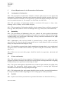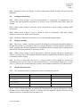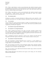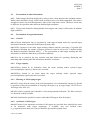
1
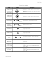
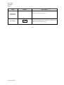
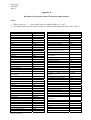
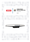
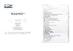
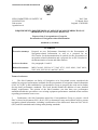
INTERNATIONAL MARITIME ORGANIZATION
E
IMO
SUB-COMMITTEE ON SAFETY OF
NAVIGATION
50th session
Agenda item 4
NAV 50/4
23 March 2004
Original: ENGLISH
REQUIREMENTS FOR THE DISPLAY AND USE OF AIS INFORMATION ON
SHIPBORNE NAVIGATIONAL DISPLAYS
Report of the Correspondence Group for
Presentation of Navigation-related Information
Submitted by Germany
SUMMARY
Executive summary:
Proposal on new Performance Standards for the Presentation of
Navigation-related Information as well as a proposal for an
SN Circular for the harmonization of symbols for the presentation of
navigation-related information and a proposal for an SN Circular for
the harmonization of terms and abbreviations.
Action to be taken:
See paragraphs 11 and 12
Related documents:
MSC/Circ.982, SN/Circ.217, NAV 47/13, NAV 48/4/1, NAV 48/19,
NAV 49/4, NAV 49/4/1 and NAV 49/19
Terms of reference
1
The Sub-Committee on Safety of Navigation at its forty-ninth session considered the
outline for proposed performance standards for the presentation of navigation-related information
(NAV 49 /4 (IEC)) and established a Correspondence Group to progress the work and to further
develop draft performance standards. This work should include the addition of more detailed
display requirements. The opinion of the Sub-Committee was that these new performance
standards should take precedence over existing equipment performance standards when conflicts
regarding presentation issues occur.
2
Furthermore, the Sub-Committee tasked the Correspondence Group to prepare a draft
SN/Circ based on document NAV 49/4/1 (IEC) to harmonize terms and symbols used to present
navigation-related information, including consideration of the differences between NAV 49/4/1
(IEC) and ISO standards and existing radar/plotting standards.
For reasons of economy, this document is printed in a limited number. Delegates are
kindly asked to bring their copies to meetings and not to request additional copies.
I:\NAV\50\4.DOC
NAV 50/4
-2-
The work of the Correspondence Group
3
Members of the Correspondence Group included France, Germany, Japan, Norway,
Poland, Sweden, United Kingdom, the United States, and the following non-governmental
organizations: International Electrotechnical Commission (IEC), International Hydrographic
Organization (IHO) and the International Organization for Standardization (ISO).
4
The Correspondence Group began with the structure of the outline for proposed
performance standards ((NAV 49/4 (IEC)) and developed detailed requirements for the
presentation of navigation-related information. The requirements are based on presentation
requirements from existing performance standards (e.g. radar and ECDIS). For the sake of
completeness some requirements were transferred from individual performance standards. This
fact should be regarded in case of revision of individual performance standards.
Detailed requirements for the presentation of AIS information were developed on the basis of
SN/Circ.217. This work was conducted in close co-operation with the Correspondence Group on
Radar. As a result the requirements for the presentation of AIS information are listed in the draft
performance standards on Presentation of Navigation-related Information and the operational and
functional requirements for the display of AIS target information are listed in the draft revised
performance standards for Shipborne Radar equipment.
Draft performance standards for the Presentation of Navigation-related Information are attached
as annex 1.
5
The Correspondence Group started with document NAV 49/4/1 (IEC) and developed a
proposal for harmonized symbols. The task was to harmonize navigational symbols, especially
the symbols for own ship, radar targets and AIS targets. During development, the
Correspondence Group considered the following:
•
Symbols should be based on symbology currently in use
•
Only minimum changes to existing symbols should be applied
•
New or modified symbols should be introduced only when needed
•
Symbols should be arranged into logical functional groups with a common base symbol
•
Symbol should be consistent between logical functional groups
•
The total number of symbols should be kept to a minimum
•
Symbols should be distinguishable by shape or outline rather than colour alone
•
Symbols should be designed using as few colours as possible
Conflicts were identified in the presentation of several existing symbols. As a result, a consistent
solution was determined for the presentation of the own ship symbol, radar symbols and AIS
symbols. These three classes of symbols are discriminated by shape, e.g. radar symbols based on
a circle, and AIS symbols based on an oriented triangle. For radar and AIS targets the functional
state, e.g. danger state, is coded consistently by applying additional attributes to the base symbol.
A draft SN Circular for the harmonization of symbols for the presentation of navigation-related
information is attached as annex 2.
I:\NAV\50\4.DOC
-3-
NAV 50/4
6
For safety reasons the terms and abbreviations used for the display of navigation-related
information on all shipborne navigation equipment and systems should be consistent. Based on
NAV 49/4/1 (IEC) and ISO standards, the Correspondence Group prepared a harmonized list of
terms and abbreviations for use in the presentation of navigation-related information. The list was
developed together with IEC and ISO experts and represents a concerted solution.
A draft SN Circular for terms and abbreviations is attached as annex 3.
Additional findings
7
Based on more practical experience gained with the onboard use of AIS, the Interim
Guidelines for the Presentation and Display of AIS Target Information (SN/Circ.217) should be
replaced by:
•
The presentation requirements from the draft Performance Standards for the Presentation
of Navigation-related Information (attached as annex 1)
•
The functional requirements from the draft revision of the Performance Standards for
Shipborne Radar equipment (NAV 50/9)
•
The symbology listed in the draft Guidelines for the Presentation of Navigation-related
Symbols (attached as annex 2).
8
During the development of the draft Performance Standards for the Presentation of
Navigation-related Information, the Correspondence Group noticed that definitions for common
terms are often different in the various Performance Standards. For that reason the
Correspondence Group recommends the development of guidelines for navigation-related
definitions, which should replace the definitions in the individual Performance Standards.
9
During the development of the draft performance standards for the Presentation of
Navigation-related Information, the Correspondence Group identified the lack of a common
approach or organizational structure for navigation-related alarms and indications. For that
reason the Correspondence Group recommends the development of guidelines for the
management and presentation of navigation-related alarms and indications, which should include
prioritisation for presentation.
10
It was further noticed that the existing performance standards for ECDIS contain some
inconsistencies and are lacking in the area of the operational requirements for chart data
processing. The Correspondence Group therefore recommends a review of the performance
standards for ECDIS as well as the referring standards in order to clarify operational
requirements and introduce new requirements for ECDIS. This may result in a recommendation
to revise the existing performance standards for ECDIS.
Actions requested of the Sub-Committee
11
The Sub-Committee is invited to consider and approve the following;
.1
the draft performance standards attached as annex 1, recognizing their close
relationship with the proposed revised performance standards for shipborne radar
equipment;
.2
the draft SN Circular on guidelines for the presentation of navigation-related
symbols attached as annex 2;
I:\NAV\50\4.DOC
NAV 50/4
.3
-4-
the draft SN Circular on guidelines for the presentation of navigation-related
terms and abbreviations attached as annex 3;
12
The Sub-Committee is also invited to further consider the following and decide as
appropriate;
.1
the additional findings in paragraph 7 with respect to SN/Circ.217;
.2
the additional findings in paragraph 8 with respect to the need for harmonized
definitions;
.3
the additional findings in paragraph 9 with respect to alarms and indications; and
.4
the additional findings in paragraph 10 with respect to the performance standards
for ECDIS, recognizing their close relationship with the draft performance
standards for the presentation of navigation-related information.
***
I:\NAV\50\4.DOC
NAV 50/4
ANNEX 1
DRAFT PERFORMANCE STANDARDS FOR THE
PRESENTATION OF NAVIGATION-RELATED INFORMATION
1
Purpose
These performance standards harmonise the requirements for the presentation of
navigation-related information on the bridge of a ship to ensure that all navigational displays
adopt a consistent human machine interface philosophy and implementation.
These performance standards supplement and in case of a conflict, take priority over,
presentation requirements of the individual performance standards adopted by the Organization
for relevant navigational systems and equipment, and cover the presentation of navigation-related
information by equipment for which performance standards have not been adopted.
2
Scope
These performance standards specify the presentation of navigational information on the bridge
of a ship, including the consistent use of navigational terms, abbreviations, colours and symbols,
as well as other presentation characteristics.
These performance standards also address the presentation of navigation information related to
specific navigational tasks by recognizing the use of user selected presentations in addition to
presentations required by the individual performance standards adopted by the Organization.
3
Application
The general principles of these standards are applicable for all displays on the bridge of a ship.∗
These performance standards are applicable to any display equipment associated with the
navigation systems and equipment for which individual performance standards have been
adopted by the Organization. They also address display equipment associated with navigation
systems and equipment for which individual performance standards have not been adopted.
In addition to the general requirements set out in resolution A.694(17)**, and the guidelines set
out in MSC/Circ.982, display equipment should meet the requirements of these performance
standards, as applicable.
4
Definitions
For definitions see Appendix 1.
∗ The general principles are addressed in paragraphs 5 and 8.
** IEC Publication 60945 (see Appendix 1).
I:\NAV\50\4.DOC
NAV 50/4
ANNEX 2
Page 2
5
General Requirements for the Presentation of Information
5.1
Arrangement of information
5.1.1 The presentation of information should be consistent with respect to screen layout and
arrangement of information. Data and control functions should be logically grouped. Priority of
information should be identified for each application, permanently displayed and presented to the
user in a prominent manner by, for example, use of position, size and colour.
5.1.2 The presentation of information should be consistent with respect to values, units,
meaning, sources, validity, and if available, integrity.
5.1.3 The presentation of information should be clearly separated into an effective operational
area (e.g. radar, chart) and one or more user dialogue areas (e.g. menus, data, control functions).
5.2
Readability
5.2.1 The presentation of alphanumeric data, text, symbols and other graphical information
(e.g. radar image) should support readability from typical user positions under all ambient light
conditions likely to be experienced on the bridge of a ship, with due consideration to the night
vision of the officer of the watch.
5.2.2 Alphanumeric data and text should be presented using a clearly legible non-italic,
sans-serif font. The font size should be appropriate for the viewing distance from user positions
likely to be experienced on the bridge of a ship.
5.2.3 Text should be presented using simple unambiguous language that is easy to understand.
Navigation terms and abbreviations should be presented using the nomenclature defined in
SN/Circ.[..].
5.2.4 When icons are used, their purpose should be intuitive by appearance, placement and
grouping.
5.3
Colours and intensity
5.3.1 The colours used for the presentation of alphanumeric data, text, symbols and other
graphical information should provide sufficient contrast against the background under all lighting
conditions likely to be experienced on the bridge of a ship.
5.3.2 The colours and brightness should take into account the light conditions of daylight, dusk
and night. The presentation should support night viewing by showing light foreground
information on a dark non-reflecting background at night.
5.3.3 The background colour and contrast should be chosen to allow presented information to
be easily discriminated without degrading the colour coding aspects of the presentation.
5.4
Symbols
5.4.1
Symbols used for the presentation of operational information are defined in SN/Circ.[..].
I:\NAV\50\4.DOC
NAV 50/4
ANNEX 2
Page 3
5.4.2 Symbols used for the display of charted information should comply with relevant IHO
standards.
5.5
Coding of information
5.5.1 When colour coding is used for discrimination or conspicuity of alphanumeric text,
symbols and other graphical information, all colours in the set should clearly differ from one
another.
5.5.2 When colour coding is used, the colour red should be used for coding of alarm related
information.
5.5.3 When colour coding is used, it should be used in combination with other symbol
attributes, such as size, shape, and orientation.
5.5.4
Flashing of information should be reserved for unacknowledged alarms.
5.6
Integrity marking
5.6.1 The source, validity, and where possible, the integrity of information should be indicated.
Invalid information or information with low integrity should be clearly marked, qualitatively
and/or quantitatively. Invalid information or information with low integrity may be quantitatively
indicated by displaying absolute or percentage values.
5.6.2 When colour coding is used, information with low integrity should be qualitatively
marked by using yellow, and invalid information should be qualitatively marked by using red or
by deletion from the display.
5.6.3 In order to show that the screen is being refreshed, means should be provided to
immediately make the user aware of a presentation failure on an operational display (e.g. “picture
freeze”). [This may be accomplished by a positive and continuous indication or by other means.]
5.7
Alarms and indications
5.7.1
The operational status of information should be indicated as follows:
Status
Visual Indication
Audible Signal
Alarm, not acknowledged
Red, flashing
Accompanied by an audible signal
Alarm, acknowledged
Invalid Information
Red
Suppression of audible signal
Important Indications [Warnings]
(e.g. low integrity)
Yellow
Silence
Normal state
None required, optionally green
Silence
5.7.2 A list of alarms should be provided with consideration for priority and sequence. Alarms
that have been acknowledged and are no longer relevant should be deleted from the list of
alarms, but may be retained in an alarm history list.
I:\NAV\50\4.DOC
NAV 50/4
ANNEX 2
Page 4
5.7.3 When a single display is used to present information from multiple navigation systems
and equipment, the presentation of alarms and indications should be consistent for the display of
the time of alarm occurrence, the cause of the alarm, the source of the alarm and the status of the
alarm (e.g. unacknowledged, acknowledged).
5.7.4 When a single display is used to present information from multiple navigation systems
and equipment, a simple operator action should acknowledge the alarms from multiple
navigation systems caused by the same initial event.
5.8
Presentation modes
If displays are capable of presenting information in different mode(s), there should be a clear
indication of the mode in use, for example orientation, stabilization, motion, and chart projection.
5.9
User manuals
The user manual and operator instructions should be available in the English language. The user
manual or reference guide should include a list of all terms, abbreviations, and symbols and their
explanations presented by the equipment.
6
Presentation of Operational Information
6.1
Presentation of own ship information
6.1.1 When a graphical representation of own ship is provided, it should be possible for the
user to select either a scaled ship’s outline or a simplified symbol as specified in SN/Circ [..]. The
size of the ship’s outline or the simplified symbol in the graphical presentation should be the true
scale size of the ship or 6mm, whichever is greater.
6.1.2 A heading line, and where appropriate a velocity vector, should be associated with own
ship symbol and should originate at the position of the consistent common reference point.
6.2
Presentation of charted information
6.2.1 The presentation of charted information that is issued by, or on the authority of a
government authorised hydrographic office, or other relevant government institution should
comply with the relevant IHO standards.
6.2.2 The presentation of proprietary charted information should comply with IHO standards,
(e.g. IHO S-52 and IHO S-61), as far as practical. There should be a clear indication when the
presentation is not in accordance with IHO standards.
6.2.3 The presentation of user-added charted information should comply with the relevant IHO
standards, as far as practical.
6.2.4 If chart data derived from different scales appear on the display, the scale boundary
should be clearly indicated.
I:\NAV\50\4.DOC
NAV 50/4
ANNEX 2
Page 5
6.3
Presentation of radar information
6.3.1 Radar images should be displayed by using a basic colour that provides optimum contrast.
Radar echoes should be clearly visible when presented on top of a chart background. The relative
strength of echoes may be differentiated by tones of the same basic colour. The basic colour may
be different for operation under different ambient light conditions.
6.3.2 Target trails should be distinguishable from targets and clearly visible under all ambient
light conditions.
6.4
Presentation of target information
6.4.1
General
6.4.1.1 Target information may be provided by radar target tracking and/or by reported target
information from the Automatic Identification System (AIS).
6.4.1.2 The operation of the radar target tracking function and the processing of reported AIS
information, including the number of targets presented, related to screen size, is defined within
the Radar Performance Standard, MSC […]. The presentation of radar target tracking and AIS
information is defined within these performance standards.
6.4.1.3 As far as practical, the user interface and data format for operating, displaying and
indicating radar tracking and AIS information should be consistent.
6.4.2
Target capacity
6.4.2.1 There should be an indication when the target tracking and/or reported target
processing/display capacity is about to be exceeded.
6.4.2.2 There should be an alarm when the target tracking and/or reported target
processing/display capacity has been exceeded.
6.4.3
Filtering of AIS sleeping targets
6.4.3.1 To ensure that the clarity of the total presentation is not substantially impaired, it should
be possible to filter the presentation of sleeping AIS targets (e.g. by target range, CPA/TCPA or
AIS target class A/B, etc.).
6.4.3.2 If a filter is applied, there should be a clear and permanent indication. The filter criteria in
use should be readily available.
6.4.3.3 It should not be possible to remove individual AIS targets from the display.
6.4.4
Activation of AIS targets
6.4.4.1 If zones for the automatic activation of AIS targets are provided, they should be the same
as for automatic radar target acquisition, if available. Any user defined zones
(e.g. acquisition/activation zones) in use should be presented in graphic form.
I:\NAV\50\4.DOC
NAV 50/4
ANNEX 2
Page 6
6.4.4.2 In addition, sleeping AIS targets should be automatically activated when meeting user
defined parameters (e.g. target range, CPA/TCPA or AIS target class A/B).
6.4.5
Graphical presentation
6.4.5.1 Targets should be presented with their relevant symbols according to SN/Circ.[..].
6.4.5.2 AIS information should be graphically presented either as sleeping or activated targets.
6.4.5.3 The course and speed of a tracked radar target or reported AIS target should be indicated
by a vector that clearly shows the predicted motion. The vector time (length) should be consistent
for presentation of any target regardless of its source.
6.4.5.4 The presentation of vector symbols should be consistent irrespective of the source of
information. The presentation mode should be clearly and permanently indicated, including for
example: True/Relative vector, vector time and vector stabilisation.
6.4.5.5 The orientation of the AIS target symbol should indicate its heading. If the heading
information is not received, the orientation of the AIS symbol should be aligned to the COG.
When available, the turn or rate of turn (ROT) indicator and/or the path prediction should
indicate the manoeuvre of an activated AIS target.
6.4.5.6 A consistent common reference point should be used for the alignment of tracked target
symbols and AIS target symbols with other information on the same display.
6.4.5.7 On large scale / low range displays, a means to present a true scale outline of an activated
AIS target should be provided.
6.4.5.8 It should be possible to display the past positions of activated targets.
6.4.6 Target data
6.4.6.1 A target selected for the display of its alphanumeric information should be identified by
the relevant symbol. If more than one target is selected for data display, the symbols and the
corresponding data should be clearly identified.
6.4.6.2 There should be a clear indication to show that the target data is derived from radar or
AIS or from a combination of these.
6.4.6.3 For each selected tracked radar target the following data should be presented in
alphanumeric form: Source(s) of data, measured range of target, measured bearing of target,
predicted target range at the closest point of approach (CPA), predicted time to CPA (TCPA),
true course of target, true speed of target. Additional target information should be provided on
request.
6.4.6.4 For each selected AIS target the following data should be presented in alphanumeric
form: Source of data, ship’s identification, position and its quality, calculated range of target,
calculated bearing of target, CPA, TCPA, COG, SOG, navigational status. Ship’s heading and
rate of turn should also be made available. Additional target information should be provided on
request.
I:\NAV\50\4.DOC
NAV 50/4
ANNEX 2
Page 7
6.4.6.5 If the received AIS information is incomplete, the absent information should be clearly
indicated in the target data field as missing.
6.4.6.6 The data should be displayed and continually updated, until another target is selected for
data display or until the window is closed.
6.4.6.7 Means should be provided to present own ship AIS data on request.
6.4.6.8 The alphanumeric displayed data should not obscure graphically presented operational
information.
6.4.7
Operational alarms
6.4.7.1 A clear indication of the status of the alarms and of the alarm criteria should be given.
6.4.7.2 A CPA/TCPA alarm of a tracked radar or activated AIS target should be clearly indicated
and the target should be clearly marked by a dangerous target symbol.
6.4.7.3 If a user defined acquisition/activation zone facility is provided, a target entering the zone
should be clearly identified with the relevant symbol and for tracked radar targets an alarm
should be given. The zone should be identified with the relevant symbology, and should be
applicable to tracked radar and AIS targets.
6.4.7.4 The last position of a lost target should be clearly marked by a lost target symbol on the
display, and the lost target alarm should be given. The lost target symbol should disappear if the
signal is received again, or after the alarm has been acknowledged. There should be a clear
indication whether the lost target alarm function for AIS targets is enabled or disabled.
6.4.8
AIS and radar target association
6.4.8.1 An automatic target association function serves to avoid the presentation of two target
symbols for the same physical target. If target data from AIS and radar tracking are both
available and if the AIS and radar information are considered as one target, then as a default
condition, the activated AIS target symbol and the alphanumeric AIS target data should be
automatically selected and displayed. The user should have the option to change the default
condition to the display of tracked radar targets and should be permitted to select either radar
tracking or AIS alphanumeric data.
6.4.8.2 If the AIS and radar information are considered as two distinct targets, one activated AIS
target and one tracked radar target should be displayed. No alarm should be raised.
I:\NAV\50\4.DOC
NAV 50/4
ANNEX 2
Page 8
6.4.9 AIS presentation status
The AIS presentation status should be indicated as follows:
Function
Cases to be Presented
Presentation
AIS ON / OFF
AIS processing switched on AIS processing switched ON
/ graphical presentation
/ graphical presentation
switched OFF
switched ON
Alphanumeric or graphical
Filtering of
sleeping AIS
targets
(6.4.3)
Filter status
Filter status
Alphanumeric or graphical
Activation criteria
Graphical
Function ON/OFF
Function ON/OFF
Alphanumeric
CPA/TCPA Criteria
CPA/TCPA Criteria
Activation of
Targets
(6.4.4)
CPA/TCPA
Alarm
(6.4.7)
Sleeping targets included
Sleeping targets included
Lost Target
Alarm
(6.4.7)
Function ON/OFF
Function ON/OFF
Lost target Filter Criteria
Lost target Filter Criteria
Target
Association
(6.4.8)
Function ON/OFF
Function ON/OFF
Association Criteria
Association Criteria
Default Target Priority
Default Target Priority
Alphanumeric
Alphanumeric
6.4.10 Trial manoeuvre
A trial manoeuvre simulation should be clearly identified by the relevant symbol positioned
astern of own ship within the effective operational area of the screen.
7
Operational Displays
7.1
General
7.1.1 If the display equipment is capable of supporting the presentation of multiple functions
then there should be a clear indication of the primary function supported by the presentation
(e.g. Radar, ECDIS). It should be possible to select the Radar presentation (see 7.1.) or the
ECDIS presentation (see 7.2.) by a single operator action.
7.1.2 If a radar image and an electronic chart are displayed together, the chart and the radar
image should use a consistent common reference point and match in scale, projection and
orientation. Any offset should be indicated.
7.1.3 Range scales of 0.25, 0.5, 0.75, 1.5, 3, 6, 12 and 24 NM should be provided. Additional
range scales are permitted. These range scales do not apply when presenting raster chart data.
The range scale should be permanently indicated.
7.1.4
When range rings are displayed, the range separation should be indicated.
I:\NAV\50\4.DOC
NAV 50/4
ANNEX 2
Page 9
7.1.5 No part of the effective operational area should be permanently used for presentation of
information that is not part of the navigation presentation (e.g. pop up displays, drop down menus
and information windows). Temporary, limited and relevant alphanumeric data may be displayed
adjacent to a selected symbol, graphic or target within the effective operational area.
7.2
Radar display
7.2.1 Radar video, tracked radar targets and AIS targets should not be substantially degraded,
masked or obscured by other presented information.
7.2.2 It should be possible to temporarily suppress all graphical information from the display,
retaining only radar video and trails.
7.2.3 The brightness of radar echoes and associated graphic symbols for tracked radar targets
should be variable. It should be possible to control the brightness of all displayed information.
There should be independent means to adjust the brightness of groups of displayed graphics and
alphanumeric data. The brilliance of the heading line should not be variable to extinction.
7.2.4
Display of chart information on radar
7.2.4.1 Vector chart information may be displayed on a radar presentation. This should be
accomplished using layers selected from the chart database. As a minimum, the elements of the
Display Base should be available for individual selection by category or layer, but not as
individual objects. As far as practical, chart information should be presented in accordance with
the ECDIS performance standard and with these presentation standards.
7.2.4.2 If chart information is displayed within the effective display area, the display of radar
information should have priority. The chart information should be clearly perceptible as such.
The chart information should not substantially degrade, mask or obscure the radar video, tracked
radar targets and AIS targets.
7.2.4.3 There should be an indication of the status of chart information, including source and
update information.
7.2.5
Display of maps on radar
Map graphics may be displayed, but should not substantially degrade, mask or obscure the radar
video, tracked radar targets and AIS targets.
7.3
ECDIS display
7.3.1 The ENC and all updates to it should be displayed without any degradation of their
information content.
7.3.2 Chart information should not be substantially degraded, masked or obscured by other
presented information.
7.3.3 It should be possible to temporarily suppress all supplemental information from the
display, retaining only chart related information contained in the Display Base.
I:\NAV\50\4.DOC
NAV 50/4
ANNEX 2
Page 10
7.3.4 It should be possible to add or remove information from the ECDIS display. It should not
be possible to remove information contained in the Display Base from the ECDIS display.
7.3.5 It should be possible to select a safety contour from the depth contours provided by the
ENC. The safety contour should be emphasized over other contours on the display.
7.3.6 It should be possible to select a safety depth. Soundings equal to or less than the safety
depth should be emphasized whenever spot soundings are selected for display.
7.3.7 An indication should be provided if the information is displayed at a larger scale than that
contained in the ENC, or if own ship's position is covered by an ENC at a larger scale than that
provided by the display.
7.3.8
Overscaled areas shown on the ECDIS display should be identified.
7.3.9 Display of radar information on ECDIS
7.3.9.1 Radar and target information may be displayed on ECDIS but should not substantially
degrade, mask or obscure the chart information. As far as practical, radar and target information
should be presented in accordance with the radar performance standard and with these
presentation standards.
7.3.9.2 Radar and target information should be clearly distinguishable from the chart information.
It should be possible to remove this information by a single operator action.
7.3.10 Display of additional information on ECDIS
7.3.10.1 Information from additional sources may be displayed on ECDIS but should not
substantially degrade, mask or obscure the chart information.
7.3.10.2 Additional information should be clearly distinguishable from the chart information. It
should be possible to remove this information by a single operator action.
7.4
User selected (task orientated) presentation
7.4.1 The user may configure a presentation for a specific task at hand. The presentation may
include radar and/or chart information, in combination with other navigation or ship related data.
When not fully compliant with the Radar or ECDIS performance standards, such a presentation
should be identified as an auxiliary presentation.
7.4.2 As far as practical, the presentation of any radar and/or ECDIS related functions should
be compliant with the requirements of the relevant performance standards and of these
presentation standards, with the exception of size requirements for the operational area. Chartlets
or windows of radar information may be presented along with other information associated with
the task at hand.
I:\NAV\50\4.DOC
NAV 50/4
ANNEX 2
Page 11
8
Physical Requirements
8.1
Display adjustment
8.1.1 It should be possible to adjust the contrast and brightness of the display provided, as
applicable to the display technology. It should be possible to dim the display. The range of the
dimming control should permit the display to be legible under all ambient light conditions.
8.1.2 It should be possible for the navigator to reset the values of contrast and /or brightness to
a preset or default condition.
8.1.3 Where magnetic fields degrade the presentation of navigation information, a means to
neutralise the effect of magnetic fields should be provided.
8.2
Screen size
8.2.1 Display equipment should be of sufficient size to support the requirements of the relevant
performance standards adopted by the Organization.
8.2.2 The effective screen surface of the chart presentation for route monitoring should be at
least 270 x 270 mm.
8.2.3 The effective screen surface of the radar presentation should be at least:
- 195 x 195 mm for vessels smaller than 500 GT;
- 270 x 270 mm for vessels larger than 500 GT and HSC less than 10000 GT;
- 340 x 340 mm for vessels larger than 10000 GT.
8.3
Colours
8.3.1 Multicoloured display equipment should be used except where monochrome displays are
permitted within individual performance standards adopted by the Organization.
8.3.2 Multicoloured operational displays including multifunction displays (e.g. conning
displays) should provide a minimum of 64 colours except where permitted or not required by the
Organization, or when used for a single specific purpose (e.g. speed log, echo-sounder).
8.4
Screen resolution
Operational display equipment including multifunction displays (e.g. conning displays) should
provide a minimum screen resolution of 1280 x 1024, or equivalent for a different aspect ratio,
except where permitted or not required by the Organization, or when used for a single specific
purpose (e.g. speed log, echo-sounder).
8.5
Screen viewing angle
The display should support the reading of information under all ambient light conditions,
simultaneously, by at least two users, from standing and sitting operator positions likely to be
found on the bridge of a ship.
I:\NAV\50\4.DOC
NAV 50/4
ANNEX 2
Page 12
Appendix 1 – Definitions
Activated AIS target
A target representing the automatic or manual activation of
a sleeping target for the display of additional graphically
presented information.
AIS target
A target generated from an AIS message.
Associated target
A target simultaneously representing a tracked radar target
and AIS target having similar parameters (e.g. position,
course, speed) and which comply with an association
algorithm
CCRP
The Consistent Common Reference Point is a location on
own ship, to which all horizontal measurements such as
target range, bearing, relative course, relative speed,
closest point of approach (CPA) or time to closest point of
approach (TCPA) are referenced, typically the conning
position of the bridge.
Dangerous target
A target with a predicted CPA and TCPA that violates
values preset by the operator. The respective target is
marked by a “dangerous target” symbol.
Display Base
The level of SENC information which cannot be removed
from the ECDIS display, consisting of information which
is required at all times in all geographic areas and all
circumstances. It is not intended to be sufficient for safe
navigation.
Effective Operational Display Area Area of the display presenting the situation display,
excluding the user dialog area.
Heading
Direction in which the bow of a ship is pointing expressed
as an angular displacement from north.
Important Indication
A marking of an operational status of displayed
information which needs special attention, e.g. information
with low integrity or invalid information.
Lost target
A target representing the last valid position of a target
before its data was lost. The target is displayed by a “lost
target” symbol.
Past positions
Equally time-spaced past position marks of a tracked or
reported target and own ship. The co-ordinates used to
display past positions may be either relative or true.
I:\NAV\50\4.DOC
NAV 50/4
ANNEX 2
Page 13
Sleeping AIS target
A target indicating the presence and orientation of a vessel
equipped with AIS in a certain location. The target is
displayed by a “sleeping target” symbol. No additional
information is presented until activated.
Selected target
A target selected manually for the display of detailed
alphanumeric information in a separate data display area.
The target is displayed by a “selected target” symbol.
SENC
System electronic navigational chart (SENC) means a
database resulting from the transformation of the ENC by
ECDIS for appropriate use, updates to the ENC by
appropriate means, and other data added by the mariner. It
is this database that is actually accessed by ECDIS for the
display generation and other navigational functions, and is
the equivalent to an up-to-date paper chart. The SENC
may also contain information from other sources.
Trial manoeuvre
Facility used to assist the operator to perform a proposed
manoeuvre for navigation and collision avoidance
purposes, by displaying the predicted future status of all
tracked and AIS targets as a result of own ship’s simulated
manoeuvres.
User Dialog Area
An area of the display consisting of data fields and/or
menus that is allocated to the interactive presentation and
entry or selection of operational parameters, data and
commands mainly in alphanumeric form.
User Selected Presentation
An auxiliary presentation configured by the user for a
specific task at hand. The presentation may include radar
and/or chart information, in combination with other
navigation or ship related data.
***
I:\NAV\50\4.DOC
NAV 50/4
ANNEX 2
Draft SN Circular onGuidelines for the Presentation of Navigation-related Symbols
1
Purpose
The purpose of these annexed guidelines is to provide guidance on the appropriate use of
navigation-related symbols to achieve a harmonized and consistent presentation.
2
Scope
The use of these guidelines will insure that the symbols used for the display of navigation-related
information on all shipborne navigational systems and equipment are presented in a consistent
and uniform manner.
3
Application
These guidelines apply to all shipborne navigational systems and equipment. The symbols listed
in Appendix A should be used for the display of navigation-related information to promote
consistency in the symbol presentation on navigational equipment.
The symbols listed in Appendix A should replace symbols which are currently contained in
existing performance standards. Where a standard symbol is not available, another symbol may
be used, but this symbol should not conflict with the symbols listed in Appendix A.
These guidelines and updates should be made available to the mariner via appropriate means,
(e.g. Notices to Mariners).
I:\NAV\50\4.DOC
NAV 50/4
ANNEX 3
Page 2
Appendix A
Navigation-related Symbols
Table 1: Own Ship Symbols
Topic
Symbol
Description
Double circle, located at own ship’s reference position.
Own ship
Own Ship True
scale outline
Use of this symbol is optional, if own ship position is
shown by the combination of Heading Line and Beam
Line.
True scale outline located relative to own ship’s
reference position, oriented along own ship’s heading.
Used on small ranges/large scales.
Own Ship Radar
Antenna Position,
Cross, located on a true scale outline of the ship at the
physical location of the radar antenna that is the current
source of displayed radar video.
Own Ship Heading
line
Solid line thinner than the speed vector line style, drawn
to the bearing ring or of fixed length, if the bearing ring
is not displayed. Origin is at own ship’s reference point.
Own Ship Beam
line
Solid line of fixed length; optionally length variable by
operator. Midpoint at own ship’s reference point.
Dashed line – short dashes with spaces approximately
twice the line width of heading line.
Own Ship Speed
vector
Time increments between the origin and endpoint may
optionally be marked along the vector using short
intersecting lines.
To indicate Water/Ground stabilization optionally one
arrowhead for water stabilization and two arrowheads for
ground stabilization may be added.
Own Ship Path
prediction
Own Ship
Past Track
A curved vector may be provided as a path predictor.
Thick line for primary source. Thin line for secondary
source.
Optional time marks are allowed.
I:\NAV\50\4.DOC
NAV 50/4
Table 2: Tracked Target Symbols (ARPA, ATA)
Topic
Symbol
Description
Solid filled or unfilled circle located at target position.
The course and speed vector should be displayed as
dashed line, with short dashes with spaces approximately
twice the line width.
Tracked Target
including
Dangerous Target
Optionally, time increments, may be marked along the
vector.
For a “Dangerous Target”, bold, red solid circle with
course and speed vector, flashing until acknowledged.
Circle segments in the acquired target state.
Target in
Acquisition State
For automatic acquisition, bold circle segments, flashing
and red until acknowledged.
Bold lines across the circle, flashing until acknowledged.
Lost Target
A square indicated by its corners centred around the
target symbol.
Selected Target
Target Past
Positions
Tracked Reference
Target
I:\NAV\50\4.DOC
Dots, equally spaced by time.
R
Large R adjacent to designated tracked target
Multiple reference targets should be marked as R1, R2,
R3, etc.
NAV 50/4
ANNEX 3
Page 4
Table 3: AIS Target Symbols
Topic
AIS Target
(sleeping)
Symbol
Description
An isosceles, acute-angled triangle should be used. The
triangle should be oriented by heading, or COG if
heading missing. The reported position should be
located at centre and half the height of the triangle. The
symbol of the sleeping target should be smaller than that
of the activated target.
An isosceles, acute-angled triangle should be used. The
triangle should be oriented by heading, or COG if
heading missing. The reported position should be
located at centre and half the height of the triangle.
Activated AIS
Target
Including
Dangerous Target
The COG/SOG vector should be displayed as a dashed
line with short dashes with spaces approximately twice
the line width. Optionally, time increments may be
marked along the vector.
The heading should be displayed as a solid line thinner
than speed vector line style, length twice of the length of
the triangle symbol. Origin of the heading line is the
apex of the triangle.
The turn should be indicated by a flag of fixed length
added to the heading line.
A path predictor may be provided as curved vector.
For a “Dangerous AIS Target”, bold, red solid triangle
with course and speed vector, flashing until
acknowledged.
A true scale outline may be added to the triangle
symbol. It should be:
AIS Target – True
Scale Outline
Located relative to reported position and according to
reported position offsets, beam and length. Oriented
along own ship’s heading.
Used on low ranges/large scales.
Selected target
Lost target
A square indicated by its corners should be drawn
around the target symbol.
Triangle with bold solid cross. The triangle should be
oriented per last known value. The cross should have a
fixed orientation. The symbol should flash until
acknowledged.
The target should be displayed without vector, heading
and rate of turn indication.
Target Past
Positions
I:\NAV\50\4.DOC
Dots, equally spaced by time.
NAV 50/4
Table 4: Other Symbols
Topic
Symbol
Description
AIS Based AtoN
Diamond with crosshair centred at reported position.
Real Position of
Charted Object
(Shown with chart symbol. Chart symbol not required
for radar.)
AIS Based AtoN
Diamond with crosshair centred at reported position.
Virtual position
Monitored Route
Dashed bold line, waypoints (WPT) as circles
Planned or
Alternate Route
Dotted line, WPT as circles
Trial Manoeuvre
Large [red] T on screen
Simulation Mode
Cursor
Range Rings
Variable Range
Markers (VRM)
Electronic Bearing
Lines (EBL)
I:\NAV\50\4.DOC
S
Large [red] S on screen
Crosshair (two alternatives, one with open centre).
Solid circles
Circle.
Additional VRM should be distinguishable from the
primary VRM.
Dashed line.
Additional EBL should be distinguishable from the
primary EBL.
NAV 50/4
ANNEX 3
Page 6
Topic
Acquisition /
Activtion Area
Event Mark
Symbol
Description
Solid line boundary for an area.
Rectangle with diagonal line, clarified by added text (e.g.
“MOB” for man overboard cases).
***
I:\NAV\50\4.DOC
NAV 50/4
ANNEX 3
Draft SN Circular on Guidelines for the Presentation of Navigation-related Terms and
Abbreviations
1
Purpose
The purpose of these annexed guidelines is to provide guidance on the use of appropriate
navigation-related terminology and abbreviations. These are based on terms and abbreviations
used in existing navigation references.
2
Scope
These guidelines are issued to ensure that the terms and abbreviations used for the display of
navigation-related information on all shipborne navigation equipment and systems are consistent
and uniform.
3
Application
These guidelines apply to all shipborne navigational systems and equipment including, radar,
ECDIS, AIS, INS and IBS. When navigation-related information is displayed as text, the
standard terms or abbreviations listed in Appendix B should be used, instead of those contained
in existing performance standards.
Where a standard term or abbreviation is not available, another term or abbreviation may be
used. Such a term or abbreviation should not conflict with the standard terms or abbreviations
listed in Appendix B and should provide a clear meaning. Standard marine terminology should
be used for this purpose. When the meaning is not clear from its context, the term should not be
abbreviated.
Unless otherwise specified, standard terms should be shown in lower case while abbreviations
should be presented using upper case.
These guidelines and updates should be made available to the mariner via appropriate means,
(e.g. Notices to Mariners)
I:\NAV\50\4.DOC
NAV 50/4
ANNEX 3
Page 2
Appendix B
Harmonized Navigation-related Terms and Abbreviations
Notes:
1
2
Where shown as “ - -“, some terms require no abbreviations (e.g. “Aft”).
For abbreviations of terms used in charts, see IHO International Chart Series (INT Chart 1).
Name of term
Acknowledge
Acquisition Zone
Acquisition, Acquire
Additional Secondary Factor
Adjust, Adjustment
Aft
Alarm
Along Track Error
Alternating Current
Altitude
Altitude intercept
Amplitude Modulation
Anchor Watch, Anchorage
Antenna
Anti Clutter Rain
Anti Clutter Sea
Approximate Position
April
Astronomical
Audible
Audio Frequency
August
Automatic
Automatic
Dependent
Surveillance
Automatic Frequency Control
Automatic Gain Control
Automatic Identification System
Automatic Radar Plotting Aid
Automatic Tracking Aid
Autopilot
Autopilot System Data
Auxiliary Equipment
Auxiliary System/Function
Available
Azimuth
Azimuth Indicator
Background
Bearing
Bearing Waypoint To Waypoint
Binary Digit
Bow Crossing Range
Bow Crossing Time
Built in Integrity Test
Built in Test Equipment
Calibrate
I:\NAV\50\4.DOC
Abbreviation
ACK
AZ
ACQ
ASF
ADJ
-ALM
ATE
AC
ALT
Ho – Hc
AM
ANCH
ANT
RAIN
SEA
PA
APR
A
AUD
AF
AUG
AUTO
ADS
AFC
AGC
AIS
ARPA
ATA
AP
ASD
AE
AUX
AVAIL
Zn
AZI
BKGND
BRG
BWW
BIT
BCR
BCT
BIIT
BITE
CAL
Name of term
Cancel
Carried (e.g., carried EBL origin)
Central Processing Unit
Centre
Change
Chart Datum
Circular Error Probable
Circular Polarised
Clear
Closest Point of Approach
(Closest Plotted Approach)
Coast Guard Station
Communication, Navigation and
Surveillance
Compact Disc Read Only Memory
Compass
Compass Bearing
Compass Course
Compass Course (Radar)
Compass Heading
Compass Heading (Radar)
Compass North
Computed altitude
Consistent Common Reference
System
Contrast
Coordinated Universal Time
Correction
Course
Course Deviation Indicator
Course Made Good
Course Of Advance
Course Over the Ground
Course Selective Error
Course Through the Water
Course To Steer
Course Up
Craft
Autonomous
Integrity
Monitoring
Cross Track Distance
Cursor
Curved Heading Line
Dangerous Goods
Data
Date
Day/Night
Abbreviation
CNCL
C
CPU
Cent
CHG
CD
CEP
CP
CLR
CPA
CG
CNS
CD-ROM
-CB
CC
C CRS
CH
C HDG
CN
Hc
CCORS
CONTR
UTC
CORR
CRS
CDI
CMG
COA
COG
CSE
CTW
CTS
C Up
CAIM
XTD
CURS
CHL
DG
--DAY/NT
NAV 50/4
ANNEX 3
Page 3
Name of term
Dead Reckoning, Dead Reckoning
Position
Declination
Decrease
Degauss
Degree(s)
Delay
Delete
Departure
Depth
Destination
Deviation
Differential GLONASS
Differential GNSS
Differential GPS
Digital Selective Calling
Direct Current
Display
Display Brilliance
Distance
Distance Interval
Distance Measuring Equipment
Distance Root Mean Square
Distance To Go
Drift
Dropped
Abbreviation
DR
Dec
DECR
-DEG
-DEL
Dep
DPTH
DEST
DEV
DGLONASS
DGNSS
DGPS
DSC
DC
DISP
BRILL
DIST
DIST INT
DME
dRMS
DTG
-D (e.g., dropped
EBL origin)
East
E
Echo Reference
REF
Electromagnetic Compatibility
EMC
Electromagnetic Interference
EMI
Electronic Bearing Line
EBL
Electronic Chart Display and ECDIS
Information System
Electronic Chart System
ECS
Electronic Navigational Chart
ENC
Electronic Plotting Aid
EPA
Electronic Position Fixing System EPFS
Electronic Range and Bearing ERBL
Line
Electrostatic Discharge
ESD
Emergency Position Indicating EPIRB
Radio Beacon
Enhance
ENH
Enter
ENT
Equipment
EQUIP
Equipment Under Test
EUT
Error
ERR
Estimated Position
EP
Estimated Time of Arrival
ETA
Estimated Time of Departure
ETD
European
Geostationary EGNOS
Navigational Overlay System
Event
-Exclusion Zone
EZ
External
EXT
I:\NAV\50\4.DOC
Name of term
February
Fishing Vessel
Fix
Forward
Frequency Modulation
Full
Gain
Geographic
Geometric Dilution Of Precision
Global Maritime Distress and
Safety System
Global
Navigation
Satellite
System
Global
Orbiting
Navigation
Satellite System
Global Positioning System
Great Circle
Greenwich Hour Angle
Greenwich Mean Time
Grid
Ground Stabilisation
Ground Track
Grounding Avoidance System
Group Repetition Interval
Guard Zone
Gyro
Gyro Bearing
Gyro Bearing (Radar)
Gyro Course
Gyro Course
Gyro Error Correction
Gyro Heading
Gyro Heading (Radar)
Gyro North
Harmful Substances
Head Up
Heading
Heading Control System
Heading Line
Heading Line Off
Heading Marker
Heading Measuring Device
Height of Eye
Height of tide
High Frequency
High Speed Craft
High Water
High Water Height
High Water Time
Horizontal Dilution Of Precision
Human Machine Interface
Identification
In
Increase
Index Correction
Indication
Abbreviation
FEB
FISH
-FWD
FM
--GEOG
GDOP
GMDSS
GNSS
GLONASS
GPS
GC
GHA
GMT
-GND STAB
GND TRK
GAS
GRI
GZ
-GyB
Gy BRG
GyC
Gy CRS
GyE
GyH
Gy HDG
GyN
HS
H Up
HDG
HCS
HL
HL OFF
HM
HMD
HE
H
HF
HSC
HW
HWH
HWT
HDOP
HMI
ID
-INCR
IC
IND
NAV 50/4
ANNEX 3
Page 4
Name of term
Information
Infrared
Initialisation
Input
Input/Output
Integrated Bridge System
Integrated
Communication,
Navigation and Surveillance
Integrated Navigation Systems
Integrated Radio Communication
System
Intended Ground Track
Intended Water Track
Interference Rejection
International Atomic Time
International
Convention
for
Safety of Life at Sea
Interswitch
January
July
June
Label
Latitude
Latitude/Longitude
Leeway
Limit
Line Of Position
Linear Error Probability
Liquid Crystal Display
Local Hour Angle
Local Mean Time
Log
Long Pulse
Long Range
Longitude
Loran
Lost Target
Low Frequency
Low Water
Low Water Height
Low Water Time
Magnetic
Magnetic Bearing
Magnetic Course
Magnetic Course (Radar)
Magnetic Heading
Magnetic Heading (Radar)
Magnetic North
Magnetic Variation
Man Overboard
Manoeuvre Time
Manual Operation
Map(s)
March
Maritime Mobile Service Identity
Maritime Pollutant
I:\NAV\50\4.DOC
Abbreviation
INFO
INF RED
INIT
INP
I/O
IBS
ICNS
INS
IRCS
GT
WT
IR
TAI
SOLAS
ISW
JAN
JUL
JUN
LBL
LAT
L/L
LWY
LIM
LOP
LEP
LCD
LHA
LMT
-LP
LR
LON
LOR
LOST TGT
LF
LW
LWH
LWT
MAG
MB
MC
M CRS
MH
M HDG
MN
MAG VAR
MOB
MVR TIME
MAN
-MAR
MMSI
MP
Name of term
Maritime Safety Information
Marker
Master
Maximum
May
Mean High Water
Mean High Water Neaps
Mean High Water Springs
Mean Latitude
Mean Low Water
Mean Low Water Neaps
Mean Low Water Springs
Medium Frequency
Medium Pulse
Menu
Meridian Passage
Minimum
Missing
Mute
Nadir
Navigation
Normal
North
North Up
Not Less Than
Not More Than
Not Under Command
November
Observed altitude
October
Off
Off Centre
Off Track
Abbreviation
MSI
MKR
MSTR
MAX
-MHW
MHWN
MHWS
Lm
MLW
MLWN
MLWS
MF
MP
-MPAS
MIN
--Na
NAV
NORM
N
N Up
NLT
NMT
NUC
NOV
Ho
OCT
-OFF CENT
OFF TRK
Officer On Watch
Offset
On
Out
Output
Own Ship
Own Ship Data
Panel Illumination
Parallax in horizon
Parallel Index Line
Passenger Vessel
Past Position
Performance Check
Performance Monitor
Performance Test
Permanent
Personal Computer
Personal Identification Number
Pilot Vessel
Plan Position Indicator
Port, Portside
Position
Position Approximate
OOW
---OUT
OS
OSD
PANEL
HP
PI
PASSV
P POSN
PFC
MON
PT
PERM
PC
PIN
PILOT
PPI
-POSN
PA
NAV 50/4
ANNEX 3
Page 5
Name of term
Positional Dilution Of Precision
Power
Power Drive Vessel (Underway
Using Engine)
Predicted Area of Danger
Predicted Point of Collision
Pulse Length
Pulse Modulation
Pulse Repetition Frequency
Pulse Repetition Rate
Pulses Per Revolution
Racon
Radar
Radar Plotting
Radar System Data
Radio Frequency
Radius
Rain
Range
Range Rings
Raster Chart Display System
Raster Navigational Chart
Rate Of Turn
Real-time Kinemetic
Recall
Receiver
Receiver Autonomous Integrity
Monitoring
Reference
Relative
Relative Bearing
Relative Course
Relative Motion
Relative Vector
Restricted in Ability to Manoeuvre
(Restricted Manoeuvrability)
Rhumb Line
Right Ascension
Roll On/Roll Off
Root Mean Square
Route
Safety Contour
Sailing Vessel
Satellite
S-Band
Abbreviation
PDOP
PWR
UWE
PAD
PPC
PL
PM
PRF
PRR
PPR
-RDR
RP
RSD
RF
RAD
-RNG
RR
RCDS
RNC
ROT
RTK
RCL
Rx
RAIM
REF
REL or R
R BRG
R CRS
RM
R VECT
RIM
RL
RA
RoRo
RMS, r.m.s.
RTE
SF CNT
SAIL
SAT
S (only applies
to Radar)
Scan to Scan
SC/SC
Search And Rescue Transponder
SART
Search And Rescue Vessel
SARV
Select
SEL
Semi-diameter
SD
September
SEP
Sequence
SEQ
Set (i.e., set and drift, or setting a -value)
Ship’s Time
-Short Pulse
SP
I:\NAV\50\4.DOC
Name of term
Sidereal Hour Angle
Signal Station
Signal to Noise Ratio
Simulation
Slave
South
Speed
Speed and Distance Measuring
Equipment
Speed Made Good
Speed Of Advance
Speed Over the Ground
Speed Through the Water
Stabilized
Standard Time
Standby
Starboard, Starboard site
Station
Symbols Off
Synchronisation Pulse
System Electronic Navigational
Chart
System Raster Navigational Chart
Target
Target Tracking
Test Target
Time
Time Difference
Time Dilution Of Precision
Time Of Arrival
Time Of Departure
Time to Closest Point of Approach
Time To Go
Time to Wheel Over Line
Total Compass Error Correction
Track
Track Control System
Track Made Good
Tracking
Trail(s)
Transceiver
Transferred Position
Transmitter
Transmitting Compass Heading
Device
Transmitting Heading Device
Transponder
Trial Manoeuvre
Trigger Pulse
True
True altitude
True Bearing (Radar)
True Course (Radar)
True Heading (Radar)
True Motion
True North
Abbreviation
SHA
SS
SNR
SIM
-S
SPD
SDME
SMG
SOA
SOG
STW
STAB
ST
STBY
Stb
STN
SYM OFF
SYNC
SENC
SRNC
TGT
TT
TEST TGT
-TD
TDOP
TOA
TOD
TCPA
TTG
TWOL
CE
TRK
TCS
TMG
TRKG
-TxRx
TPL
Tx
TCHD
THD
TPR
TRIAL
TRIG
T
H
T BRG
T CRS
T HDG
TM
TN
NAV 50/4
ANNEX 3
Page 6
Name of term
True Track
True Vector
Tune
Ultrahigh Frequency
Uninterruptible Power Supply
Universal Time
Universal Transverse Mercator
Unstabilised
Variable Range Marker
Vector
Vector Time
Very High Frequency
Very Low Frequency
Vessel Aground
Vessel at Anchor
Vessel Constrained by Draught
Vessel Engaged in Diving
Operations
Vessel Engaged in Dredging or
Underwater Operations
Vessel Engaged in Towing
Operations
Vessel Traffic Service
Units of Measurement
cable length
candela
cycles per second
fathom(s)
foot
hectopascal
Hertz
hour(s)
inch(es)
Kelvin
kilo Hertz
cbl
cd
cps
fm
ft
hPa
Hz
h
in
K
kHz
Abbreviation
T TRK
T VECT
-UHF
UPS
UT
UTM
UNSTAB
VRM
VECT
VECT TIME
VHF
VLF
GRND
ANCH
VCD
DIVE
DRG
TOW
VTS
Name of term
Video
Video Display Unit
Visual
Voyage
Voyage Data Recorder
Warning
Water Track
Waypoint
Waypoint Bearing
Waypoint Closure Velocity
Waypoint Distance
West
Wheel Over Line
Wheel Over Point
Wheel Over Time
Wide-Area Augmentation System
Word Error Rate
World Geodetic System
X-Band
Zenith
Zone Time
Units of Measurement
kilometre
knot(s)
Mega Hertz
metre(s)
minute(s)
Nautical Mile(s)
nautical miles in charts
pulses per revolution
revolutions per minute
second(s)
Twenty-foot Equivalent Unit
__________
I:\NAV\50\4.DOC
km
kn
MHz
m
min
NM
M
PPR
rpm
s
TEU
Abbreviation
VID
VDU
V
VOY
VDR
WNG
WAT TRK
WPT
WPB
WCV
WPD
W
WOL
WOP
WOT
WAAS
WER
WGS
X (only applies
to radar)
Z
ZT