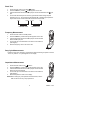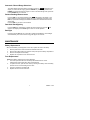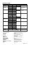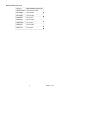
1
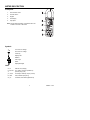
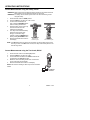
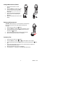
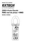
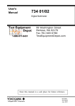
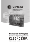
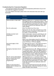
User's Manual
2000A Auto Ranging
True RMS Clamp + DMM
MODEL 380926
INTRODUCTION
Congratulations on your purchase of Extech’s 380926 Clamp meter + Digital MultiMeter. This
meter can measure to 2000A through the clamp and also measure to 400mA through the test
leads. With Capacitance, Diode and Duty Cycle measurements, this meter provides the user
with a full featured multimeter combined with the high amperage current clamp. This meter is
shipped fully tested and calibrated and, with proper use, will provide years of reliable service.
SAFETY
Safety Symbols
This symbol, adjacent to another symbol or terminal, indicates the user must
refer to the manual for further information.
This symbol, adjacent to a terminal, indicates that, under normal use,
hazardous voltages may be present
Double insulation
WARNING: This indicates that a potentially hazardous condition which, if not avoided,
could result in death or serious injury.
CAUTION: This indicates that a potentially hazardous condition which, if not avoided,
could result in injury or damage to the meter Reply to request.
Safety Precautions
1.
WARNING: Improper use of this meter can cause damage, shock, injury or death.
Read and understand this user’s manual before operating the meter.
2.
Make sure any covers or battery doors are properly closed and secured.
3.
Always remove the test leads before replacing the battery or fuses.
4.
Inspect the condition of the test leads and the meter itself for any damage before
operating the meter. Repair or replace any damage before use.
5.
Do not exceed the maximum rated input limits.
6.
Use great care when making measurements if the voltages are greater than 25VAC
rms or 35VDC. These voltages are considered a shock hazard.
7.
Always discharge capacitors and remove power from the device under test before
performing Capacitance, Diode, Resistance or Continuity tests.
8.
Remove the battery from the meter if the meter is to be stored for long periods.
2
380926 4.1 07/07
METER DESCRIPTION
Front panel
1.
Current Sense Jaws
2.
Function switch
3.
Keypad
4.
LCD display
5.
Input jacks
Note: The tilt stand and battery compartment door are
located on the rear of the meter.
Symbols
AC current or Voltage
DC current or Voltage
Continuity
H
Display hold
REL
Relative
AUTO
Auto range
Diode
Display Backlight
Units
mV, V
Ω, kΩ, MΩ
%
μA, mA, A
Hz, kHz
nF, μF
millivolt, volt (voltage)
ohm, kilohm, megohm (resistance)
percent (duty cycle)
microamps, milliamps, amps (current)
hertz, kilohertz (frequency)
nanofarad, microfarad (capacitance)
3
380926 4.1 07/07
OPERATING INSTRUCTIONS
Current Measurements using the Clamp, DC/AC
WARNING: Make sure that the test leads are disconnected from the meter’s terminals
before making current measurements with the clamp jaw.
WARNING: For safety, use the rubber input terminal cover when measuring current
using the Clamp.
1.
2.
3.
4.
5.
6.
Set the Function switch to 2000A position.
Press the FUNC key to select AC or DC current
For DC current measurements,
push & hold the DCA ZERO button
until the reading indicates zero.
Press the trigger to open jaw. Fully
enclose the conductor to be
measured (see diagram).
The clamp meter will automatically
select the proper range (Auto
Range). To select the range
manually, press the RANGE button
before pressing DCA ZERO button.
INCORRECT
Read the measured value from the
More than one
LCD display.
conductor in jaws
CORRECT
One conductor in jaws
NOTE: If the DCA zero button is used to zero the meter, the clamp meter remains in the
auto-range mode. If the REL button is used, the clamp meter will be placed in the
manual range mode.
Current Measurements using the Test Leads, DC/AC
1.
2.
3.
4.
5.
Set the Function switch to the mA or µA position.
Press the FUNC key to select AC or DC.
Connect the black test lead to the COM terminal and the
red test lead to the mA µA input jack.
Break the circuit under test (put the meter in series with
circuit under test) refer to diagram.
Read the measured value from the LCD display.
NOTE: The maximum reading for direct input current is 240mA
AC/DC.
µA and mA
Current
4
380926 4.1 07/07
Voltage Measurements, DC/AC
1.
2.
3.
4.
5.
Set the Function Switch to the V
position.
Press the FUNC key to select AC or DC.
Insert the black test lead to the COM
input jack and the red test lead into the
V input jack.
Connect the test leads in PARALLEL
with the circuit to be measured (see
diagrams).
Read the measured value from the LCD
display.
Resistance Measurements
CAUTION: Before taking any in-circuit resistance measurements
remove power from the circuit under test and discharge all
capacitors.
1. Set the Function switch to the Ω position.
2. Press the FUNC key until the ohms symbol appears on LCD.
3. Insert the black test lead to the COM input jack and the red
test lead to the Ω input jack.
4. Connect test leads to the device under test (see diagram).
5. Read the measured value from the LCD display.
Continuity Test
1.
2.
3.
4.
5.
6.
Set the Function switch to the
position.
Press the FUNC key until the "Ω" and " " symbols appear on the display.
Insert the black test lead to the COM input jack and the red test lead to the Ω input
jack.
Connect the test lead tips to the device to be measured (refer to diagram for
resistance measurements above).
Read the measured value from the LCD display.
If the resistance is < 10Ω approx. an audible signal will be heard.
5
380926 4.1 07/07
Diode Test
1.
2.
3.
4.
Set the Function switch to the diode
position.
Press the FUNC key until the
symbol appears on the LCD.
Insert the black test lead to the COM input jack and the red test lead to the
input
jack.
Connect the test lead tips to the diode. A typical diode forward voltage drop will
indicate 0.3 to 0.7V. The reverse drop will indicate "OL", indicating high impedance.
Proper diode check should include both forward and reverse tests.
RED
BLACK
BLACK
FORWARD TEST
RED
REVERSE TEST
Frequency Measurement
1.
2.
3.
4.
5.
Set the Function switch to the Hz position.
Press the FUNC key until the "Hz" symbol appears on the LCD.
Insert the black test lead to the COM input jack and the red test
lead to the Hz input jack.
Connect the tips of the test leads to the device to be measured
(see diagram).
Read the frequency value in Hz on the LCD.
Duty Cycle Measurements
Follow the steps as for Frequency measurements with the following exception: Press the
“Hz/%” key until the “%” symbol appears on the display.
Capacitance Measurement
1.
2.
3.
4.
5.
Set the Function switch to the
position.
Press the FUNC key until the "nF" symbol appears on the LCD.
Insert the black test lead to the COM input jack and the red test
lead to the red input terminal.
Connect the tips of the test leads to the device to be measured
(see diagram).
Read the capacitance value on the display.
NOTE: When making very low capacitance measurements, use the
REL function to zero any stray capacitance.
6
380926 4.1 07/07
Automatic / Manual Range Selections
The meter defaults to the autoranging mode when turned on. "AUTO" will appear in the
display. To select manual ranging, press the RANGE key. Momentary presses of the
RANGE key will step through the ranges. To return to the Auto Range mode, press and
hold the RANGE key for 2 seconds.
Relative Reading Measurements
Press the REL key to enter the relative mode. "REL" will appear in the display. In the
relative mode, the meter stores the reading that was on the display at the time of the
REL key is pressed and displays the difference between the measured value and the
stored value
Press the REL key to return to normal mode.
Data Hold / Backlight key
Press the HOLD key momentarily to freeze the present reading on the LCD."H" will
appear in the display. Press HOLD again to return to normal operation.
Backlight
Press and hold the Hold key for 2 seconds to activate the backlighting. The backlight
will automatically turn off to conserve energy after approx 12 seconds.
MAINTENANCE
Battery Replacement
When the low battery symbol appears on the LCD, replace the meter’s 9V battery.
1. Remove power to the meter and remove test leads from meter
2. Remove the Phillips head screw (back of meter) and open the battery compartment.
3. Remove and replace the 9V battery.
4. Replace the compartment cover and rear screw.
Fuse Replacement
NOTE: Fuse Rating: 500mA (5mm x 20mm diameter)
1. The meter is provided with one overload protect 500mA fuse for current
measurements (direct input NOT clamp measurements).
2. To replace the fuse, open the meter case by removing the battery cover and battery
and then the four screws holding the rear case.
3. The fuse is located on the Main PCB.
4. Replace fuse and secure meter case.
7
380926 4.1 07/07
SPECIFICATIONS
Function
AC/DC Current
(Clamp on)
AC Voltage
True RMS
DC Voltage
Resistance
AC/DC Current
(Direct Input)
Frequency
Capacitance
Duty Cycle
Continuity
Range
Resolution
Accuracy
400.0A
0.1A
±(2.0% + 5d)
2000A
1A
±(2.0% + 8d)
4.000V
1mV
±(1.2% + 5d)
40.00V
10mV
400.0V
0.1V
1000V
1V
400.0mV
0.1mV
±(0.5% + 2d)
±(1.0% + 2d)
4.000V
1mV
40.00V
10mV
400.0V
0.1V
1000V
1V
±(1.0% + 5d)
400.0 Ω
0.1Ω
4.000 kΩ
1Ω
40.00 kΩ
10Ω
400.0 kΩ
100Ω
±(2.0% + 2d)
4.000 MΩ
1kΩ
±(3.5% + 5d)
40.00 MΩ
10kΩ
400.0µA
0.1µA
±(1.2% + 5d)
4000µA
1µA
40.00mA
0.01mA
400.0mA
0.1mA
5Hz
0.001Hz
±(1% + 5d)
50Hz
0.01Hz
500Hz
0.1Hz
5kHz
1Hz
50kHz
10Hz
100kHz
100Hz
50nF
10pF
±(3% + 5d)
500nF
100pF
5µF
0.001µF
50µF
0.01µF
1 to 99%
0.1%
±(1% + 5d)
Audible tone; <10 ohms approximately
Open circuit voltage; 0.5V approximately
Conductor Size
Measurement parameters
Current Sensor
Zero adjust
Diode Test
Battery type
Range Selection
Display
Overload Indication
Power Consumption
Low Battery Indication
Sampling rate
Standards
Operating Temperature/Humidity
Dimensions
Weight
Remarks
45Hz to 1KHz
45Hz to 1KHz
Input Impedance:
10Mohms
Input Impedance:
10Mohms
45Hz to 1KHz
Accuracy stated
after a relative "REL"
zero performed
60mm (2.36”) maximum
ACA, DCA, ACV, DCV, Resistance, Diode, Frequency,
Capacitance, Duty Cycle, Continuity
Hall Effect
Automatic except for DCA (Push-button)
Test current of 0.6mA typical;
Open circuit voltage <1.6V DC typical.
9V NEDA 1604
Auto or manual
0.6” (15mm) 5000 Count Backlit LCD
"OL"
5mA approx.
Battery icon appears on LCD
1 reading every 0.35 seconds approx.
CE, IEC 1010-1 CAT IV 600V
32 to 122oF (0oC to 50oC) / <80%
10 x 2.9 x 1.5” (255 x 73 x 38mm)
0.85 lbs. (380g)
8
380926 4.1 07/07
Maximum Rated Input Limits
Function
Maximum Rated Input Limits
AC/DC Current
500mA AC/DC (fused)
AC Voltage
1000 VAC/DC
DC Voltage
1000 VAC/DC
Resistance
400 VAC/DC
Frequency
1000 VAC/DC
Capacitance
400 VAC/DC
Duty Cycle
1000 VAC/DC
Diode Test
400 VAC/DC
9
380926 4.1 07/07
Warranty
EXTECH INSTRUMENTS CORPORATION warrants this instrument to be free of defects
in parts and workmanship for one year from date of shipment (a six month limited warranty
applies to sensors and cables). If it should become necessary to return the instrument for
service during or beyond the warranty period, contact the Customer Service Department at
(781) 890-7440 ext. 210 for authorization or visit our website www.extech.com for contact
information. A Return Authorization (RA) number must be issued before any product is
returned to Extech. The sender is responsible for shipping charges, freight, insurance and
proper packaging to prevent damage in transit. This warranty does not apply to defects
resulting from action of the user such as misuse, improper wiring, operation outside of
specification, improper maintenance or repair, or unauthorized modification. Extech
specifically disclaims any implied warranties or merchantability or fitness for a specific
purpose and will not be liable for any direct, indirect, incidental or consequential damages.
Extech's total liability is limited to repair or replacement of the product. The warranty set
forth above is inclusive and no other warranty, whether written or oral, is expressed or
implied.
Calibration and Repair Services
Extech offers repair and calibration services for the products we sell. Extech also
provides NIST certification for most products. Call the Customer Care Department for
information on calibration services available for this product. Extech recommends that
annual calibrations be performed to verify meter performance and accuracy.
Support line (781) 890-7440
Technical support: Extension 200; E-mail: [email protected]
Repair & Returns: Extension 210; E-mail: [email protected]
Product specifications subject to change without notice
For the latest version of this User’s Guide, Software updates, and other
up-to-the-minute product information, visit our website: www.extech.com
Extech Instruments Corporation, 285 Bear Hill Rd., Waltham, MA 02451
Copyright © 2007 Extech Instruments Corporation
All rights reserved including the right of reproduction in whole or in part in any form.
10
380926 4.1 07/07