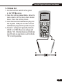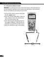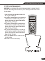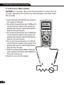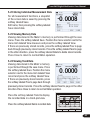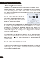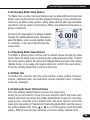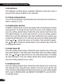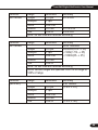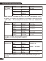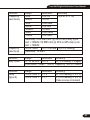
1
MT-1007
True-RMS Digital Multimeter
User Manual
True-RMS Digital Multimeter
11
True-RMS Digital Multimeter User Manual
True-RMS Digital Multimeter User Manual
Contents
1.Introduction....................................................................................... 4
2.Safety................................................................................................ 4
3.Safety Instructions............................................................................. 6
4.Feature.............................................................................................. 7
5.Measurement and Setup.................................................................... 11
6.General Specifications.........................................................................32
7.Specifications.................................................................................... 34
3
True-RMS Digital Multimeter User Manual
1.Introduction
This meter measures AC/DC Voltage, AC/DC Current, Resistance,Capacitance,
Frequency(electrical & electronic), Duty Cycle, Diode Test,Insulation Test,and
Continuity plus Thermocouple Temperature. It can store and recall data.
It features a waterproof, rugged design for heavy duty use.
Proper use and care of this meter will provide many years of reliable service.
2.Safety
This symbol adjacent to another symbol, terminal or operating device
indicates that the operator must refer to an explanation in the Operating
Instructions to avoid personal injury or damage to the meter.
WARNING This WARNING symbol indicates a potentially hazardous
situation, which if not avoided, could result in death or serious
injury.
CAUTION This CAUTION symbol indicates a potentially hazardous
situation, which if not avoided, may result damage to the
product.
MAX
This symbol advises the user that the terminal(s) so marked must not
be connected to a circuit point at which the voltage with respect to earth
ground exceeds (in this case) 1000 VAC or VDC.
This symbol adjacent to one or more terminals identifies them as being
associated with ranges that may, in normal use, be subjected to
particularly hazardous voltages. For maximum safety, the meter and its
test leads should not be handled when these terminals are energized.
This symbol indicates that a device is protected throughout by double
insulation or reinforced insulation.
4
True-RMS Digital Multimeter User Manual
PER IEC1010 OVERVOLTAGE INSTALLATION CATEGORY
OVERVOLTAGE CATEGORY I
Equipment of OVERVOLTAGE CATEGORY I is equipment for connection to
circuits in which measures are taken to limit the transient overvoltages to an
appropriate low level.
Note – Examples include protected electronic circuits.
OVERVOLTAGE CATEGORY II
Equipment of OVERVOLTAGE CATEGORY II is energy-consuming equipment
to be supplied from the fixed installation.
Note – Examples include household, office, and laboratory appliances.
OVERVOLTAGE CATEGORY III
Equipment of OVERVOLTAGE CATEGORY III is equipment in fixed installations.
Note – Examples include switches in the fixed installation and some equipment
for industrial use with permanent connection to the fixed installation.
OVERVOLTAGE CATEGORY IV
Equipment of OVERVOLTAGE CATEGORY IV is for use at the origin of the
installation.
Note – Examples include electricity meters and primary over-current protection
equipment
5
True-RMS Digital Multimeter User Manual
3.Safety Instructions
This meter has been designed for safe use, but must be operated with caution.
The rules listed below must be carefully followed for safe operation.
3-1.NEVER apply voltage or current to the meter that exceeds the specified
maximum:
Input Protection Limits
Maximum Input
1000VDC/AC RMS
500mA 1000V fast acting fuse
10A 1000V fast acting fuse
(20A for 30 seconds max every
15 minutes)
Frequency, Resistance, Capacitance,
1000VDC/AC rms
Duty Cycle, Diode Test, Continuity
Temperature
1000VDC/AC rms
Surge Protection: 8kV peak per IEC 61010
Function
V DC or V AC
mA AC/DC
A AC/DC
3-2.USE EXTREME CAUTION when working with high voltages.
3-3.DO NOT measure voltage if the voltage on the “COM” input jack exceeds
1000V above earth ground.
3-4.NEVER connect the meter leads across a voltage source while the
function switch is in the current, resistance, or diode mode. Doing so can
damage the meter.
3-5.ALWAYS discharge filter capacitors in power supplies and disconnect
the power when making resistance or diode tests.
3-6.ALWAYS turn off the power and disconnect the test leads before opening
the covers to replace the fuse or batteries.
6
True-RMS Digital Multimeter User Manual
3-7.NEVER operate the meter unless the back cover and the battery and fuse
covers are in place and fastened securely.
If the equipment is used in a manner not specified by the manufacturer, the
protection provided by the equipment may be impaired.
4.Feature
4-1.Understanding the Push Buttons
The 12 push buttons on the front of the Meter
activate features that augment the function
selected using the rotary switch, navigate
menus or control power to Meter circuits.
F1F2F3F4 Selects sub-functions and modes related to the rotary switch
function.
Cursor buttons select an item in a menu, adjust display contrast, scroll
through information, and perform data entry.
HOLD Freezes the present reading in the display and allows the display to be
saved. Also accesses AutoHold.
RANGES witches the Meter range mode to manual and then cycles through all
ranges. To return to auto ranging, press the button for 1 second.
MAX/MIN Starts and stops MIN MAX recording.
Switch the display backlight
7
True-RMS Digital Multimeter User Manual
4-2.Understanding the Display
7
8
9
10
8:10pm
6
auto range
11
123.45VAC
12
06/13/07
RE L
VAC
13
123.45
5
4
3
0
100
200
300
400
500 VAC
2
48 .65 dBm
14
1
1-Soft key labels Indicates the function of the button just below the displayed
label.
2-Bar graph Analog display of the input signal (See the “Bar Graph” section
for more information).
3-Relative Indicates the displayed value is relative to a reference value.
4-Minus sign Indicates a negative reading.
5-Remote communication Indicates activity over the communication link.
6-Indicates the range the Meter is in and the ranging mode (auto or manual)
7-Battery level Indicates the charge level batteries.
8-Time Indicates the time set in the internal clock.
9-Mode annunciators Indicates the Meter’s mode.
10-Minimeasurement Displays the lightning bolt (when necessary) and the
input value when the primary and secondary displays are covered by a
menu or pop-up message.
11-Date Indicates the date set in the internal clock.
12-Beeper Indicates the Meter’s beeper is enabled (not associated with the
continuity beeper).
13-Units Indicates the units of measure.
14-Secondary display Displays secondary measurement information about
the input signal.
8
True-RMS Digital Multimeter User Manual
4-3.Bar Graph
The analog bar graph functions like the needle on an analog meter, but without
the overshoot. For frequency, duty cycle, pulse width, dBm, and crest factor
functions, the bar graph represents the amplitude of the input signal (volts or
amps) and not the value in the primary display. The bar graph is not shown
for capacitance, temperature, AC+DC, AC over DC, peak, or min max
functions. For DC voltage, DC current, and all relative percent modes, a
zero-centered bar graph is displayed. For DC voltage and current, the bar graph
range is the maximum of the selected range. For relative percent mode, the
bar graph goes to ±10 %. The number of lit segments indicates the measured
value and is relative to the full-scale value of the selected range. In the 50 VAC
range, for example, the major divisions on the scale represent 0, 5, 10, 15,
20, 25, 30, 35, 40, 45, and 50 VAC. An input of 25 VAC turns on segments
up to the middle of the scale.
4-4.Page Area
The page area of the display is where the main meter content is displayed.
The primary display (upper half of the page area) is where the most important
value of the selected function is shown. The secondary display contains the
bar graph and values that may be measured in addition to the primary function
value. For example, with frequency measurement selected in Vac, the frequency
value will appear in the primary display with the ac voltage value in the
secondary display.
4-5.Softkey Labels
Labels for the four function softkeys (F1 through F4) appear in the bottom row
of the display. These labels will change based on the function and/or menu
selection.
9
True-RMS Digital Multimeter User Manual
4-6.Understanding the Rotary Switch
Select a primary measurement function
by positioning the rotary switch to one of
the icons around its perimeter. For each
function, the Meter presents a standard
display for that function (range, measurement units, and modifiers). Button
choices made in one function do not carry over into another function.
DC(AC) and AC+DC voltage measurements
AC voltage measurements
DC(AC) millivolts, ac+dc millivolt measurements
Frequency measurements
Resistance, Diode test, Capacitance and Continuity measurements
Temperature measurements
AC, DC and AC+DC amps measurements
AC, DC and AC+DC milliamps measurements
AC, DC and AC+DC microampere measurements up to 5,000μA
4-7.Using the Input Terminals
All functions except current use the VOHMS
and COM input terminals. The two current
input terminals (A and mA/μA) are
Used as follows:
Current from 0 to 500 mA, use the uAmA and COM terminals.
Current between 0 and 10 A use the A and COM terminals.
Input for 0 A to 10.00 A current (20VA overload for 30 seconds
on, 10 minutes off),
Input for 0 A to 500 mA current measurements.
Return terminal for all measurements.
Input for voltage, continuity, resistance, diode test, conductance,
capacitance.
10
True-RMS Digital Multimeter User Manual
5. Measurement and Setup
5-1.DC Voltage Measurements
CAUTION: Do not measure DC voltages if a motor on the circuit is being
switched ON or OFF. Large voltage surges may occur that can damage the
meter.
8: 10 pm
06 /1 3/ 07
auto range
1.Set the function switch to the green VDC
position.
2.Insert the black test lead banana plug
into the negative COM jack. Insert the
red test lead banana plug into the positive
V jack.
3.Read the voltage in the display.
VDC
100.00
0
100
200
300
400
500 VDC
11
True-RMS Digital Multimeter User Manual
5-2.AC Voltage Measurements
WARNING: Risk of Electrocution. The probe tips may not be long enough to
contact the live parts inside some 240V outlets for appliances because the
contacts are recessed deep in the outlets. As a result, the reading may show
0 volts when the outlet actually has voltage on it. Make sure the probe tips
are touching the metal contacts inside the outlet before assuming that no
voltage is present.
CAUTION: Do not measure AC voltages if a motor on the circuit is being
switched ON or OFF. Large voltage surges may occur that can damage the
meter.
1.Set the function switch to the green VAC
position.
2.Insert the black test lead banana plug into
the negative COM jack. Insert red test lead
banana plug into the positive V jack.
3.Read the voltage in the main display
12
8: 10 pm
06 /1 3/ 07
auto range
VAC
100.00
0
100
200
300
400
500 VAC
True-RMS Digital Multimeter User Manual
5-3.Making dB Measurements
The Meter is capable of displaying voltage as a dB value, either relative to 1
milliwatt (dBm), a reference voltage of 1 volt (dBV) or a user-selectable
reference value.
1.Set the function switch to the green VAC
position.
2.press the softkey labeled Menu. Move the
menu selector to the menu item labeled
dBm. Press the softkey dBm
3.Insert the black test lead banana plug into
the negative COM jack. Insert red test lead
banana plug into the positive V jack.
4.Read the voltage in the main display and the dBm in the Secondary display
5.To select another reference value, press the softkey labeled Ref to display
a message box with the current reference value. Pressing or , scrolls
through the nine predefined references: 4,8,16,25,32,50,75,600 and 1000.
Set the reference by pressing the softkey labeled OK.
5-4.Low Pass Filter
The Meter is equipped with an ac low pass
filter. When measuring ac voltage, press the
soft key labeled Menu to open the function
menu, and move the menu selector to the LO
item. Next, press the softkey labeled LO to
toggle the low pass filter mode .
13
True-RMS Digital Multimeter User Manual
5-5.mV Voltage Measurements
CAUTION: Do not measure mV voltages if a motor on the circuit is being
switched ON or OFF. Large voltage surges may occur that can damage the
meter.
1.Set the function switch to the green mV
position.
2.Press the soft key labeled Menu.
Move the menu selector to the menu item
labeled mVDC(mVAC). Press the soft key
mVDC(mVAC).
3.Insert the black test lead banana plug into
the negative COM jack. Insert the red test
lead banana plug into the positive V jack.
4.Read the mV voltage in the display
14
8: 10 pm
06 /1 3/ 07
auto range
mVAC
500.00
0
100
200
300
400
500 mVAC
True-RMS Digital Multimeter User Manual
5-6.Temperature Measurements
1.Set the function switch to the green
TEMP(°C or °F) position.
2.Insert the Temperature Probe into the input
jacks, making sure to observe the correct
polarity.
3.Read the temperature in the display
4.To input a temperature offset value, press
the softkey labeled Offset to open a message
box with the present offset value.
Use and to position the cursor over
one of the digits or the polarity sign.
Use and to scroll through the numbers
for each digit in the offset or switch between
a + or – offset. With the desired value
displayed, press the softkey labeled OK to
set the temperature offset.
8: 10 pm
auto range
100.00
06 /1 3/ 07
°C
15
True-RMS Digital Multimeter User Manual
5-7.Frequency Measurements
1.Set the function switch to the green Hz%
position.
2.Insert the black test lead banana plug into
the negative COM jack. Insert the red test
lead banana plug into the positive V jack.
3.Read the Frequency in the display
16
8: 10 pm
06 /1 3/ 07
auto range
50.000
0.00%
Hz
True-RMS Digital Multimeter User Manual
5-8.Resistance Measurements
WARNING: To avoid electric shock, disconnect power to the unit under test
and discharge all capacitors before taking any resistance measurements.
Remove the batteries and unplug the line cords.
1.Set the function switch to the green
Ω CAP
position.
2.Insert the black test lead banana plug into
the negative COM jack. Insert the red test
lead banana plug into the positive Ω Jack.
3.Read the resistance in the display.
8: 10 pm
auto range
50.000
06 /1 3/ 07
MΩ
17
True-RMS Digital Multimeter User Manual
5-9.Continuity Check
WARNING: To avoid electric shock, disconnect power to the unit under test
and discharge all capacitors before taking any resistance measurements.
Remove the batteries and unplug the line cords.
1.Set the function switch to the green
Ω CAP
position.
2.Press the soft key labeled Menu. Move the
menu selector to the menu item labeled
Beeper. Press the soft key Beeper.
3.Insert the black test lead banana plug into
the negative COM jack. Insert the red test
lead banana plug into the positive jack.
4.If the resistance is less than approximately
25Ω, the audible signal will sound. If the
circuit is open, the display will indicate “OL”.
18
8: 10 pm
auto range
25.000
06 /1 3/ 07
Ω
True-RMS Digital Multimeter User Manual
5-10.Diode Test
1.Set the function switch to the green
Ω CAP
position.
2.Press the soft key labeled Menu. Move the
menu selector to the menu item labeled
Diode. Press the soft key Diode.
3.Insert the black test lead banana plug into
the negative COM jack and the red test
lead banana plug into the positive V jack.
5.Forward voltage will typically indicate
0.400 to 3.200V. Reverse voltage will
indicate “OL”. Shorted devices will indicate
near 0V and an open device will indicate
“OL” in both polarities.
8: 10 pm
auto range
06 /1 3/ 07
V
0.400
19
True-RMS Digital Multimeter User Manual
5-11.Capacitance Measurements
WARNING: To avoid electric shock, disconnect power to the unit under test
and discharge all capacitors before taking any capacitance measurements.
Remove the batteries and unplug the line cords.
1.Set the rotary function switch to the green
Ω CAP
position.
2.Press the soft key labeled Menu. Move the
menu selector to the menu item labeled
Cap. Press the soft key Cap.
3.Insert the black test lead banana plug into
the negative COM jack. Insert the red test
lead banana plug into the positive V jack.
4.Read the capacitance value in the Display
20
8: 10 pm
auto range
10.00
06 /1 3/ 07
mF
True-RMS Digital Multimeter User Manual
5-12.DC Current Measurements
CAUTION: Do not make 20A current measurements for longer than 30
seconds. Exceeding 30 seconds may cause damage to the meter and/or
the test leads.
1.Insert the black test lead banana plug into
the negative COM jack.
2.For current measurements up to 5000µA DC,
set the function switch to the yellow µA
position and insert the red test lead banana
plug into the µA/mA jack.
3.For current measurements up to500mA DC,
set the function switch to the yellow mA
position and insert the red test lead banana
plug into the µA/mA jack.
4.For current measurements up to 10A DC,
set the function switch to the yellow 10A
position and insert the red test lead banana
plug into the 10A jack.
5.Press the MODE button to indicate “DC”
on the display.
6.Read the current in the display.
8: 10 pm
06 /1 3/ 07
auto range
ADC
10.000
0
100
200
300
400
500 ADC
21
True-RMS Digital Multimeter User Manual
5-13.AC Current Measurements
CAUTION: Do not make 10A current measurements for longer than 30
seconds. Exceeding 30 seconds may cause damage to the meter and/or
the test leads.
1.Insert the black test lead banana plug into
the negative COM jack.
2.For current measurements up to 5000µA AC,
set the function switch to the yellow µA
position and insert the red test lead banana
plug into the µA/mA jack.
3.For current measurements up to 500mA AC,
set the function switch to the yellow mA
position and insert the red test lead banana
plug into the µA/mA jack.
4.For current measurements up to 20A AC,
set the function switch to the yellow 10A
position and insert the red test lead banana
plug into the 10A jack.
5.Press the soft key labeled Menu. Move the
menu selector to the menu item labeled AC.
Press the soft key AC.
6.Read the current in the display
22
8: 10 pm
06 /1 3/ 07
auto range
AAC
10.000
0
100
200
300
400
500 AAC
True-RMS Digital Multimeter User Manual
5-14.Understanding Function Menus
Each primary measurement function (rotary switch position) has a number
of optional sub-functions or modes accessed by pressing the softkey labeled
Menu (F1). A typical menu is shown in Figure.
Menu selection is indicated by the filled-in
black square(hereafter the menu selector)
to the left of a menu item. Use the four
front-panel cursor buttons (
) to
position the menu selector next to a menu
item. As the menu selector moves between
menu items, the four softkeys and their labels
change to reflect the available functions
and/or modes available for the selection
menu item.
5-15.Using Help
While operating the Meter, more information about a selected function, a
front-panel button, or a menu item may be necessary. Press soft key HELP
to open an information window that lists topics covering the functions and
modifiers that are available at the time the button is pressed. Each topic
provides a brief explanation on a Meter function or feature.
The number of information topics displayed at any one time may exceed the
display area. Use the softkeys labeled Next and Prev to move from topic to
topic. Use the softkey labeled More or and to scroll through the
information a full screen at a time.
23
True-RMS Digital Multimeter User Manual
5-16.Measuring AC and DC Signals
The Meter is capable of displaying both AC and DC signal components (voltage
or current) as two separate readings or one AC+DC(RMS) value combined.
As shown in Figure , the Meter displays ac and dc combinations two ways:
DC displayed over AC (DC,AC), and AC combined with dc (AC+DC). Select
one of these three displays using the Function and Mode menu.
With the rotary switch set to V, mV, A, mA,or uA, press the soft key labeled
Menu. Move the menu selector to the menu item labeled AC+DC. At this point,
three different soft key labels indicate AC+DC (F1),and DC,AC (F2). Press
the soft key that presents these two signals as needed. While in any of the
three AC+DC modes, peak measurements, frequency, duty cycle, relative %,
and period measurements are not allowed. In addition to these modes, MIN
MAX, relative.
24
True-RMS Digital Multimeter User Manual
5-17.Capturing Minimum and Maximum Values
The MAX MIN Record mode captures minimum, average, and maximum input
values. When the input goes below the recorded minimum value or above the
recorded maximum value, the Meter beeps and records the new value. The
Meter stores the elapsed time since the recording session was started at the
same time. The MAX MIN mode also calculates an average of all readings
taken since the MAX MIN mode was activated. This mode is for capturing
intermittent readings,recording minimum and maximum readings unattended,
or recording readings while equipment operation precludes watching the Meter.
The MIN MAX mode is best for recording power supply surges, inrush currents,
and finding intermittent failures. Response time is the length of time an input
must stayat a new value to be captured as a possible new minimumor
maximum value.
To activate the MAX MIN mode, press MAX MIN. As shown in Figure, the
Meter displays e at the top of the measurement page, and the MAX MIN start
date and time along the bottom of the page. In addition, the recorded maximum,
average, and minimum values appear in the secondary display with their
respective elapsed times.
To stop a MIN MAX recording session, press
the softkey labeled Stop. The summary
information in the display freezes, and the
softkeys change function to allow saving
the collected data. Pressing the softkey
labeled Close exits the MIN MAX record
session without saving the collected data.
To save the MIN MAX screen data, the MIN MAX session must be ended by
pressing the softkey labeled Stop. Next, press the softkey labeled Save.A
dialog box openswhere the default saved name can be selected or anothername
assigned. the softkey labeled Save to store. Pressing the softkey labeled
Restart while MIN MAX is running stops the MIN MAX session, discards all
MIN MAXdata, and immediately starts a new MIN MAX recording session.
25
True-RMS Digital Multimeter User Manual
5-18.Capturing Peak Values
To activate the peak mode, press the softkey
labeled Menu.Move the menu selector next
to the menu item labeledPeak, CF or Peak.
Press the softkey labeled Peak to startthe
peak recording session.
5-19.Relative Values
To activate the peak mode, press the softkey labeled Menu. Move the menu
selector next to the menu item labeled REL or Peak. Press the softkey labeled
REL to start the peak recording session.
If the Meter is already in the relative function, pressing Rel% causes the Meter
to turn off relative and display relative percent.
5-20.Low Pass Filter
The Meter is equipped with an ac low pass
filter. When measuring AC voltage, press the
softkey labeled Menu to open the function
menu, and move the menu selector to the
LO item. Next, press the softkey labeled LO
to toggle the low pass filter mode.
03/26/11
13:25
5-21.Hold and AutoHold Mode
Auto Range
Hold
To freeze the display for any function, press
key HOLD.
Pressing the softkey labeled AutoHOLD
activates AutoHold if the Meter is not in the
AUTOHOLD
SAVE
SETUP
Peak, MIN MAX, or Record modes. AutoHold
operation monitors the input signal and updates the display and, if enabled,
sounds the beeper, whenever a new stable measurement is detected. A stable
measurement is one that does not vary more than a selected adjustable
percentage (AutoHold threshold) for at least one second. The Meter filters
out open lead conditions so the Meter leads can be moved between test
points without triggering a display update.
0 000
-50 -40 -30 -20 -10
26
0
10
20
30
40 50mADC
True-RMS Digital Multimeter User Manual
5-22.Storing Individual Measurement Data
For all measurement functions, a snapshot
of the screen data is saved by pressing the
softkey labeled Save.
Edit name, then pressing the softkey labeled
Save stored date.
5-23.Viewing Memory Data
Viewing data stored in the Meter’s memory is performed through the save
menu. Press the softkey labeled Save. Position the menu selector next to the
menu item labeled View measure and press the softkey labeled View.
If there are previously stored records, press the softkey labeled Prev to page
back through previously stored records. Press the softkey labeled Next to page
in the other direction. press the softkey labeled Delete to delete stored records.
Press Close to return to normal Meter operation.
5-24.Viewing Trend Data
Viewing data stored in the Meter’s memory
is performed through the save menu. Press
the softkey labeled Save. Position the menu
selector next to the menu item labeled View
record and press the softkey labeled View.
If there are previously stored records, press
the softkey labeled Prev to page back through
previously stored records. Press the softkey labeled Next to page in the other
direction.Press Close to return to normal Meter operation.
Press the soft key labeled Trend to display
the recorded data in a trend-plot view.
Press the softkey labeled Delete recorded data
13:22
15
9.0
3.0
0
3.0
9.0
15
00:00
03/26/11
VDC
00:15
DELETE
03/26/11 13:20:53
00:30
00:45
01:00
0.0003 vdc 13:21:14
CLOSE
SUMMARY
27
True-RMS Digital Multimeter User Manual
5-25.Recording Measurement Data
The Meter’s record feature collects measurement information over a
user-specified duration. This collection of information is called a recording
session. A recording session is made up of one or more measurement records
Each record contains measurement summary information covering the
duration of the record.
Press the softkey labeled Save. Position the
menu selector next to the menu item labeled
Record and press the softkey labeled Record
to open the configuration display.
Recording session duration,and sample interval duration.Both variables affect
the recording length and number of intervals recorded. These two variables
may interact, in that setting one variable may adjust the other variable to fit
the recording session within the available memory. The percentage of memory
available at the beginning of a recording session is displayed below the duration
and sample interval settings.
To change either of the two recording variables, use the cursor buttons to
position the menu selector next to the desired menu item and press the softkey
labeled Edit. Use
and to move between and set each digit of the
selected variable.
Press the softkey labeled Start to start records.
The recording session will continue until the allocated memory is used, the
batteries expire, the rotary switch is moved. or the session is terminated by
pressing the softkey labeled Stop.
28
True-RMS Digital Multimeter User Manual
5-26.Changing Meter Setup Options
The Meter has a number of preset features such as date and time formats and
battery save mode timeouts, and the displayed language. These variables are
referred to as Meter setup options. Many setup options affect general Meter
operations and are active in all functions. Others are limited toone function or
group of functions.
Access to the setup options is always available
through the softkey labeled Setup. Information
about the Meter, such as serial number, model,
for example. is also accessed through the
setup menu.
5-27.Resetting Meter Setup Options
The Meter’s setup options can be reset to default values through the setup
menu. Open the setup menu by pressing the softkey labeled Setup. Position
the menu selector next to the menu item labeled Reset and press the softkey
labeled Setup. A message will appear asking to confirm the reset action.
Press the softkey labeled OK to perform the reset.
5-28.Meter Info
The Meter Info selection lists the serial number, model number, firmware
version, calibration date, and calibration counter. Operator name, company
name are displayed.
5-29.Setting the Event Threshold Value
Press the softkey labeled Setup to access the setup menu.
Using the cursor buttons, move the menu selector next to the menu item
labeled Instrument and press the softkey labeled Enter to open the recording
setup screen. Using the cursor buttons,move the menu selector next to the
menu item labeled Event Threshold for Recording(AutoHOLD) and then press
the softkey labeled Edit. Press or to scroll through the event threshold
values. With the desired value selected, press the softkey labeled Close.
29
True-RMS Digital Multimeter User Manual
5-30.Calibration
The Calibration selection allows a qualified calibration technician to enter a
password that allows the Meter to be calibrated.
5-31.Using Communications
You can use the Wireless communication link and transfer the contents of a
meter’s memory to a PC.
5-32.Setting Date and Time
The Meter’s internal clock is used in the display and for timestamping recorded
measurements. To change the date and time as well as the display format,
press the softkey labeled Setup. Position the menu selector next to the menu
item labeled Display. To set the date and time, press the softkey labeled
Date/Time to open the date/time menu. Next, position the menu selector next
to either the Set Date item or Set Time item and press the softkey labeled Edit.
Using and , position the cursor on the date or time element to adjust.
Use and to change the selected date or time element value. Press OK
to complete the action.
5-33.Auto Power Off
Press the softkey labeled Setup. Position the menu selector next to the menu
item labeled Display. To set Auto Power Off and then press the softkey labeled
Edit. Use and to adjust the time to one of the preset values. 0 is disable
the timeout feature. Press the softkey labeled OK to set the selected time.
Press the softkey labeled Close to return.
5-34.Setting Format
Press the softkey labeled Setup. Position the menu selector next to the menu
item labeled Format. Using thecursor buttons, move the menu selector next
to the menuitem labeled Numeric(Date\Time) format, press the softkey labeled
EDIT, select 0.0000(0,0000) and MM/DD/YY(DD/MM/YY) and 24 HOUR
(12 HOUR) format.
30
True-RMS Digital Multimeter User Manual
5-35.Replacing the Batteries
Refer to Figure and replace the batteries as follows:
1.Turn the Meter off and remove the test leads from the terminals.
2.Remove the battery door assembly by using a standardblade screwdriver
to turn the battery door screw one-half turn counterclockwise.
3.Replace the batteries with 7.4 volt charge batteries Observe proper polarity.
4.Reinstall the battery door assembly and secure it by turning the screw
one-half turn clockwise.
5-36.Replacing the Fuses
Referring to Figure , examine or replace the Meter's fuses as follows:
1.Turn the Meter off and remove the test leads from the terminals.
2.Remove the battery door assembly by using a standardblade screwdriver
to turn the battery door screw one-half turn counterclockwise.
3.Remove the fuse by gently prying one end loose, then sliding the fuse out
of its bracket.
4.Install only specified replacement fuses.
5.Reinstall the battery door assembly and secure it by turning the screw
one-half turn clockwise
battery cover
Stand
battery cover
Stand
7.4V Li-ion battery
7.4V Li-ion
battery
Seal ring of
battery cover
Back shell
Seal ring of
battery cover
Fuse wire
Seal ring of
back Shell
Fuse wire
Fuse wire
31
True-RMS Digital Multimeter User Manual
6.General Specification
Enclosure
Double molded, waterproof
Shock (Drop Test)
6.5 feet (2 meters)
Diode Test
Test current of 0.9mA maximum, open circuit
voltage 3.2V DC typical
Continuity Check
Audible signal will sound if the resistance is less
than 25Ω (approx.), test current <0.35mA
PEAK
Captures peaks >1ms
Temperature Sensor
Requires type K thermocouple
Input Impedance
>10MΩ VDC & >9MΩ VAC
AC Response
True RMS
AC True RMS
The term stands for “Root-Mean-Square” which
represents the method of calculation of the voltage
or current value. Average responding multimeters
are calibrated to read correctly only on sine waves
and they will read inaccurately on non-sine wave
or distorted signals. True rms meters read
accurately on either type of signal.
ACV Bandwidth
50Hz to 100000Hz
<3 at full scale up to 500V, decreasing linearly
Crest Factor
to <1.5 at 1000V
Display
50,000 count backlit liquid crystal with bargraph
Overrange indication
“OL” is displayed
Auto Power Off
5-30minutes (approximately) with disable feature
Polarity
Automatic (no indication for positive); Minus (-)
sign for negative
Measurement Rate
20 times per second
Low Battery Indication “ ” is displayed if battery voltage drops below
operating voltage
Battery
One7.4V
32
True-RMS Digital Multimeter User Manual
Fuses
Operating Temperatur
Storage Temperature
Operating Humidity
Storage Humidity
Operating Altitude
Safety
mA, µA ranges; 0.5A/1000V ceramic fast blow
A range; 10A/1000V ceramic fast blow
5°C to 40°C (41°F to 104°F)
-20°C to 60°C (-4°F to 140°F)
Max 80% up to 31°C (87°F) decreasing linearly
to 50% at 40°C (104°F)
<80%
7000ft. (2000meters) maximum.
This meter is intended for origin of installation use
and protected, against the users, by double
insulation per EN61010-1 and IEC61010-1 2nd
Edition (2001)to Category IV 600V and Category
III 1000V; Pollution Degree 2. The meter also meets
UL 61010-1, 2nd Edition (2004), CAN/CSA C22.2
No. 61010-1 2nd Edition (2004),and UL 61010B
-2-031, 1st Edition (2003)
33
True-RMS Digital Multimeter User Manual
7.Specifications
Function
DC Voltage
Range
Resolution
0.001mV
50mV [1]
0.01mV
500mV [2]
0.0001V
5V
0.001V
50V
0.01V
500V
0.1V
1000V
[1] Add 10 counts by temperature influence.
Accuracy
(0.05% + 20)
(0.025% + 5digits)
(0.025% + 5digits)
(0.025% + 5digits)
(0.05% + 5digits)
(0.1% + 5)
[2] Add 4 counts by temperature influence.
Function
AC Voltage
Range
Resolution
Accuracy
50 to 10000Hz
50/60Hz(0.3% + 25)
<1KHz(0.5% + 25)
<5KHz(3% + 25)
50mV
0.001mV
500mV
0.01mV
5V
0.0001V
50V
0.001V
500V
0.01V
1000V
0.1V
All AC voltage ranges are specified from 5% of range to
100% of range
Function
(AC+DC)
34
Range
Resolution
50mV
500mV
5V
50V
500V
1000V
0.001mV
0.01mV
0.0001V
0.001V
0.01V
0.1V
Accuracy
0 to 1000Hz
(1.0% + 25)
1%+40
True-RMS Digital Multimeter User Manual
Function
DC Current
Range
Resolution
Accuracy
500µA
0.01µA
0.1%+20
5000µA
0.1µA
50mA
0.001mA
500mA
0.01mA
0.15%+20
10A
0.001A
0.3%+20
(20A: 30 sec max with reduced accuracy)
Function
AC Current
Range
Resolution
Accuracy
50 to 10000Hz
50/60Hz(0.6% + 25)
<1KHz(1.5% + 25)
<10KHz(3% + 25)
500µA
0.01µA
5000µA
0.1µA
50mA
0.001mA
500mA
0.01mA
10A
0.001A
(20A: 30 sec max with reduced accuracy)
All AC current ranges are specified from 5% of range to
100% of range
Function
(AC+DC)
Range
Resolution
500µA
5000µA
50mA
500mA
10A
0.01µA
0.1µA
0.001mA
0.01mA
0.001A
Accuracy
0 to 1000Hz
(1.0% + 25)
(1.5% + 40)
35
True-RMS Digital Multimeter User Manual
Function
Range
Resolution
Accuracy
AC Voltage
5K-100K
(5000+Count) 50mV
(5.0% + 40)
0.001mV
500mV
0.01mV
5V
0.0001V
50V
0.001V
(6.0% + 40)
NOTE: Accuracy is stated at 18 to 28°C (65 to 83°F) and less than 75%RH.
AC switch according to the calibration of sine wave. It generally increase
±(2% reading + 2% full scale) if non sine wave in the wave crest less than
3.0.
Function
Range
Resolution
Accuracy
50Ω [1]
Resistance
0.001Ω
0.5%+20
500Ω [2]
0.05%+10
0.01Ω
0.05%+10
5kΩ
0.0001kΩ
50kΩ
0.001kΩ
0.1%+10
500kΩ
0.01kΩ
0.2%+20
5MΩ
0.001MΩ
2%+20
0.001MΩ
50MΩ
[1] Add 10 counts by temperature influence.
[2] Add 4 counts by temperature influence.
Function
Capacitance
Range
5nF [1]
50nF [1]
500nF
5µF
50µF
500µF
10mF
Resolution
0.001nF
0.01nF
0.1nF
0.001µF
0.01µF
0.1µF
0.01mF
Accuracy
±(2% + 40)
±(2% + 40 digits)
±(5% +40 digits)
[1] with a film capacitor or better ,using relatiue mode (REL ) to zero
residual.
36
True-RMS Digital Multimeter User Manual
Function
Frequency
(electronic)
Frequency
(electrical)
Range
Resolution
Accuracy
50Hz
0.001Hz
±(0.01% + 10)
500Hz
0.01Hz
5kHz
0.0001kHz
50kHz
0.001kHz
500kHz
0.01kHz
5MHz
0.0001MHz
10MHz
0.001MHz
Sensitivity: 0.8V RMS min. @ 20% to 80% duty cycle
and <100kHz; 5V RMS min @ 20% to 80% duty cycle
and >100kHz.
40.00-10kHz 0.01 - 0.001kHz ±(0.5% reading)
Sensitivity: 1V RMS
Function
Duty Cycle
Range
Resolution Accuracy
0.1 to 99.90% 0.01%
±(1.2% reading + 2digits)
Pulse width: 100µs - 100ms, Frequency: 5Hz to 150kHz
Function
Temp
(type-K)
Range
Resolution
-50 to 1000°C 0.1°C
-58 to 1832°F 0.1°F
Accuracy
±(1.0% reading + 2.5°C)
±(1.0% reading + 4.5°F)
(Probe accuracy not included)
37
True-RMS Digital Multimeter User Manual
True-RMS Digital Multimeter User Manual
11