1
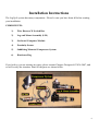
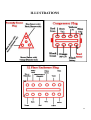
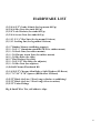
Installation Manual
Generation II Harley
Heritage Softail Models
1996-Present
Copyright 2015, Pete Giarrusso, Inc.
D/B/A Chopper Design Services
All Rights Reserved
2
Table of Contents
INTRODUCTION .................................................................................... 4
WARRANTY ............................................................................................ 5
INSTALLATION INSTRUCTIONS ...................................................... 6
PREPARE FOR INSTALLATION ...................................................................... 7
PREPARE LEFT SADDLEBAG .......................................................................... 8
CONTROL SWITCH BOX ................................................................................... 9
WIRING HARNESS ............................................................................................ 10
LEG & MOUNT ASSEMBLIES ......................................................................... 13
1999 & EARLIER LEG MOUNTING................................................................ 16
RUNNING AIR LINES ........................................................................................ 18
MOUNT PROXIMITY SENSOR ....................................................................... 21
INSTALL THE COMPRESSOR ........................................................................ 22
FINISHING UP ..................................................................................................... 25
FINAL ADJUSTMENTS & MAINTENANCE MODE................................................... 26
MAINTENANCE MODE ................................................................................................ 26
WHEEL ADJUSTMENT ................................................................................................. 27
TEST RIDE ........................................................................................................... 30
GENERATION I UPGRADE INSTRUCTIONS................................. 32
PRE 1996 WIRING ADDENDUM........................................................ 33
ILLUSTRATIONS ................................................................................. 34
HARDWARE LIST ................................................................................ 35
3
INTRODUCTION
This manual covers installation of the Generation II LegUp LandinGear system by Chopper
Design Services. This system should only be installed by a qualified technician, or those with
above average mechanical skills. If you are not SURE that you can perform this installation,
please contact us and we will help you find a qualified shop to assist you.
While the Generation II System holds your bike upright very well, you are STILL responsible
for balancing the bike! The system WILL relieve you of some of the weight of the bike and
help you avoid balance problems as you approach a stop, maneuver at slow speeds, and back
the bike up.
Improper installation will void your warranty, so please be very careful!
Thanks for choosing LegUp!
4
Warranty
Chopper Design Services warrants the LegUp system for a period of one year from date of
purchase. This warranty covers replacement parts and/or manufacturer defects. Incidental
damages or costs are the responsibility of the purchaser.
Defective parts are to be returned to Chopper Design at the address below. Purchaser must
contact Chopper Design to receive a Return Material Authorization, prior to returning defective
parts to Chopper Design.
Abuse, improper installation or use, collisions or accidents, are not covered under this warranty.
Replacement parts for this type of damage are available through Chopper Design.
Users of the LegUp system agree that Chopper Design is NOT responsible for personal injuries
or damage to property arising from the use of the system. While we believe this system to be
safe and reliable, the user is advised that use of LegUp is done so at the users’ own risk. Use of
the system implies agreement to the above statements. If you can’t agree with the above,
Chopper Design and its dealers would be happy to refund your full purchase price, before you
install the LegUp System.
Chopper Design Services
1365 Bennett Dr. #101
Longwood, FL 32750
407-834-5007
[email protected]
5
Installation Instructions
The LegUp® system has many components. Please be sure you have them all before starting
your installation.
COMPONENTS:
1)
Wire Harness W Switch Box
2)
Leg and Mount Assembly (L/R)
3)
On-board Computer Module
4)
Proximity Sensor
5)
Saddlebag Mounted Compressor System
6)
Hardware Bag
If you believe you are missing any parts, please contact Chopper Design at 407-834-5007, and
we will rectify the situation. Some of the parts are shown below.
6
PREPARE FOR INSTALLATION
IMPORTANT! Harley Softails® must be at STOCK height in order to install LegUp. This
system is designed to fit Heritage Softail models only! While accommodations for other
Softail models may be able to be made, we can only guaranty fitment to the ‘STOCK’
Heritage models. Contact Chopper Design for help with fitment on anything but the above
model in a completely ‘STOCK’ condition..
IF YOU ARE UPGRADING FROM A GENERATION I SYSTEM, PLEASE READ THE
ADDENDUM TOWARD THE END OF THIS MANUAL ON THIS SUBJECT FIRST!
We suggest that you read this ENTIRE manual before starting this installation. It will save you
time and frustration!
Place the motorcycle on an acceptable bike lift. You will need to keep the bike on its wheels
for most of the installation, and jack the rear wheel off the lift for some portion of the
installation. Make SURE the motorcycle is secure on the lift!
Remove both saddlebags; one we will be modifying slightly and installation of the legs is
MUCH easier with the saddlebags out of the way!
This manual is available at http://landingear.com/pdf/g2installmanuST.pdf . It may be easier to
see some of the pictures in color there.
Let’s begin!
7
PREPARE LEFT SADDLEBAG
One of the first things we want to do is to drill a small hole in the left saddlebag to allow the air
lines to enter the bag.
Make note of the area we are showing you in the picture below. The arrow points to a recess on
the back of the bag.
We want to drill a single 5/16” hole here. The back of the bag is very soft plastic so no pilot
hole is needed. There are two things to watch for here. Make sure you have the left bag, and
make sure you drill the hole where we show you.
We are going to run 2 small airlines through this hole. It is high enough and hidden enough that
it should not allow any water infiltration. If you are still concerned, once we reinstall the
saddlebag, you can use silicone to seal this hole.
Exact placement of the hole is not terribly critical. Once complete it should look like the bag
below.
The next step is mounting the Control Switch Box.
8
CONTROL SWITCH BOX
NOTE: ON pre 1996 models, you will need a bracket to mount the switch housing,
which we should have supplied. In this case, remove the bolts that secure the clutch
perch clamp on the left side, install the supplied bolts through the bracket that has the
box mounted to it, through the supplied spacers, and into the clutch perch (Blue
Loctite here). Once tightened, follow the rest of these instructions.
If your bike requires no bracket as mentioned above, remove the
bolt on the top of the left switch housing on the handlebar. Find
the long thin bolt, thread it through the Control Switch Box,
insert the spacer on the bolt (with a drop of Blue Loctite), and
thread the bolt into the switch housing. Square the box before
tightening the bolt (you may have to re-align the mirror for
clearance).
Route the wire inside the clutch lever and down the bar. Use
wire ties to hold the wire to the bar. Run the wire through the
top triple tree if you can to control it. The idea here is to get the
wires neatly to the front of the tank and routed under the tank.
(It may be easier to remove the plug end and tape the silver plug ends together for this). We
have some pictures below to give you an idea of what this looks like.
On some bikes it is easier to loosen or remove some of the tank mounting bolts. Make sure the
wires do not interfere with anything under the tank, and that there is nothing that would scuff
the wires. Once the wires are under the seat area, you can assemble the plug, if disassembled,
according to the diagram above.
9
WIRING HARNESS
NOTE: If you are upgrading your existing Generation 1 system, please read the
addendum on this upgrade at the end of this manual, before continuing with the
wiring harness.
The harness and the plugs are routed
mostly under the seat. Different models
have different amounts of space in this
area, and all the wires are long enough to
allow you to place the connectors in the
best place for your bike. What you need
to do is get the eight pin plug and the
double white plug from the harness to the
area under the seat. The large 12 place
plug and the connected 8-Pin plug attach
to the Computer and Compressor
respectively, and they need to land near
the left saddlebag. Push the 12-pin/8-pin
wire through the hole shown here between the fender support and the rear fender. We are going
to tie this wire up under the fender support, so pull most all of the slack toward the back of the
bike, until you have 16” of wire past the end of the fender support as shown below.
10
Find the proximity sensor and its three pin plug. Run the wire (plug first) through the same spot
you ran the 2 plugs through, but from the fender into the area under the seat, so you can plug the
3-pin plug into its mate under the seat. Leave the sensor and its mount dangling for now; it will
be mounted later.
We need to find the fuse holder and the black wire with the hoop ends on the harness and get
them to the battery. These two wires run direct power to the compressor when it needs it. This
wire should already be under the seat area. We want to connect the wire with the fuse holder to
the positive terminal of the battery (the battery cable should attach closest to the battery with
this connector and any others attached after
the battery cable, as shown here). Plan
where you want the fuse holder so you can
get to it if it is ever required!
Don’t connect the black wire to the negative
post yet! We will when we are ready to test
the system. Depending on the year of your
bike, it may look very different than the
picture here (this is with everything already
buttoned up!).
Let’s plug some things together!
Disconnect the black fender plug under the seat, and plug the double white plug in-between the
plugs from the bike. If you have trouble finding the fender plug, look for the wires coming
from the back fender; you should follow that to a black plastic plug that is the same size as the
double white plug from the harness. Connect the Control Switch Box plug to its mating
connector under the seat, and plug the proximity sensor plug (3 pin) to its matching connector.
If everything went according to plan, you should have all plug connectors under the seat
plugged to their matching plus, the positive
battery lead (with fuse holder) should be
connected to the positive battery terminal,
there should be a hoop connector near the
negative battery terminal, and on the left
side you should have two big plugs waiting
for a home, and the proximity bracket and
sensor, with no place to go quite yet!
11
Next, we need to secure the wires that go into the saddlebag to the left fender rail, and leave
enough wire for the plugs to reach the computer and the compressor. What we want to do here
is take two wire ties and carefully thread them between the fender strut and fender as shown on
previous page.
Run the wire under the chrome fender support
and tie it off to the two fender supports.
Make sure you have 16 inches of wire
sticking out from the end of the saddlebag
rail, and that the wire is tight to the support.
You can now pull the extra wire back into the
under seat area. Later we will be securing air
lines to this wire, so make sure that will be
possible with your choice of how to attach
this wire!
The only wires left dangling should be the 2 big plugs at the back and the proximity sensor and
mount, which we will handle soon.
12
LEG & MOUNT ASSEMBLIES
IMPORTANT! The GEN II LegUp system replaces your rear foot pegs. We will ship your
system with Touring-bike style floorboards installed. Your existing rear pegs/floorboards
MUST be removed!
Now we need to mount the Legs to the bike. First we need to remove your rear pegs. Typically,
these pegs are mounted to the bike by a #50 TORX Bolt (for 2000-Up Bikes), or Allen bolts for
earlier models. If you have a 1999 or earlier bike, please skip ahead to the next section (1999Earlier Leg Mount).
You first must remove the peg from the mount (bolt & nut or stud & clip), then using a long
TORX Bit (Included for certain year models) or
an Allen wrench; remove the bolt and the mount.
Next we are going to mount a stud to make
installing the leg system easier. Find a stud with
2 nuts mounted on the end (left). Insert the stud
into the rear peg mount hole (blue Loctite here)
and thread it in as far as it will go (just snug).
We want to run this in so we can mount a lock
washer and nut on the back of this stud. Once
you start it in by hand, you can use a wrench on
the outer nut to drive it all the way in (below).
Once this is installed, we want to put a lock washer
and a nut on the back of the stud, sticking out behind
the frame casting. To make sure the nut is as tight as
it can be, hold the nut on the outside of the casting
and tighten the
nut you just
installed
(right).
Mounting this properly and making sure it is tight is
critical; take your time here.
Once you have the stud tight, we need to remove the outer nuts for the time being. We do this
by putting one wrench on the outer nut and another on the inner nut as shown on the next page.
13
The outer nut is loosened, while the inner one is
held firmly. Remove the outer nut completely,
and then you can loosen and remove the inner
nut. Once the nuts are removed (set them aside
for now), the stud should look like the picture
below.
Do the same thing on the other side of the bike. Now
we can move on to installing the legs on the studs we
have just installed.
MOUNT The Legs!
Find the appropriate leg for the side of the bike
you are working on, and slide it onto the stud you
just installed. Place a lock washer, then the first
of 2 nuts on the stud, and start tightening this nut.
You will notice that as the leg draws nearer to the
bike, the bottom point of the leg mount needs to
fit up against the frame casting as seen below.
We want to tighten this nut most of the way, but
need to make sure that you can pivot the leg on its mounting stud just slightly.
14
Next we want to loosen (if not done already) the 2 lock bolts on the adjustment slide (Left 2
Arrows); you don’t have to loosen them very
much. The slide just needs to be able to slide a
bit in its slot. Find the adjustment bolt (Right
Arrow) and tighten it until the slide is held
firmly against the frame casting. The purpose
is to keep the entire system from pivoting, so
tug on the leg and make sure it can’t move.
Double check everything is lined up properly,
then tighten the nut on the mounting stud, the
locking nuts on the slide, and the locknut on
the adjustment bolt, in that order. Once you
are sure everything is tight, add the acorn nut
to the mounting stud (some blue Loctite here),
as shown below, and tighten it securely against
the first.
Give it a tug; it should be very stout! The left side
should look like the picture (below left). If so you
can install the other side the same way. The right
side is a bit tighter because of the exhaust. We
suggest a clean rag over the exhaust below where the
leg mounts to avoid scratches, and using a ratchet to
tighten the mount bolts instead of a wrench (right,
below).
15
1999 & EARLIER LEG MOUNTING
Now we need to mount the Legs to the bike. If your bike is a 2000-Up model, please skip this
section! On 1999 and earlier Softail models, the foot pegs are mounted to the bike using a ½”
Allen bolts through the frame and into a threaded peg mount. First we need to remove these
pegs. Using an Allen wrench as shown below,
hold the peg on a slight angle for leverage, and
loosen, the Allen bolt, and remove the pegs
and the bolt.
Please find the Supplied ½-13 hex bolts and
locking nut supplied. Run the bolt through the
lock washer you just removed, the frame
casting from the inside, then through the leg
and start the locking nut onto the bolt (below).
The leg
is fairly
heavy,
so you
may wish to have a helper here!
Next we
need to get
this bolt
tight, but not
completely
tight. Looking at the picture below, use a ¾” socket
(no extension it won’t fit), and a ¾ open end
wrench, Snug the bolt up most of the way.
The picture at right shows how the leg
snuggles into the casting of the bike; this must
find its spot or the leg will be mounted
crooked.
16
Next we want to loosen (if not done already)
the 2 lock bolts on the adjustment slide (Left 2
Arrows); you don’t have to loosen them very
much. The slide just needs to be able to slide a
bit in its slot. Find the adjustment bolt (Right
Arrow) and tighten it until the slide is held
firmly against the frame casting. The purpose is
to keep the entire system from pivoting, so tug
on the leg and make sure it can’t move. Double
check everything is lined up properly, then
tighten the nut on the mounting stud, the
locking nuts on the slide, and the locknut on the
adjustment bolt, in that order. Once you are
sure everything is tight, final tighten the lock
nut that holds the leg to the bike.
Give it a tug; it should be very stout! The left
side should look like the picture (below right).
If so you can install the other side the same
way. The right side is a bit tighter because of
the exhaust. We suggest a clean rag over the
exhaust below where the leg mounts to avoid
scratches.
17
RUNNING AIR LINES
We need to route the air lines from the
cylinders to the area near the left saddlebag.
You should find 2 long air lines of identical
lengths. On the right side of the bike, press one
end into the fitting on the back of the air
cylinder. These press in relatively easy, but a
small tug will make sure the line is seated.
Guide the line under the mount toward the
front of the bike. We need to use 2 wire ties to
hold the line where we need it before it goes into
the battery area. Don’t over tighten the wire
ties. Once in place, manually push the leg down
and allow it to retract a few times making sure
the line stays away from the pipes.
Once you are sure the line is safe and not
binding, we need to guide it in front of the
swingarm, up through the oil tank to the area
behind the battery. As you can see in the picture,
the line has a nice easy bend to it. While working with these lines, we don’t want to take any
chances with them kinking. This line should be run behind the battery to join the left line as it
follows a path with the wire harness toward
the back of the left saddlebag.
We want to attach the left line to the left
cylinder, and tie the wires off to that mount
just like you did on the right side.
(NEXT PAGE)
18
Again run the leg up and down multiple
times to make sure the line does not bind.
No exhaust on this side, but the belt could
eat through the hose in an instant. Once
you are sure the hose is clear, we need to
run it up behind the oil tank and join it
with the other hose and ultimately tie it to
the wire harness we installed on the fender
strut.
In the picture below, you can see that we
used a wire tie just past the fender strut to
hold both air lines. Tying the hoses just at this spot will maintain the curve you see in the top
left picture that will keep the line away from
the belt and the swingarm. Once this tie is in
place, try to see if the hose can reach the belt.
If it can, you must adjust the ties until the
hoses are safe. Whatever you do, it is critical
that the lines can’t get burned or scuffed. A
little extra patience here will relieve tons of
frustration later from holes in the air lines.
Keep in mind these are air lines; tying them
too tightly can restrict the air flow. Below we
have a shot of the lines tied as they should
be. We added 2 more ties and have arrows
where all 3 should be. Take note of the
rearmost point. This should allow a smooth curve into the hole we drilled in the bag.
Check Both Sides before we move on that by
lowering and raising the legs, there is plenty of
slack for the lines. Readjust your wire ties if need
be, but make sure they work properly to avoid
headaches later!
19
INITIAL SYSTEM TEST
For the time being, assuming all the plugs under the seat are plugged in, we need to plug the
computer into the 12-pin plug hanging off the left fender strut. If you did not attach the negative
cable to the battery, this would be the time to do so! Find the compressor and put it somewhere
stable (on the lift is what we do), and plug the 8 pin plug into it. We just want to make sure
everything is working!
Turn your bike to Accessory Mode (counter clockwise). Your speedometer will illuminate, and
if everything is working properly, the compressor should turn on for about 6 seconds to fill the
onboard air tank. The RED LED (ON
The Sensor) Should Not Be Lit. Take a
metal object (screwdriver, wrench,
etc.) and hold it on the flat face of the
sensor (it has a circle embossed in it).
The LED should light up, and go out
when you move the metal away. If not,
check all your connections. (The
mount here is not a Softail Mount!)
Next, press the rightmost pushbutton
on the handlebar switchbox, and hold it
for at least 3 seconds. One or both
LEDs on the switch panel should light
up or blink; we really don’t care which
at this point. If this occurs, you are doing well. If both LEDs are flashing (maintenance mode)
you can skip the next step which is to press both buttons until both LEDs flash.
Next press both buttons again for just an instant! If everything is working, the bottom or yellow
LED on the switch box should flash, and the top LED should be out. The next step requires
some care. If the bike is still on the lift, have a helper hang on to it as you touch the left button
for just a split second. The legs should move down, likely until the wheels hit or just miss the
lift, and they do this VERY quickly! Again be careful as they could lean the bike if one wheel
touches the lift and the other does not. Press and hold the right button and they should move up.
Again; with the bike on the lift, you have to be very careful here!
If all of the above has occurred, great! If the legs are not all the way up, press and hold the right
button until the legs stop, and turn the ignition switch off! The test is now complete. Disconnect
the Compressor and computer and set them aside.
Let’s move on to mounting the Proximity Sensor.
20
MOUNT PROXIMITY SENSOR
This step is crucial!! Understand it before starting. The proximity sensor tells the system
how fast the bike is traveling. The
proximity sensor mounts to the swingarm at the rear pulley. It will mount
5MM from the pulley. You need to
jack up the rear wheel so we can spin it
to test the sensor and its placement.
Make sure the bike is in neutral.
With the bike up as described above,
turn the ignition switch to the accessory
position. The LED on the sensor should
be out. Bolt the proximity bracket to
the rear-most bolt on the belt guard, so
the sensor aligns near the pulley bolts. Adjust the bracket so the main part of the sensor is
aiming at a pulley bolt and is centered on it (you may have to turn the wheel to do this). What
we are looking for is for the LED to go bright and OFF as a pulley bolt passes the sensor. Play
with this by rotating the
wheel back and forth
while holding the bracket
in place. Once you feel
you have the right place,
hold the bracket steady
and slowly rotate the
wheel. Every time a bolt
passes the sensor, the light
should get bright, and turn
off after it passes.
If this is not happening,
you may need to get the
sensor a bit closer to the
bolts (5MM is a very small
distance!). If you have to move the sensor closer, you may have to bend the bracket a bit. No
matter what you need to do, you MUST make sure that as the wheel turns, the light works as
described above! Once you are certain, tighten the bolts and test again! The automatic
retraction of the legs as well as their deployment RELIES on this sensor being placed perfectly!
21
Once satisfied with the mount, route the wire up the swingarm making sure it is clear and safe.
You need to leave a little slack as it joins the other wires under the seat; the swingarm moves
and we need this slack so the wire is not broken as the wheel goes up and down. Now we can
mount the compressor.
22
INSTALL THE COMPRESSOR
Now that the air lines and wire harness are ready, we need to re-mount the left saddlebag and
install the compressor. While mounting the bag, run the two air lines into the hole you drilled
earlier. We like to place the forward mount on the rubber mounting isolator so it is supported,
and tilt the bag to get the lines in as seen here.
Install and tighten the mounting bolts
inside the bag, and install an acorn nut on
the stud from the rubber isolator. Make
sure the bag mounts are tight!
Next we want to attach the air lines to the
compressor. On the compressor should be
two short air lines with fittings on the
ends. You may want a bit of help here to
keep the saddlebag open.
On the compressor should be two short
air lines with connectors on the ends.
Perch the compressor on the top ledge of
the open bag. Notice that the tank goes
toward the bike as you can see below.
Attach the air lines from the bike to the connectors attached to the compressor (red arrows).
These lines simply push into the in-line connectors as they did on the cylinders on the legs.
Once the air lines are attached, plug in
the 8-pin connector to the connector on
the compressor. It only attaches one
way; make sure it is solidly attached. At
this time, make sure you keep the 12-pin
plug above the top of the compressor, so
you won’t have to fish for it once the
compressor is in the bag. You are about
to see how tight a fit this device is in
your saddlebag.
23
Tilting the front of the compressor system up, carefully lower it into the saddlebag, allowing it
to settle into a spot as far back as it can go. The compressor should feel secure where it sits; the
rubber straps around the air tank should keep it from wanting to tip. Assuming you are happy
with its placement, find the
computer and plug it into the 12pin plug you kept above the top
of the compressor while
installing.
Attach the computer to the top
using the supplied Velcro, with
the wire facing rearward.
Pull all extra slack from the
harness into the bag (make sure
the bag closes easily!). You
want all the plugs, extra wire and
air lines pushed toward the back and below the level of the top. Once complete, you should be
looking at something like the picture below. Next we will tidy some things up.
24
FINISHING UP
Now it is time to reinstall everything you took off, and do a final check of everything! Install
the right saddlebag, then reinstall the seat making sure all your wires are routed neatly, tied off
nicely and don’t interfere with the seat installation.
Once all of this is accomplished, we should get the bike on the ground, and with a helper, cycle
the wheels up and down a few times, having your helper make sure the air lines are not being
scuffed or are over tight, and that the wires are out of the way of anything that could damage
them.
Double-check all your bolts for tightness. Now we can dial in the legs, and adjust the wheels if
needed.
LEAKS!
This system uses air, and air loves to leak! The fittings we use are tested for leaks before
shipping, but we have a few simple tests to make sure you have no leaks or just insignificant
ones if any.
Set the wheels down and leave the system on. Put the kickstand down, and turn the bars all the
way left.
If the compressor makes noise more than once every two minutes, you may have a leak at the
lines that connect to the compressor or the tank fittings. Some soapy water will tell you where
(you will need to remove the compressor top to test for these leaks).
Assuming the compressor doesn’t lose enough air to kick on after 2 minutes, you should be
fine.
You can turn the bike off, and wait to see if in 5 minutes the bike is not as stable as it was when
the wheels were first lowered. If it lasts the 5 minutes and is still very stable, you could still
have a leak, but not one that would be a problem on the road!
Leave the bike on its wheels overnight (again kickstand down, bars full left in case the legs lose
a lot of air; the bike will land on its stand). If in the morning, the bike is still stable you have no
leaks.
If there are leaks, the fittings on the air cylinders would be the first for the soapy water check,
with the two small line fittings on the compressor next! If you need help with these, please feel
free to call us at (407) 834-5007.
25
FINAL ADJUSTMENTS & MAINTENANCE MODE
The next two sections are typically NOT needed. We include them to document your system
thoroughly, but MOST people will never need to use either section.
MAINTENANCE MODE
NOTE: Maintenance mode is a procedure that ‘TEACHES’ the computer how
much pressure to use when it lowers the wheels and how much pressure to
release when raising the wheels. We always set this at the factory; ALWAYS!! We
include this procedure in case it is ever needed in the future. Please skip this
section unless you have been instructed to reset the system by Chopper Design.
Turn the ignition to Accessory and start the LegUp System (hold right button for 3 seconds).
The system should be set at the factory for proper pressure, but some wheel adjustment may be
needed. If it has been determined that ‘Maintenance Mode’ is needed, Sit on the bike, and hold
it level. If both lights on the switch box are flashing, the system is in maintenance mode. If not,
PRESS & HOLD both buttons until all lights flash. (Do your best to press both buttons at the
same time so the system doesn’t respond to what it thinks is a request to lower the legs) Once
flashing, hit both buttons for an instant to get the system in the ‘DOWN’ setting mode (lower,
yellow LED flashing). Touch the left button briefly; the wheels should go down immediately.
(This is VERY quick, don’t be startled!) Using very short pushes of the left button, press and
then feel the stability of the bike. If it feels firm enough, try leaning the bike a bit. If the wheels
return the bike to upright, there is likely enough pressure. Put your feet on the floorboards; the
bike should stand on its’ own. Rock the bike a bit left and right, being prepared to put your feet
down. If the bike continues to come back to upright, the DOWN stop is now set and we can
move on.
Hit both buttons for a moment to get into the ‘UP’ stop mode (Usually hitting the left button
just before the right assures that air is not released!) The top LED should now be blinking.
Press and hold the right button to raise the legs. Listen as the air evacuates; once it is quiet, let
go of the right button. The UP stop is now set! Hit both buttons when complete, Both LEDs
should light, and you are done with these adjustment.
Now press the left button and the legs should lower; again this is fast and loud. The bike should
be held up firmly! Hit it again and the legs should retract. If you are satisfied with these limits,
you have successfully installed the LegUp System.
26
WHEEL ADJUSTMENT
The LegUp GEN II system is typically set up at the factory for the height of your bike. The
system is VERY height dependent! If after testing the initial installation, the bike does NOT feel
stable, the wheel system MAY need to be adjusted to the height of your bike. AGAIN, we
normally ask at order time if your bike is at stock height and we set the system up for whatever
height you have furnished us. DO NOT make any changes unless the stability we expect is NOT
present! If you feel you need to adjust the height/length of the wheel holders, please read this
ENTIRE section before starting the process. If you need help, please contact Chopper Design
at 407-834-5007.
If you are happy with how stable the
bike feels, you can skip this section,
and move on to a test ride! If you are
not sure, a good test is to bring the
wheels down, put the kickstand down,
and lean (or try to) the bike on its
kickstand while sitting on the bike. If
you can’t lean it onto the kickstand
without significant effort, you should
not touch it; move on to the next
section (Test Ride), the wheel settings
are fine!
The stability of the GEN II LegUp
system, relies on the pneumatic
actuator, when deployed, being at an angle that is forward of perpendicular for best results!
Different bikes are at different heights, and Chopper Design uses an ingenious method to adjust
the length of the supporting legs to maximize the stability it affords.
Typically, we will send the ‘Leg Assemblies’ set up for the bike you told us you had. We have
three different ‘Standard’ setups for the Harley Touring bikes. Standard FL Height, Street
Glide and other bikes using the Harley lowered shocks, and the new ‘Ultra Low’ models. The
Softail setup is just a bit lower than the standard touring bike.
The first picture (above) shows the setup for standard height Softails. The wheel holder is set
with the strap facing up and the small bolts set in the 3rd and 5th hole from the back of the leg
(Notice curve of wheel holder) with the bolt in the second hole on the wheel holder (wheel
rotates a bit extra toward the back). The axles are set in the higher of the two holes on the
wheel holder. I know this sounds confusing, but it is all part of the fine tuning of the height of
length of the legs. This is how we should have sent the legs to you.
27
This picture at right shows the tools we
have at our disposal to adjust the wheels
if needed. The big bolt (#2) can be
placed in 2 positions, the small bolts (#3
we have 2 of these) can be used to rotate
the wheel holder a bit, and the axle (#1)
can be placed in 2 different positions.
Another option you have which will
shorten the leg length is to remove the
wheel holder (axle and 2 small bolts
out), turn it over and install it on the
other side of the bike. This keeps the
wheels in the correct position, and
avoids you having to remove the wheels
and turn them around as well.
If the bike, with its normal passenger
load is not stable enough with the
wheels down or it drops more than ½”
when transitioning from wheels down to wheels up, you may wish to try some small
adjustments, using the above tools.
Whatever you do, try to keep the wheel holder under the leg when the legs are extended as
much as possible. Rotating the wheel holder too far back lends leverage, and makes the system
much less stable.
As we have said before, the system should be close if not perfect the way we send it to you.
Shock condition and bike loading are the two main reasons you may wish to make these
adjustments. In many cases you can contact us and send us a picture with the wheels down and
rider(s) up, and we can recommend what changes to make, to get the system the BEST it can be
for you. Be patient and call us for help if you are having any trouble.
On the next page we have some pictures to help you understand what we have tried to show and
explain here.
28
Above you can see the wheels reversed from the left picture to the right. Notice the curve is
different. The right one is shorter than the
left (shorter is what bikes that are a bit lower
require!).
At left is a picture that shows the angle of
the actuator when the wheels are set
properly. Notice the bottom of the cylinder
(silver, inside the black legs) is further
forward than the top! Yours should look like
something like this.
If you are still not getting the stability we
describe here, please call us, and we will try
to determine why not (407-834-5007).
29
TEST RIDE
Get the bike to a clear paved mostly level area where you can test ride it. Start the bike, turn on
the LegUp system and lower the legs. The first test should be done in a straight line. Put the
bike in gear and slowly accelerate. You may notice that the bike tends to want to steer a small
amount left or right. This is normal unless it is severe. Effectively, you are driving a trike, and
steering is done with the handlebars NOT by leaning. Once underway, (we recommend you
keep your thumb near the left button, and press it to raise the wheels if there are any surprises)
the top LED should flash at around 6 MPH, meaning the legs are retracting. It is difficult to
lean on one wheel or the other as you leave, so you may wish to raise the wheels manually if the
bike is steering due to uneven pavement.
Assuming the legs are retracted, you should try to deploy the wheels. As you come to a stop,
the Green LED should be on. As you slow down (almost stopped), the Yellow LED should
illuminate at the proper speed. Once it does (sometimes hard to see), hit the left button and put
your feet down near the ground. The top LED should flash and the wheels should deploy
almost instantly underneath you! Make sure you are ready to balance the bike, though you
likely won’t have to! Immediately after the wheels touch the ground, the bike should be
supported reasonably, but the cylinders can take up to 6 seconds to get completely filled. Make
sure you balance the bike as this occurs. The slower you are going when deploying the wheels,
the smoother the transition will be from wheels up to wheels down. Practice these maneuvers
until you are comfortable with the wheel adjustments and the system operation.
SEMI-AUTOMATIC DEPLOYMENT: Another way to deploy the legs is semi-automatically.
First we must be SURE that the proximity sensor is working properly or the wheels could come
down at higher speeds than we wish. If you are travelling at a speed over 10 MPH, AND the
yellow light (bottom) on the handlebar control is out, hit the left button. The bottom or yellow
LED should start to flash. When you slow down to around 5MPH the wheels will deploy (see
the red/green flash on top LED). Again prepare to put your feet down. IF the lower LED is lit at
a speed over 10 MPH, don’t hit that button; see caution below!
NOTE: The bottom LED Should not be LIT SOLID if the bike is travelling over
10MPH! In the event it is, the wheels will deploy instantly if you try to set them as
above; this is dangerous! You MUST re-visit the sections on testing the proximity
sensor. You should always be aware that this light should NOT be on if you are
traveling at speed, and ‘Arming’ the system for deployment should only be
attempted if the lower LED is Not Lit! Please see the User Manual for more
information on Proximity Sensor Failure!
30
The next thing to try is to make a turn from a dead stop with the wheels down. As soon as you
start the bike moving, turns can only be made by using the handlebars. The LegUp system is too
strong to allow a great deal of lean with the wheels down! If you need to make a turn shortly
after departing from a stop, raise the wheels manually (left button) and you will get complete
control again.
The next thing to try is slow speed maneuvering with the wheels lowered. If you keep your
speed down, most slow speed maneuvers can be accomplished with your feet up, keeping in
mind that at about 6 MPH the wheels will come up automatically! You can try full lock turns in
both directions and the bike should stay upright with your feet up.
Understand; it is always a good idea to keep your feet near the ground during these maneuvers
if you can. A mechanical failure or a wheel in a pothole could upset the bike.
Because the wheels are right behind your legs when they are down, we recommend not trying to
push with your feet to move the bike forward. Use the engine and keep your feet out of the way;
this way the legs don’t bite at your heels as the floorboard always have! Backing up using your
feet works fine and the chore of balancing the bike is taken care of for you.
Practice, practice, practice!! Enjoy your LegUp System!
31
GENERATION I UPGRADE INSTRUCTIONS
NOTE: Read this before starting your installation if this is an upgrade!
If you are upgrading from a Generation I system, most all the instructions in this manual pertain
to you, but some do not! The most important thing is to NOT take your wiring harness off the
bike! We should have supplied you with an upgrade harness that will allow you to keep most
everything as it was, and adapt the wiring to the new system. The second VERY important
thing is that your computer MUST be sent in for upgrading or it will not work with the new
Generation II system! With those facts in hand, let’s get to it!
We will assume you have already removed all your Gen I hardware. The legs, the actuator
mounts, the mounting plate. All you should have left from the old system is the wiring harness.
The upgrade harness plugs into where the old computer plugged in. This is a 12 pin plug on the
opposite end of the upgrade harness from the two plugs that are close together.
Once this is plugged in, you should attach the harness with the 12-pin harness to the fender
support as described in the regular instructions, so it can wind up in the saddlebag. Along with
this, attach the thin wire from upgrade harness that has 2 hoop connectors on it to the fender
support and get that wire to the battery. The existing 12-pin plug and most of the upgrade
harness will be tucked in the bag behind the compressor with the extra air line.
These are only suggestions; run the wires anyway you like; your existing connections to power
will remain as they are. One caveat is that the plug that used to run to the actuator will have no
plug in it. This should not be a problem assuming it is stored in an area that does not get very
wet.
When reading the install manual, you should be able to ignore most all instructions having to do
with wiring and you will NOT need to do the proximity test by rolling the bike, as this should
remain mounted.
If you have any trouble with this upgrade, please give us a call at 407-834-5007.
32
PRE 1996 WIRING ADDENDUM
On bikes older than 1996, the plug for the fender wiring cannot be used as it is on other models.
Our wiring harness will have two wires where the white plug would normally be. These two
wires will be orange and black.
The orange wire MUST be hooked up to something that turns on and off with the bike. Usually
a wire that is blue or more preferably orange or orange with a white stripe is safe. We
recommend you find what you wish to use, test it and cut, solder and heat-shrink the wires for
safety.
The black wire can be hooked to any ground; the battery, a screw on the frame, or any black
wire in the harness.
33
ILLUSTRATIONS
34
HARDWARE LIST
(2) 3/8-16 X 2” Grade 8 Studs (for leg mount 00-Up)
(4) 3/8-16 Hex Nuts (for studs 00-Up)
(2) 3/8” Lock Washers (for studs 00-Up)
(2) 3/8-16 Acorn Nuts (for studs 00-Up)
(2) ½-13 X 1 ¾” Hex Nuts (for leg mount 99-down)
(2) ½-13 Locking Nut (for leg mount 99-down)
(2) ¼” Rubber Mounts (saddlebag support)
(2) ¼ - 20 X ½” Aluminum standoffs (M/F for rubber mount)
(2) ¼ - 20 Lock Nuts (for rubber mount)
(2) ¼ - 20 Chrome Acorn Nuts (for rubber mount)
(4) ¼ - 20 Hex Bolts (for slide)
(4) ¼” Flat Washers (for slide)
(2) ¼ - 20 X 1.25” Hex Bolts (for adjuster)
(2) ¼ - 20 Hex Nuts (for adjuster)
(1) Softail Chrome Floorboard Kit
(2) 1/4-20 X 2” Chrome Allen Bolts w Split Washers (95-Down)
(2) ¼” X 7/16” X 7/8” Spacers (HB Bracket 95-Down)
(2) 5/32” Black Air Line, 5 Foot Long (cylinders to saddlebag)`
(2) 5/32” Black Air Line, 2 Foot Long (valves to unions)
(2) 5/32” Union Fittings
Big & Small Wire Ties, self-adhesive clips.
35