1
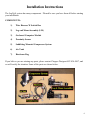
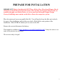
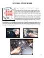
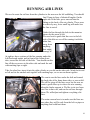
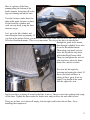
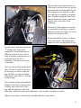
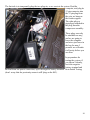
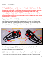
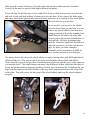
Installation Manual
G2 Harley Switchback
2012-Present
Copyright 2014, Pete Giarrusso, Inc.
D/B/A Chopper Design Services
All Rights Reserved
2
Table of Contents
INTRODUCTION .................................................................................... 4
WARRANTY ............................................................................................ 5
INSTALLATION INSTRUCTIONS ...................................................... 6
PREPARE FOR INSTALLATION .................................................................... 7
MOUNT AIR TANK............................................................................................ 8
CONTROL SWITCH BOX............................................................................... 10
WIRING HARNESS .......................................................................................... 11
LEG & MOUNT ASSEMBLIES ....................................................................... 14
RUNNING AIR LINES ..................................................................................... 16
INSTALL THE COMPRESSOR ...................................................................... 18
MOUNT PROXIMITY SWITCH..................................................................... 22
FINISHING UP .................................................................................................. 25
FINAL ADJUSTMENTS & MAINTENANCE MODE .................................................26
MAINTENANCE MODE ................................................................................................26
WHEEL ADJUSTMENT ................................................................................................27
TEST RIDE ........................................................................................................ 30
ILLUSTRATIONS ................................................................................. 32
SADDLEBAG DRILLING TEMPLATE ............................................. 33
HARDWARE LIST ................................................................................ 34
3
Introduction
This manual covers installation of the Generation II LegUp LandinGear system by Chopper
Design Services. This system should only be installed by a qualified technician, or those with
above average mechanical skills. If you are not SURE that you can perform this installation,
please contact us and we will help you find a qualified shop to assist you.
While the Generation II System holds your bike upright very well, you are STILL responsible
for balancing the bike! The system WILL relieve you of some of the weight of the bike and
help you avoid balance problems as you approach a stop, maneuver at slow speeds, and back
the bike up.
Improper installation will void your warranty, so please be very careful!
Thanks for choosing LegUp!
4
Warranty
Chopper Design Services warrants the LegUp system for a period of one year from date of
purchase. This warranty covers replacement parts and/or manufacturer defects. Incidental
damages or costs are the responsibility of the purchaser.
Defective parts are to be returned to Chopper Design at the address below. Purchaser must
contact Chopper Design to receive a Return Material Authorization, prior to returning defective
parts to Chopper Design.
Abuse, improper installation or use, collisions or accidents, are not covered under this warranty.
Replacement parts for this type of damage are available through Chopper Design.
Users of the LegUp system agree that Chopper Design is NOT responsible for personal injuries
or damage to property arising from the use of the system. While we believe this system to be
safe and reliable, the user is advised that use of LegUp is done so at the users’ own risk. Use of
the system implies agreement to the above statements. If you can’t agree with the above,
Chopper Design and its dealers would be happy to refund your full purchase price, before you
install the LegUp System.
Chopper Design Services
1365 Bennett Dr #101
Longwood, FL 32750
407-834-5007
[email protected]
5
Installation Instructions
The LegUp® system has many components. Pleased be sure you have them all before starting
your installation.
COMPONENTS:
1)
Wire Harness W Switch Box
2)
Leg and Mount Assembly (L/R)
3)
On-board Computer Module
4)
Proximity Sensor
5)
Saddlebag Mounted Compressor System
6)
Air Tank
7)
Hardware Bag
If you believe you are missing any parts, please contact Chopper Design at 407-834-5007, and
we will rectify the situation. Some of the parts are shown below.
6
PREPARE FOR INSTALLATION
IMPORTANT! Harley Switchbacks® MUST have Harley Rear Floorboard Mounts (Part #
49349-07) to install the Generation II System. These mounts (and optional floorboards) are
available through your Harley Dealer, or can be purchased through Chopper Design.
Factory Saddlebags must remain on the bike to house the compressor system.
Place the motorcycle on an acceptable bike lift. You will need to keep the bike on its wheels
for most of the installation, and jack the rear wheel off the lift for some portion of the
installation. Make SURE the motorcycle is secure on the lift!
Remove the seat and disconnect the battery.
This manual is available at http://landingear.com/pdf/g2installdyna.pdf . It may be easier to see
some of the pictures in color there!
We are now ready to begin!
7
MOUNT AIR TANK
One of the first things we
want to do is to mount the
air tank and drill the left
saddlebag for air lines. The
holes we need to drill are
small, and can be filled in if
the system is ever removed.
We start by mounting the
captive air tank and its
included bracket to existing
bolts on the left saddlebag.
Remove this saddlebag and
place it as shown here on a
soft (non-scratching
surface).
The two bolts in this picture (one circled, the other being tightened) get removed, then the
bracket and tank are placed over the bolt holes, and the stock bolts are reinstalled (us a bit of
blue Loctite here). Once these are installed, we can move on to drilling for air lines.
The second to last page of this manual has a
drilling template. You will need to cut this
template out carefully and attach it to the
saddlebag. This will allow you to drill one of
the two holes through an existing hole in the
metal support structure, inside the saddlebag.
As you can see in the photo, the template has
two curves to match the curves on the upper
and lower brackets on the back of the
saddlebag. Attach the template carefully with
tape, then, using a punch; mark just the lower
hole so you can drill it.
The final hole size for these holes will be 5/16”, but the bottom hole needs to be start drilled
with a reasonably small (1/8” or smaller) bit. You will see why in a moment.
8
Once you have drilled the first hole, look inside the bag. The hole should have wound up
coming through the existing hole we talked about earlier. Assuming this is the case, carefully
use a 5/16” bit, and drill the hole
the rest of the way, allowing the
bit to wander its way into the
existing hole. It is no big deal if
the hole winds up outside the hole
in the inner support metal, but
with a little care, you can avoid
this.
Next you can punch and drill (full
size) the upper hole, as this is
though plastic only. Make sure
both holes are smooth, as we will
be running air lines through them
and burs are not desirable here.
Once complete, set the bag aside, rather than reinstalling it on the bike.
9
CONTROL SWITCH BOX
Remove the bolt on the top of the left switch housing on the
handlebar. Find the long chrome bolt, thread it through the
Control Switch Box, insert the spacer on the bolt and (with a
drop of Blue Loctite), thread the bolt into the switch housing.
Square the box before tightening the bolt (you may have to realign the mirror for clearance). Route the wire inside the clutch
lever and down the bar. Use wire ties to hold the wire to the bar.
Run the wire through the top triple tree if you can to control it.
The idea here is to get the wires neatly to the front of the tank
and routed under the tank. (It may be easier to remove the plug
end and tape the silver plug ends together for this). We have
some pictures below to give you an idea of what this looks like.
On some bikes it is easier to loosen or remove some of the tank mounting bolts. Make sure the
wires do not interfere with anything under the tank, and that there is nothing that would scuff
the wires. Once the wires are under the seat area, you can assemble the plug, if disassembled,
according to the diagram above.
10
WIRING HARNESS
The next step is to route the wiring harness. The
harness and the plugs are routed mostly under the seat,
and toward the left saddlebag. Different models have
different amounts of space in this area, and all the
wires are long enough to allow you to place the
connectors in the best place for your bike.
On the Dyna, it is difficult to get wires from the left
saddlebag area, under the seat. We need to move the
left electrical box, away from the bike for a moment to
fit the large plugs through (or you can take apart and
reassemble the plugs, but this is easier!) Remove the
left side cover and find a single Allen bolt in the
middle of the electrical box (left). Remove this bolt
completely and then remove the two top bolts
securing the box, as seen at right.
Once these are removed, we are can wiggle the box
loose and move it out just a bit. You will see there is
a raised plastic piece that needs to come down far
enough to clear the frame and allow us to pull the
box out just a few inches, as seen below.
Find the two BIG plugs on the harness (12
pin with an 8 pin pigtail attached), and
slide them through the seat area, and out
just below the left fender support. Once
both plugs are through, you can pull most
of the slack out.
Find the proximity sensor and its three pin
plug. While the box has made this room for
us, we should push the three pin plug up
under the seat through the same space you
just brought the other plugs down through.
Now you can reinstall the electrical box. With the plugs past the box, the wire can be adjusted
to get any extra length back under the seat later, as we finish up!
11
We need to find the fuse holder and the black wire with the hoop end and get it to the battery.
These two wires run direct power to the compressor when it needs it. We can start this wire
toward the forward right corner of the under seat area, and run it out in front of the battery.
These two connectors get
attached directly to the battery.
For now, attach the wire with the
fuse holder, to the positive (front)
battery terminal, and leave the
black wire loose near the negative
cable (which should be
disconnected already!). We like
to put the fuse holder under the
rubber strap, which keeps the
wires tame.
When you have done this, pull all
the extra slack up into the area
below the seat.
Let’s plug some things together!
Disconnect the black fender plug
under the seat, and plug the
double white plug in-between the
plugs from the bike (don’t worry about the small black appendages; they are not used for
anything). Connect the Control Switch Box plug to its mating connector under the seat, and
plug the proximity sensor plug (3 pin) to its matching connector.
If everything went according to plan, you should have all plug connectors under the seat
plugged to their matching plus, the positive battery lead (with fuse holder) should be connected
to the positive battery terminal, there should be a hoop connector near the negative battery
terminal, and on the left side you should have two big plugs waiting for a home, and the
proximity bracket and sensor, with no place to go quite yet!
Next, we need to secure the wires that go into the saddlebag to the left fender rail, and leave
enough wire for the plugs to reach the computer and the compressor.
12
Start by getting the wire with the 2 big plugs on it, run inside the left shock toward the back of
the bike. Next, measure 8 inches back from the 12 pin (biggest) plug and mark the wire. We are
trying to make sure we have all the wire we need but not too much extra.
Run the wire under the
chrome fender support
and tie it off to the two
fender supports. On
some bikes, you can
actually get the wire
ties between the
fender and the strut,
and secure them
around the bolts, on
others with removable
hardware you may
have to secure it to the
fender support itself,
or the chrome saddlebag mounting points.
No Matter how you need to secure the wire, make sure you have 8 inches of wire sticking out
from the end of the saddlebag rail, and that the wire is tight to the support. You can now pull the
extra wire back into the under seat area. Later we will be securing air lines to this wire, so make
sure that will be possible with your choice of how to attach this wire!
The only wire left dangling should be the proximity sensor and mount, and we will handle that
soon.
13
LEG & MOUNT ASSEMBLIES
IMPORTANT! Harley Switchbacks® MUST have Harley Rear Floorboard Mounts (Part #
49349-07) to install the Generation II System. These mounts (and optional floorboards) are
available through your Harley Dealer, or can be purchased through Chopper Design.
Factory Saddlebags must remain on the bike to house the compressor system.
Now we need to mount the Legs under the passenger floorboards.
Before we start, we recommend that you change the mount bolts
for the floorboard mounts that are required for your installation.
Harley supplies Torx bolts, which are easy to strip and hard to
tighten.
We like to use hex bolts here so you can check how tight they are
on a regular
basis, more
easily. We have supplied the bolts and lock
washers, so remove one bolt at a time on each
mount, then using some blue Loctite on each,
replace the Torx bolts with the hex bolts and
lock washers. These bolts need to be checked
often for tightness as the floorboard mounts
support our wheels and take a bunch of abuse!
Next we want to mount each of the assemblies,
and we start by putting some blue Loctite on
the supplied chrome Allen bolts, putting the
bolts into the top mount, and laying the
mount on the floorboard mount as seen here.
Once the top mount is in place, we can
mount one of the legs.
The Leg/Mount system is heavy so you may
want to get a helper here. Ben has done this
so many times he does it by himself, but you
will likely appreciate an extra hand.
The mount has cutouts that fit tightly to the
underside of the floorboard mount. Find the
mount for the side of the bike you are on,
and offer it up to the floorboard mount,
feeling the obvious spot it fits into. Start
14
tightening the Allen bolts a little on each side. Shortly the majority of the weight will be held by
the bolts. You need to get this very tight, but must alternate so the mount stays even.
When you are done, you
should have the smallest
gap on each side of the
top mount, and they
should be about the
same.
It is imperative that you
make sure the mount is
in the right place and
that it is tight! Here you
can see the bottom of the
floorboard mount, and
how it is even, and snug
against the mount.
Give it a tug; it should
be very stout! If it is,
install the other side in the same fashion, and we can move onto running the air lines!
15
RUNNING AIR LINES
We need to route the air lines from the cylinders to the area near the left saddlebag. You should
find 2 long air lines of identical lengths. On the
right side of the bike, press one end into the
fitting on the back of the air cylinder. These press
in relatively easy, but a small tug will make sure
the line is seated.
Guide the line through the hole in the mount as
shown by the arrow at left.
We now need to guide that line over to the left
side of the bike as we will be running it with the
other line,
away from
anything
that might
damage it!
At right we have a picture of the line running under the
left floorboard mount, and in front of the frame down
tube, toward the left side of the bike. You should run this
line all the way across to the other side and mark the end
with masking tape as right.
Take the other line; insert it into the right cylinder as you did on the other side. Mark the far end
as left and tie the marked ends together with masking tape, so we can run them together.
We want to run the lines under the belt and toward
the back side of the frame down tube, as seen at left.
We will be tying off the lines soon, but for now we
want to guide these up to where the wire running
along the fender support is. We like to tie two loose
wire ties to that wire, and run the air lines through
them. We will adjust and tighten everything a bit
later.
The main concern here is to make sure the lines are
run where they will be safe from the belt or pipes or
anything that could hurt them.
16
Here is a picture of the lines
running along the bottom of the
fender support, being tied off to the
big wire running toward the back.
You don’t want to make those ties
tight at this point, because we have
to start from the cylinders and
work our way back, tying the lines
down as we go.
Let’s go to the left cylinder, and
start setting the lines up properly. If
you look at the picture below, you will notice how some slack was left in the line and it was tied
off to the floorboard mount. This is very important. The way we do this is to run the line
through the guide in the mount,
then through a slightly loose wire
tie on the floorboard mount.
Then using your hand, you can
lower the leg all the way down,
which should pull some slack.
Then you can tighten the wire tie
a bit, and move on to the frame
down tube, and tie it to that.
Now test the line again by
lowering and raising the wheel. If
there is no bind, and there is
plenty of slack, great, if not try
again! You should do the same
with the right side, next.
Just be sure there is plenty of room for the lines to move. Then you can start working back tying
off the lines. Tighten the lines under the fender strut, and just leave the end wild for now!
These are air lines, so tie them off snugly, but too tight could restrict the air flow. On to
installing the compressor!
17
INSTALL THE COMPRESSOR
Now we are going to get the compressor installed in the saddlebag and get the air lines and plugs attached to
it. The picture shows the compressor and its top, the way it should have been shipped to you.
First we need to remove the top, as it won’t be needed until
the very end! We do this by removing the three nylon nuts
on the top of the plate. These are only hand tight and will
be put back on without any tools as well.
Once the top is off the compressor should look like the
picture below. Now we have to prepare the saddlebag and
mount it back on the bike.
First we need to attach the ¼” fat tubing to the
air tank, and push the extra hose into the bag
via the bottom hole. We also need to take two
small lines and pushed them in to the top hole
we drilled into the bag.
Now we can re-install the saddlebag.
Once it is on, pull the extra slack of the hose
into the bag. Next we install the compressor.
18
Take the three lines and put them out
of the way as we have here; we tucked
them under the cloth that holds the lid.
The compressor is a tight fit, so slide
it in with the two standoffs toward the
front. Usually keeping the back lower
than the front is the easiest, and work
it all the way to the back of the
saddlebag.
The bottom of the compressor mount
is contoured to fit the bag, so when it
finds the spot that it is happy in, it will
stay there on its rubber feet.
We next attach the air lines, as shown
in the next picture. The big line gets
trimmed (a razor or sharp knife is best
for clean cuts), and inserted into the
‘T’ fitting at the front of the
compressor. Your fittings may be
different in color. Leave a bit of
slack in the line, but make sure it is
under the top of the silver
standoffs, so the top cover can be
re-installed.
Next we want to hook up the small
lines. We like to make a loop and
tie it loosely so when we take the
bag off, there is some extra slack.
Keep track of which line is left and
which is right.
We just make a loop and install the
left line in the front connector that
is all the way in the back of the
bag, and the right one in the back
connector. Again the connections should get a tug, to make sure they are seated.
When you are done, it should look something like the picture above.
19
The last task is to temporarily plug the two plugs in, so we can test the system. Find the
computer, and plug its
12 pin connector into
the 12 pin plug from
the wire we hung on
the fender support.
The other plug or
pigtail gets attached to
the plug from the
compressor assembly.
These plugs can only
be attached one way,
and we are going to
leave the computer
and wires just loose in
the bag for now. I
promise we will make
it all pretty before you
are done.
In preparation for
testing the system, if
you haven’t already,
hook the negative
battery terminal and
the lead from our power connection, up to the negative battery terminal. On to Initial Testing
(don’t worry that the proximity sensor is still lying on the lift!).
20
INITIAL SYSTEM TEST
Turn your bike to Accessory Mode (counter clockwise). Your speedometer will illuminate, and
if everything is working properly, the compressor should turn on for about 6 seconds to fill the
onboard air tank. At this point, have a look at the yellow proximity sensor. The RED LED
(ON The Sensor) Should Not Be Lit. Take a metal object (screwdriver, wrench, etc.) and hold it
on the flat face of the sensor (it has a
circle embossed in it). The LED should
light up, and go out when you move
the metal away. If not, check all your
connections.
Next, press the rightmost pushbutton
on the handlebar switchbox, and hold it
for at least 3 seconds. One or both
LEDs on the switch panel should light
up or blink; we really don’t care which
at this point. If this occurs, you are
doing well. If both LEDs are flashing
(maintenance mode) you can skip the
next step which is to press both buttons
until both LEDs flash.
Next press both buttons again for just an instant! If everything is working, the bottom or yellow
LED on the switch box should flash, and the top LED should be out. The next step requires
some care. If the bike is still on the lift, have a helper hang onto it as you touch the left button
for just a split second. The legs should move down, likely until the wheels hit or miss the lift,
and they do this VERY quickly! Again be careful as they could lean the bike if one wheel
touches the lift and the other does not. Press and hold the right button and they should move up.
Again; with the bike on the lift, you have to be very careful here!
If all of the above has occurred, great! If the legs are not all the way up, press and hold the right
button until it stops, and turn the ignition switch off!
The test is now complete. Let’s move on to mounting the Proximity Sensor.
21
MOUNT PROXIMITY SWITCH
This step is crucial!! Understand it before starting. The proximity sensor tells the system
how fast the bike is traveling. The proximity sensor mounts to the swing-arm at the rear pulley a
mere 5MM from the pulley bolts. You need to jack up the bike so we can spin the rear wheel
and test the sensor and its placement. Make sure the bike is in neutral.
With the bike up as described above, turn the ignition switch to the accessory position. The
LED on the sensor should be out. Slide the proximity bracket onto the swing-arm so the sensor
aligns near the pulley bolts (DO NOT ATTACH IT WITH TAPE AT THIS TIME). Adjust the
bracket so the main part of the sensor is
aiming at a pulley bolt and is centered on it
(you may have to turn the wheel to do this).
What we are looking for is for the LED to go
bright and OFF as a pulley bolt passes the
sensor. Play with this by rotating the wheel
back and forth while holding the bracket in
place. Once you feel you have the right place,
hold the bracket steady and slowly rotate the
wheel. Every time a bolt passes, the light
should get bright when the bolt is nearby and
off after it passes.
If this is not happening, you may need to
get the sensor a bit closer to the bolts
(5MM is a very small distance!). If you
have to move the sensor closer, you may
have to bend the bracket a bit. No matter
what you need to do, you MUST make
sure that as the wheel turns, the light
works as described above! Once you are
certain, attach the bracket with the
supplied 2-face tape, and test again! The
automatic retraction of the legs as well as
their deployment RELIES on this sensor
being placed perfectly!
Once satisfied with the mount, skip down to the wire routing instructions below.
22
WIRE ROUTING
The Proximity sensor wire will run down the swing
arm to the same frame down tube that you tied the
air lines off to. Use the supplied self-adhesive tabs,
to secure the wire snugly to the swing arm. Then
leave a bit of slack and tie the wire to the down tube,
and do what you need to do to secure the wire safely,
and finally pull all the extra wire under the seat area.
Your wire from the handlebar should already be
under the seat, tied off to the handlebar
neatly from the switch to the triple tree,
and secured safely under the tank. Now is
a good time to tie up all the wires under
the seat. First make sure you have all
excess slack pulled under the seat. There is
not a ton of room here on the Dyna, so we
loop our wires, tie the excess as a bundle,
make sure they don’t interfere with the
seat, and tuck them in as shown here.
We already have the two plugs in the left
saddlebag, now we need to cut a small notch in the top of the bag to avoid hurting the wire as
the bag is opened and closed. This small notch will NOT compromise the weatherproof nature
of the saddlebag.
Make a mark near the back of the bag on the
inside lip, as you see here. We use a rotary bur,
but you can use a file or even a keyhole saw.
Cut a notch that is about 1/4 - 3/8” wide and
just about the same deep. Make sure the big
wire that connects to the compressor and the
computer fits into the notch without rising
above the top of the edge of the bag (see
below).
23
You may see the white, self-adhesive
clip, just below the notch here. We use
that to guide the wire down the side of
the bag so it lines up with the cutout in
the top! Don’t install this until you
know where the top will line up
(usually directly above the lines
coming through the bag)! Now we
will install the top and clean things up!
We need to make sure the compressor
plug is attached and tucked in as we
install the top. Find the L-shaped metal top that you removed from the compressor earlier. The
top mounts with the curved cutout toward the fender. It is a tight fit, so slanting it into the bag is
best.
As you work the top over the 3 aluminum standoffs, make sure the computer and plug
(sometimes it is easier to unplug the computer until the top is set) are coming through the
curved cutout, as the plug and computer sit on top of the compressor system. Once the top is
fitted, find the 3 nylon nuts and
screw them on the three posts to
secure the cover. These are plastic
nuts so no wrench is required here.
When complete, you want to
Velcro the computer onto the top
and make sure the plug (the
compressor plug stays UNDER
the top) and wires look something
like this. Our main concern here is
to give you as much of the
saddlebag as possible, and make
sure the wires and components are
not going to be chaffed or
damaged.
24
FINISHING UP
Now it is time to reinstall everything you took off, and do final checking of everything!
Reinstall the seat making sure all your wires are routed neatly, tied off nicely and don’t interfere
with the seat installation.
Once all of this is accomplished, we should get the bike on the ground, and with a helper, cycle
the wheels up and down a few times, having your helper make sure the air lines are not being
scuffed or are over tight, and that the wires are out of the way of anything that could damage
them.
Double-check all your bolts for tightness. Now we can dial in the legs, and adjust the wheels if
needed.
LEAKS!
This system uses air, and air loves to leak! The fittings we use are tested for leaks before
shipping, but we have a few simple tests to make sure you have no leaks or just insignificant
ones if any.
Set the wheels down and leave the system on. Put the kickstand down, and turn the bars all the
way left.
If the compressor makes noise more than once every two minutes, you may have a leak at the
lines that connect to the compressor or the tank fittings. Some soapy water will tell you where
(you will need to remove the compressor top to test for these leaks).
Assuming the compressor doesn’t lose enough air to kick on after 2 minutes, you should be
fine.
You can turn the bike off, and wait to see if in 5 minutes the bike is not as stable as it was when
the wheels were first lowered. If it lasts the 5 minutes and is still very stable, you could still
have a leak, but not one that would be a problem on the road!
Leave the bike on its wheels overnight (again kickstand down, bars full left in case the legs lose
a lot of air; the bike will land on its stand). If in the morning, the bike is still stable you have no
leaks.
If there are leaks, the fittings on the air cylinders would be the first for the soapy water check,
with the two small line fittings on the compressor next! If you need help with these, please feel
free to call us at (407) 834-5007.
25
FINAL ADJUSTMENTS & MAINTENANCE MODE
The next two sections are typically NOT needed. We include them to document your system
thoroughly, but MOST people will never need to use either section.
MAINTENANCE MODE
NOTE: Maintenance mode is a procedure that ‘TEACHES’ the computer how
much pressure to use when it lowers the wheels and how much pressure to
release when raising the wheels. We always set this at the factory; ALWAYS!! We
include this procedure in case it is ever needed in the future. Please skip this
section unless you have been instructed to reset the system by Chopper Design.
Turn the ignition to Accessory and start the LegUp System (hold right button for 3 seconds).
The system should be set at the factory for proper pressure, but some wheel adjustment may be
needed. If it has been determined that ‘Maintenance Mode’ is needed, Sit on the bike, and hold
it level. If both lights on the switch box are flashing, the system is in maintenance mode. If not,
PRESS & HOLD both buttons until all lights flash. (Do your best to press both buttons at the
same time so the system doesn’t respond to what it thinks is a request to lower the legs) Once
flashing, hit both buttons for an instant to get the system in the ‘DOWN’ setting mode (lower,
yellow LED flashing). Touch the left button briefly; the wheels should go down immediately.
(This is VERY quick, don’t be startled!) Using very short pushes of the left button, press and
then feel the stability of the bike. If it feels firm enough, try leaning the bike a bit. If the wheels
return the bike to upright, there is likely enough pressure. Put your feet on the floorboards; the
bike should stand on its’ own. Rock the bike a bit left and right, being prepared to put your feet
down. If the bike continues to come back to upright, the DOWN stop is now set and we can
move on.
Hit both buttons for a moment to get into the ‘UP’ stop mode (Usually hitting the left button
just before the right assures that air is not released!) The top LED should now be blinking.
Press and hold the right button to raise the legs. Listen as the air evacuates; once it is quiet, let
go of the right button. The UP stop is now set! Hit both buttons when complete, Both LEDs
should light, and you are done with these adjustment.
Now press the left button and the legs should lower; again this is fast and loud. The bike should
be held up firmly! Hit it again and the legs should retract. If you are satisfied with these limits,
you have successfully installed the LegUp System.
26
WHEEL ADJUSTMENT
The LegUp GEN II system is typically set up at the factory for the height of your bike. The
system is VERY height dependent! If after testing the initial installation, the bike does NOT
feel stable, the wheel system MAY need to be adjusted to the height of your bike. AGAIN, we
normally ask at order time if your bike is at stock height and we set the system up for
whatever height you have furnished us. DO NOT make any changes unless the stability we
expect is NOT present! If you feel you need to adjust the height/length of the wheel holders,
please read this ENTIRE section before starting the process. If you need help, please contact
Chopper Design at 407-834-5007.
If you are happy with how stable the bike feels, you can skip this section, and move on to a test
ride! If you are not sure, or you skipped ‘maintenance mode’ as instructed, a good test is to
bring the wheels down, put the kickstand down, and lean (or try to) the bike on its kickstand
while sitting on the bike. If the bike comes back to center without your help, or you put your
feet on the boards and can bring the bike up by just leaning to the right; move on to the next
section (Test Ride), the wheel settings are fine.
On each supporting leg, you will find two bolts down near the end by the wheels. The two bolts
control the angle of the ‘Wheel Holders’. By moving the wheel forward or back, we can tailor
the length of the support arms to a particular bike.
A helper is handy here. Make sure the wheels are up. Make note of exactly which two holes the
bolts are in. Loosen the locking nuts from the back and remove the bolts; you will notice the
‘Wheel Holder’ can pivot on the big axle bolt. Starting on the left side of the bike, move the
27
bolts one hole counter-clockwise. Go to the right side and move them one hole clockwise.
Loosely fit the nuts (no need to final tighten them at this point).
Lower the legs. Is the bike more or less stable? If it is more stable, and you can sit on the bike
and rock it back and forth without it leaning over you are done. If not, remove the bolts again,
and move them in the opposite direction two holes, and retest. If everything is fine, final tighten
the lock nuts and you are done.
If you need to, you can move the wheels
from the lowest hole, up one hole. You can
remove the wheel holders, turn them over
(strap up instead of down for example) and
install them on the other side of the bike.
You can move the big axle from the low to
the high hole. All these techniques take
patience, but allow significant flexibility to
tailor the system to your bike. On the next
page we show you some examples.
Normally you do not need to do ANY of
these adjustments, but if you need to, we wanted to teach you the methods at your disposal.
The picture below left, shows the wheel holders set up for touring bikes with full length shocks
(Electra Glides etc.) The one at right is set up for lowered bikes (Street Glide and others).
Notice how the curve of the left one is toward the front of the leg, and the curve on the right one
is toward the back? This small change can make a big difference in how stable the bike may be.
If you are having trouble getting the stability you need, you can remove the 2 small and the one
large bolt that connects the wheel holders to the legs, and swap them from one side of the bike
to the other. This will reverse the direction of the wheel holders and keep the wheels aligned
properly.
28
Again, this is only needed if you are not getting the stability we describe above.
Below is a picture that shows the angle of the actuator when the wheels are set properly. Notice
the bottom of the cylinder (silver, inside the black legs) is further forward than the top! Yours
should look like something like this.
If you are still not
getting the stability
we describe here,
please call us, and we
will try to determine
why not (407-8345007).
29
TEST RIDE
Get the bike to a clear paved mostly level area where you can test ride it. Start the bike, turn on
the LegUp system and lower the legs. The first test should be done in a straight line. Put the
bike in gear and slowly accelerate. You may notice that the bike tends to want to steer a small
amount left or right. This is normal unless it is severe. Effectively, you are driving a trike, and
steering is done with the handlebars NOT by leaning. Once underway, (we recommend you
keep your thumb near the left button, and press it to raise the wheels if there are any surprises)
the top LED should flash at around 6 MPH, meaning the legs are retracting. It is difficult to
lean on one wheel or the other as you leave, so you may wish to raise the wheels manually if the
bike is steering due to uneven pavement.
Assuming the legs are retracted, you should try to deploy the wheels. As you come to a stop,
the Green LED should be on. As you slow down (almost stopped), the Yellow LED should
illuminate at the proper speed. Once it does (sometimes hard to see), hit the left button and put
your feet down near the ground. The top LED should flash and the wheels should deploy
almost instantly underneath you! Make sure you are ready to balance the bike, though you
likely won’t have to! Immediately after the wheels touch the ground, the bike should be
supported reasonably, but the cylinders can take up to 6 seconds to get completely filled. Make
sure you balance the bike as this occurs. The slower you are going when deploying the wheels,
the smoother the transition will be from wheels up to wheels down. Practice these maneuvers
until you are comfortable with the wheel adjustments and the system operation.
SEMI-AUTOMATIC DEPLOYMENT: Another way to deploy the legs is semi-automatically.
First we must be SURE that the proximity sensor is working properly or the wheels could come
down at higher speeds than we wish. If you are travelling at a speed over 10 MPH, AND the
yellow light (bottom) on the handlebar control is out, hit the left button. The bottom or yellow
LED should start to flash. When you slow down to around 5MPH the wheels will deploy (see
the red/green flash on top LED). Again prepare to put your feet down. IF the lower LED is lit at
a speed over 10 MPH, don’t hit that button; see caution below!
NOTE: The bottom LED Should not be LIT SOLID if the bike is travelling over
10MPH! In the event it is, the wheels will deploy instantly if you try to set them as
above; this is dangerous! You MUST re-visit the sections on testing the proximity
sensor. You should always be aware that this light should NOT be on if you are
traveling at speed, and ‘Arming’ the system for deployment should only be
attempted if the lower LED is Not Lit! Please see the User Manual for more
information on Proximity Sensor Failure!
30
The next thing to try is to make a turn from a dead stop with the wheels down. As soon as you
start the bike moving, turns can only be made by using the handlebars. The LegUp system is too
strong to allow a great deal of lean with the wheels down! If you need to make a turn shortly
after departing from a stop, raise the wheels manually (left button) and you will get complete
control again.
The next thing to try is slow speed maneuvering with the wheels lowered. If you keep your
speed down, most slow speed maneuvers can be accomplished with your feet up, keeping in
mind that at about 6 MPH the wheels will come up automatically! You can try full lock turns in
both directions and the bike should stay upright with your feet up.
Because the wheels are right behind your legs when they are down, we recommend not trying to
push with your feet to move the bike forward. Use the engine and keep your feet out of the way;
this way the legs don’t bite at your heels as the floorboard always have! Backing up using your
feet works fine and the chore of balancing the bike is taken care of for you.
Practice, practice, practice!! Enjoy your LegUp System!
31
ILLUSTRATIONS
32
SADDLEBAG DRILLING TEMPLATE
Print and Cut out Make Sure Dimension is Correct!
Some printers don’t print to scale!!
33
HARDWARE LIST
(4) 3/8-16 X 1.25” Cad Hex Bolts w/split washers (Floorboard Mounting Bolts)
(4) 3/8-16 X 1.5” Chrome Allen Bolts (Leg Attachment Bolts)
(2) 5/32” Black Air Line, 7 foot long
(2) 5/32” Black Air Line, 1 foot long (Valve to Unions)
(2) 5/32” Union Connectors
(1) ¼” Air Line, 2 Foot Long
Wire Ties, self-adhesive clips.
34