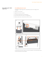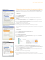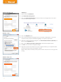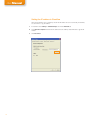
1
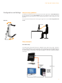
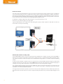
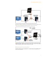
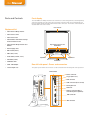
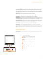
User Manual
Tobii® Technology
Tobii T60 & T120
Eye Tracker
Revision 4
www.tobii.com
User Manual
On Safety
Read this manual carefully before connecting and using
the eye tracker
The Tobii T60 and T120 Eye Trackers are intended only for use in office and home environments.
Do not open the eye tracker!
Non-compliance will result in loss of Warranty! There are no user serviceable components inside and the
risk of electric shock is high due to the presence of Dangerous High Voltages. Contact Tobii support if
your eye tracker is not working properly.
Safety of NIR illumination from the Tobii T Series Eye Trackers
The illuminators of the Tobii T Series Eye Trackers have been tested at ETL SEMKO, Stockholm,
according to IEC/EN 60825-1/A1-A2. The test has shown that the products comply with the standard
for IEC/EN 60825-1/A1-A2 class 1 LED products intended to be used for long time exposure.
The standard IEC/EN 60825-1/A1-A2 states an Accessible Emission Limit (AEL) for continuous long
time exposure. This limit is the maximum illumination that a person should be exposed to for eight hours
a day many days in a row.
The products are intended to be used by a subject at a distance of approximately 60 cm from the eye
tracker. At the regular user distance the exposure, averaged over time, of light from the Tobii T60 and
T120 Eye Trackers to the subject sitting in front of it is 0.1 % of the allowed limit for long time exposure
according to IEC/EN 60825-1/A1-A2 class 1 LED products.
Epilepsy warning
Some people with Photosensitive Epilepsy are susceptible to epileptic seizures or loss of consciousness
when exposed to certain flashing lights or light patterns in everyday life. This may happen even if the
person has no medical history of epilepsy or has never had any epileptic seizures.
Such people may have a seizure while watching certain images or patterns on a monitor, or even when
exposed to the light sources of an eye tracker. It is estimated that about 3-5% of people with epilepsy
have this type of photosensitive epilepsy.
Declaration of Conformity
This equipment has been tested and found to comply with the limits for a Class B digital device, pursuant to part 15 of the FCC Rules and EMC directive 2004/108/EG. The product also conforms with the
directive 73/23/EEC for low voltage and environmental directives 2002/95/EC and 2002/96/ EC.
Note: This equipment has been tested and found to comply with the limits for a Class B digital device,
pursuant to part 15 of the FCC Rules. These limits are designed to provide reasonable protection
against harmful interference in a residential installation. This equipment generates, uses and can radiate radio frequency energy and, if not installed and used in accordance with the instructions, may cause
harmful interference to radio communications. However, there is no guarantee that interference will not
occur in a particular installation. If this equipment does cause harmful interference to radio or television
reception, which can be determined by turning the equipment off and on, the user is encouraged to try
to correct the interference by one or more of the following measures:
* Reorient or relocate the receiving antenna.
* Increase the separation between the equipment and receiver.
* Connect the equipment into an outlet on a circuit different from that to which the receiver
is connected.
* Consult the dealer or an experienced radio/TV technician for help.
All Tobii Eye Trackers are CE-marked, indicating conformity with the essential health and
safety requirements set out in European Directives.
2
Tobii T60 and T120 Eye Tracker
Table of Contents
•
•
•
Quick Start ........................................................................................................................4
First time usage ............................................................................................................................................4
Components checklist ............................................................................................................................4
•
Product Care ..................................................................................................................5
•
Assembling the Tobii T60/T120 ....................................................................... 7
•
•
•
•
•
•
•
•
•
Connecting Tobii Eye Tracker .............................................................................. 8
Setting up the connection to your computer .....................................................................8
Installing the USB Ethernet Adapter ........................................................................................8
Installing the USB User Camera Driver.......................................................................................8
Installing eye tracker software.............................................................................................................8
Setting up the network connection to the eye tracker in Windows ................ 9
Connecting to the eye tracker in Tobii Studio.....................................................................11
Connecting to the eye tracker in ClearView or Tobii SDK.......................................11
Setting the IP address in ClearView............................................................................................12
•
•
•
•
Configuration and settings......................................................................................13
General setup guidelines.......................................................................................................................13
Setup examples..............................................................................................................................................13
Minimum system recommendations............................................................................................15
•
•
•
•
Parts and Controls........................................................................................................16
Front display.......................................................................................................................................................16
Rear left side panel - power and connectors......................................................................16
Screen settings buttons..........................................................................................................................17
•
Customizing the Eye Tracker’s Display............................................................18
•
•
Appendix I: Eye Tracker Upgrade........................................................................21
Eye tracker software upgrade...........................................................................................................21
•
•
•
Appendix II: Troubleshooting Guide..................................................................22
Problems with the Apple Bonjour Service..............................................................................22
Problems with the peer-to-peer network configuration.............................................23
•
•
•
•
Appendix III: Technical Specifications.............................................................24
Tobii T Series Eye Tracker.....................................................................................................................24
Glossary - technical specifications................................................................................................25
Eye tracker data output...........................................................................................................................26
Tobii T60 & T120 Eye Tracker User Manual
This document contains information proprietary to Tobii Technology AB . The contents are confidential and
any disclosure to persons other than officers, employees, agents or subcontractors of the owner or licensee
of this document, without the prior written consent of Tobii Technology AB, is strictly prohibited. No part of
this publication may be reproduced, stored in retrieval system, or transmitted in any form or by any means,
electronic or mechanical, including photocopying and recording, without the prior consent of the copyright
holder.
Manual Revision 4.0, January 2011
Tobii Technology AB reserves the right to change the content of this manual without prior notice. Changes due
to typographical errors, inaccuracies or modifications in programs and/or equipment might be implemented
at any time. Please check the Tobii web site www.tobii.com for updated versions of this document.
All rights reserved.
© Tobii Technology AB
3
User Manual
Quick Start
First time usage
1.
Step 3. First time usage
Assemble the Tobii T60/T120
Assemble the monitor to the desk stand. Make sure all parts are mounted correctly and
secured. Read more on page 7.
2.
Configure the network card
Install and configure the separate USB Ethernet adapter, configure the built in network card in
your computer, your network router, or your office LAN. For complete details see pages 8-10.
Power cable
3.
Install the eye tracker software
Install Tobii Studio or Tobii Eye Tracking Tools. For complete details see page 8.
4.
Connect the eye tracker to your computer
Connect the Power, LAN and VGA cables and turn on the eye tracker by pressing the Power
switch. Press the Power button on the front panel to choose the input mode (Digital). See
figures on the left. For details on connecting the User Camera and Built-in Speakers
read page 8.
Rear connections panel
LAN cable
5.
Reboot your computer
6.
Connect the eye tracker to Tobii Studio
Start Tobii Studio or other supported software and make sure the eye tracker is connected. For
complete details see pages 9-11.
7.
VGA cable
Adjust your physical setup
Adjust the physical setup of the eye tracker and other devices. For details see page 13.
8.
Rear connections panel
Create your Project and Tests in Tobii Studio
For details read chapter 4 of the Tobii Studio User Manual.
9.
Calibrate and record in Tobii Studio
For details read chapter 4 of the Tobii Studio User Manual.
Component checklist
• Tobii T60 or T120 Eye Tracker
Power switch
• Computer with Tobii Studio or other supported software
(Download the Tobii System Recommendations document from www.tobii.com)
• Tobii Studio or Tobii T/X Series Eye Trackers Resources CD
• Power supply cable
Rear connections panel
• VGA or DVI-D cable
• LAN cable
• USB - LAN Adapter
Front control panel
4
• Audio Cable
Power button
• User Camera USB Cable A/B
or
Tobii T60 and T120 Eye Tracker
Product Care
Temperature and humidity
Do not place the eye tracker in places subject to extreme
temperatures and humidity, such as on top and or near a
heating element, or in a damp room.
Do not expose the eye tracker to direct sunlight. Failure
to comply may lead to equipment damage due to high
temperature exposure.
The recommended range of temperatures and humidity values
are:
Storage temperature: 0°C to +35°C / 32°F to 95°F
Storage humidity: Max. 70%, no condensation
Usage temperature: +20°C to +35°C / 50°F to 95°F
Usage humidity: Max. 80%, no condensation
Placement
Only use arms and stands specified by the supplier and make
sure that they are mounted and fastened correctly according
to the instructions. Do not place the eye tracker on unstable
and uneven surfaces.
Avoid places subject to strong mechanical vibrations or shock.
The eye tracker should not be operated on moving vehicles.
Do not cover the ventilation openings of the eye tracker. If
these openings are covered built up heat may cause failure
and a possible fire hazard.
Ingress protection
IP class 20. No protection against objects smaller than
3.5mm.
Do not place the monitor in places with large amounts of dust,
dirt or sand, for example, near an open window or an outdoor
exit.
If setting up temporarily in an outdoor location take adequate
precautions against airborne dust and dirt.
Do not use the eye tracker near water. The eye tracker is not
water resistant.
Mechanical shock
If the eye tracker is exposed to mechanical shock, for
example, when dropped, do not try to connect it to a power
source. Contact Tobii support.
The same applies to the power supply.
Power
It is recommended that you connect the power cable of
the eye tracker and computer to an outlet with a protective
earthing connection.
Use an accessible outlet and make sure that the cables
are properly placed to avoid a possible trip hazard.
Only use the power supply sent with the eye tracker. The
warranty is not valid if a different power supply is used.
Transportation
Disconnect all the cables and grasp the monitor with both
hands when carrying it.
When you transport the eye tracker for repair, shipment or
traveling, use the original casing and packing materials.
Cleaning
Before cleaning the eye tracker’s monitor unplug the power
cord from the power outlet. Only use products intended for
screen cleaning. Avoid dripping liquids into the openings
between the screen surface and the chassis as the eye tracker
may be seriously damaged.
5
User Manual
Eye tracker setup
For full functionality and best performance use computers
that fulfill the Minimum System Requirements and third party
equipment from the System Recommendations Tobii Studio
document (available for download at www.tobii.com).
Make sure the network connection is set up according to the
description in this manual. For a more robust connection use a
peer-to-peer type of connection (Option A, page 8).
Disposal of the eye tracker
6
Do not dispose of the eye tracker in general household or office
waste. Follow your local regulations for disposal of electrical
and electronic equipment.
Tobii T60 and T120 Eye Tracker
Assembling the Tobii
T60/T120
Assembling the desk stand
The eye tracker is shipped together with a standard Tobii desk stand. The mounting procedure
is as follows:
1. Slide the foot on to the stand.
2. Tighten the screws with a screwdriver
3. Connect the monitor bracket on to the stand bracket.
4. Check if the monitor-stand connection is in the right position.
5. Pull the lock lever on the monitor bracket to secure the connection.
1.
2.
3.
4.
5.
To disassemble the eye tracker monitor from the desk stand, angle the monitor horizontally, unlock the
monitor bracket, and lift the monitor straight up.
7
User Manual
Connecting the
eye tracker
Setting up the connection to your computer
Option A & B. Eye tracker connectors
Option A
The eye tracker communicates with the computer via a standard network cable. Connect the eye
tracker to your computer using the LAN cable (LAN). There are two different ways you can setup the
communication between the eye tracker and your computer:
LAN cable
DVI cable*
Rear connections panel
Connect the eye tracker directly to your computer
by using the USB Ethernet adapter included (see
installation instructions below) or by connecting
the eye tracker to the built in network card in your
computer. The network card must be configured in
Windows to obtain an IP address automatically (see
instructions on next page). Windows will say limited
connectivity for the eye tracker LAN connection.
This is correct, ignore the warning. Please note that
if you connect the eye tracker directly to the built in
network card in your computer you wont be able to
access Internet unless you use an additional network
card or a wireless network.
Option B
Connect the eye tracker directly to your office LAN or
to a separate network Router. The office LAN or the
Router must be configured to automatically give the
eye tracker an IP address via DHCP. After properly
being recognized by the office LAN or the Router the
eye tracker can be accessed by any other computer
on the same network running Tobii Studio, ClearView
or Tobii SDK.
* To connect a VGA cable see the second figure in page 4.
Connect the USB User Camera and the
speakers (Audio in) to the computer if
you wish to use the built-in user camera
and audio speakers.
Installing the USB Ethernet Adapter
If you want to use setup option A explained above start by installing the USB Ethernet adapter
on your computer. Plug the USB cable into an available USB port on your computer. Windows will
detect new hardware and prompt you for the Drivers, which can be found on the Tobii T/X Series Eye
Trackers Resources CD provided. Please follow the on screen instructions. For detailed instructions on
driver installation, please refer to the network adapter manual on the CD.
Installing the USB User Camera Driver
USB cable
Audio in cable
Plug the USB cable into an available USB port on your computer. Windows will detect new hardware
and prompt you for the Drivers, which can be found on the Tobii T/X Series Eye Trackers Resources
CD provided with the eye tracker.
Installing eye tracker software
Install Tobii Studio, ClearView, Tobii SDK or other supported eye tracking software on the computer
you intend to use. To install Tobii Studio just insert the Tobii Studio CD and follow the on screen
instructions. Please refer to the Tobii Studio Manual for more information.
Using the eye tracker without Tobii Studio
Rear connections panel
8
If you will not be using Tobii Studio on your computer you must install the Tobii Eye Tracking Tools to
be able to access and configure the eye tracker. The installation file called tobii-eye-tracking-tools-X.
msi (where X is replaced with the version number of the software) can be found on the Tobii T/X
Series Eye Trackers Resources CD provided. After installing the Tobii Eye Tracking Tools you can
browse for the eye tracker by going to Start > All Programs > Tobii > EyeTracker Browser. If you
install Tobii Studio on your computer the EyeTracker Browser is installed automatically.
Tobii T60 and T120 Eye Tracker
Windows XP Step 4.
Setting up the network connection to the eye tracker in Windows
The network card in Windows must be configured to obtain an IP address automatically. On most
computers this is the default setting. Please follow the instructions below to configure the network
card.
In Windows XP
1. Open the Windows Control Panel
2. Open Network Connections
3. Right click on the network card you will be using to communicate with the eye tracker. Choose
Properties.
4. Select Internet Protocol (TCP/IP) then click on the Properties button. See 1st figure on the left.
5. Make sure that Obtain an IP address automatically is selected in the Internet Protocol (TCP/IP)
Properties window. See 2nd figure on the left.
6. Click OK to close the windows and apply the settings.
Windows XP Step 5 & 6.
7. Turn on and plug in the eye tracker to the network card and reboot your computer.
Windows will say limited connectivity for the eye tracker network connection. This is correct, ignore the
warning.
In Windows Vista
1. Open the Windows Control Panel (Control Panel Home view)
2. Click on Network and Internet
3. Open Network and Sharing Center
4. Click on the View Status link next to Local Area Connection (see figure below). The Local Area
Connection Status dialog box will open.
Windows Vista Step 6.
5. Click on the Properties button. The Local Area Connection Properties dialog box opens.
6. Under “This connection uses the following items”, click Internet Protocol Version 4 (TCP/IPv4), and
then click on the Properties button. See 3rd figure on the left.
7. Make sure that Obtain an IP address automatically is selected in the Properties window. See 1st
figure on the next page.
8. Click OK to close the windows and apply the settings.
9. Turn on and plug in the eye tracker to the network card and reboot your computer.
Windows will say limited connectivity for the eye tracker network connection. This is correct, ignore the
warning.
9
User Manual
Windows Vista Step 7 & 8.
In Windows 7:
1.
Open the Windows Control Panel
2.
Open Network and Sharing Center
3.
Click on the Local Area Connection link next to Connections: (see image below). The Local Area
Connection Status dialog box will open.
4.
Click on the Properties button.
5.
Click ‘Yes’ in the dialog window that appears. This action requires an Administrator account on the
computer. Consult your system administrator regarding local computer user permissions.
6.
Under “This connection uses the following items”, click Internet Protocol Version 4 (TCP/IPv4), and
then click on the Properties button.
7.
Make sure that Obtain an IP address automatically is selected in the Properties window.
8.
Click OK to close the windows and apply the settings.
9.
Plug in the eye tracker to the network card you just configured and reboot your computer. Ensure the
eye tracker is powered on before rebooting the computer.
Windows 7 Step 6.
Windows will say limited connectivity for the eye tracker network connection. This is correct, ignore the
warning.
Windows 7 Step 7 & 8.
10
Tobii T60 and T120 Eye Tracker
Connecting to the eye tracker in Tobii Studio
Connecting in Tobii Studio Step 4.
The computer is connected to the Tobii Eye Tracker in Tobii Studio using the instructions below. If
connecting to the eye tracker with ClearView or other software see next page. Before using this part
of the guide, Tobii Studio has to be installed.
The first time Tobii Studio is opened it is possible to select the a Tobii T Series Eye Tracker and the
eye tracker connection window will appear automatically, after that it has to be opened manually by
following the instructions below. If this window appears imediately during at the software start go to
step 3 below.
1.
Go to the Tools menu in Tobii Studio and select Settings.
2.
Click the Eye Tracker tab where the Tobii Eye Trackers found are listed. See figure.
3.
Select the eye tracker to be used. The eye tracker name is similar to the serial number on the back of
the eye tracker. When the eye tracker is selected the Tobii Studio software will automatically connect
to the eye tracker.
4.
The connection can be tested by clicking the “Test selected eyetracker” button. Make sure the
connection status says Connected.
If there are problems connecting to the eye tracker or if the connection appears slow, try rebooting
your computer.
The connection status of the eye tracker can also be monitored in the Tobii Studio Design & Record
view. Below the Recording button a status indicator shows if the eye tracker is connected or not. Click
on the status indicator to open the Eyetracker Selector window.
Connecting to the eye tracker in ClearView or Tobii SDK
Connecting in ClearView or SDK Step 2.
The eye tracker is connected by setting the IP address in ClearView, Tobii SDK or other supported
software. If Tobii Studio is not installed on your computer you must first install the Tobii Eye Tracking
tools to be able to access and configure the eye tracker. The installation file called tobii-eye-trackingtools-X.msi (where X is replaced with the version number of the software) can be found on the Tobii
T/X Series Eye Trackers Resources CD.
1.
To open the Tobii EyeTracker Browser go to the windows Start > All Programs > Tobii > Tobii
EyeTracker Browser. The Tobii EyeTracker Browser window is displayed where all eye trackers found
are listed.
2.
Select the eye tracker to be used for testing. The hostname is shown in the information part of the
window. This name is similar to the serial number on the bottom of the eye tracker.
3.
Click on the Copy button to copy the eye tracker hostname, see 3rd figure on the left.
If ClearView is used see the section “Setting the IP address in ClearView” below. The hostname can
be used as IP-address in the SDK and other supported software. It is also possible to set the real
IP-address.
11
User Manual
Setting the IP address in ClearView
When using ClearView and a T Series Eye Tracker the IP-address has to be set manually in ClearView;
see above how to copy the address.
12
1.
In ClearView select Settings > Global Settings and click the Network tab
2.
Check Remote computer and enter the IP address. Use the Tobii Eye Tracker Browser to get the IP
address.
3.
Click Reconnect.
Tobii T60 and T120 Eye Tracker
Configuration and Settings
General setup guidelines
The distance from the person’s eyes to the eye tracker should be approximate ~65 cm (25.6 inches).
It is very important to have the correct distance to the screen otherwise the eye tracker cannot track
the entire area. If the eye tracker is too close to the test subject there is a risk of losing some of the
gaze data.
Adjust tilt
The eye tracker should be placed so that the gaze angle will not exceed ~42º to any point on the
screen.
65 cm
Setup examples
Live Viewer setup
This setup requires Tobii Studio Professional or Enterprise version. When using a Tobii T Series Eye
Tracker configure Windows to use the eye tracker’s screen as the primary screen. An additional optional
secondary monitor can be used for monitoring the eye movements during the recording by using the
Live Viewer function in Tobii Studio. For this option the graphics card in the computer must support
dual output.
13
User Manual
Remote Live Viewer
This setup requires Tobii Studio Enterprise version. This setup is used when the test should be supervised and/or controlled from
one or more remote stations. It can be a computer in the next room where a supervisor is sitting and a computer connected to a
wide screen for remote viewing for customers etc. In a lot of studies it is important to see the participant’s reactions and record
the conversation between test leader and test participant, as well as using think-aloud. In this case it is possible to use the builtin user camera and connect a microphone to record the participant’s image and sound..
An alternative to using the adapter in the setup drawing is to connect the eye tracker to a local
network, see more under the single screen setup option.
To get a portable lab replace the computer in the setup drawing with a laptop or shuttle computer. For Tobii Studio more than one
remote viewer can take part of the testing.
External video stimulus recording setup
The Tobii T60/120 Eye Trackers can be set to work with video data originated from a separate computer or other external RGB or
VGA source. For example, when the data is streamed from a gaming console or a computer running a different operative system
such as Mac OS X, Linux or Solaris. This setup is also recommended when using E-prime on a secondary computer for displaying
stimulus.
In order to run this setup both computers need to be connected to the eye tracker’s display, either by using the eye tracker’s DVI
and VGA connections for each of the sources (use the Source button in the front of the eye tracker to change the input, figure A
next page) or by using a VGA (or DVI) switch to change between the two video feeds (figure B next page).
The computer running Tobii Studio should also have a RGB video capture card to allow Tobii Studio to record the video and
synchronize it with the eye tracking data. For details on how to set and run Tobii Studio for analyzing an external video stimulus
read section 5.1.2 of the Tobii Studio User Manual
The image from the Tobii Studio computer has to be shown on the eye tracker’s display first to run the calibration procedure of the
eye tracker, whereas the video data from the other computer should be presented on the eye tracker’s display during the actual
test.
14
Tobii T60 and T120 Eye Tracker
Figure A. Shows the Basic setup used to record an external video stimulus. The video input to the eye
tracker’s screen is changed by pressing the Source button on the front of the screen.
Figure B. External video stimulus recording setup. The video input to the eye tracker’s screen is
changed using a VGA or DVI switch. Two secondary screens can be connected to the Tobii Studio
computer and external computer to allow monitoring of the recording.
Minimum system recommendations
A list with the minimum system recommendations for components that can be used together with Tobii
studio is also available, please visist www.tobii.com or contact your Tobii sales representative if you
wish to download or receive it.
15
User Manual
Parts and Controls
Front display
The Tobii T60 and T120 Eye Trackers have a built in user camera and speakers, located respectively
at the front and bottom of the monitor. The power plug and power switch are found behind the eye
tracker together with the remaining network and screen connectors. The monitor control buttons are
situated at the front of the monitor.
User camera
Equipment list
• Tobii T60 or T120 Eye Tracker
• Tobii T Series stand
• Tobii T Series foot
• Tobii Studio or Tobii T/X Series Eye
Trackers Resources CD
Eye tracking sensors and
illuminators
• Tobii T60 and 120 Eye Tracker User
Manual
• Power supply cable
• DVI-D cable (2.0 m)
• VGA cable (1.8 m)
• Audio Cable (3.5 mm, 1.8 m)
• LAN Cable (3.0 m)
• USB Cable A/B
Speaker L
Speaker R
Ventilation
• USB - LAN Adapter
Rear left side panel - Power and connectors
• T Series flight case
The system power switch and connectors can be found at the rear-left side panel of the eye tracker.
Power button
Power connector
Trigger (not in use)
LAN connector
USB connector (User camera)
Kensington lock
Audio out
Audio in connector (play a
sound through the speakers)
VGA connector
DVI connector
16
Tobii T60 and T120 Eye Tracker
System power switch - press to turn on (I) or off (0) the Eye Tracker unit. If you only wish to turn off
the screen then press the Power button located on the front of the Eye Tracker (see previous page).
Power connector - connect the power cable to the 12V power supply. Only use the power supply delivered together with the Tobii Eye Tracker. The power supply should be connected to a standard power
socket (110 or 240 AC).
Trigger - trigger communication port, this function is currently unavailable.
LAN connector - connect the eye tracker to your computer using a LAN cable.
User camera - connect the built-in user camera to the USB port on your computer.
Kensington lock - connect the eye tracker to a Kensington security cable. Secure the eye tracker by
wrapping the steel cable around an immovable object, inserting the lock into the Kensington security
slot, and turning the key.
Audio connectors - In: connect to the audio output of your computer, plays the sound on the eye
tracker’s speakers / Out: connect to the sound input connector on your computer, loops an external
sound source into your computer. Use audio cables with 3.5 mm stereo jack.
VGA connector - connect to the VGA output on your computer or video equipment.
DVI connector - connect to the digital video output (DVI) on your computer or video equipment.
Note: Most laptops only support VGA while DVI provides a higher quality output. If the study contains
images with high detail and stored in an high definition format we recommend to use the DVI connection.
Screen settings buttons
Input image source, screen and sound settings can be accessed on the panel located on the left side
of the eye tracker.
Screen settings buttons
Source - press to select source: Analogue
1 (VGA connector input) or Digital (DVI connector input).
Menu - press to access the screen settings
2 Menu.
Auto - press to automatically adjust display
3 settings
Up - press to move on-screen selection/sound
4 volume increase
Down - press to move on-screen selection/
5 sound volume decrease
Power - press for the monitor to enter in
6 Standby mode.
1
2
3 4
5
6
17
User Manual
Customizing the Eye
Tracker’s Display
On-screen display (OSD) dialog box
The monitor settings can be adjusted on the on-screen display (OSD) dialog box. To display the main
OSD menu press the Menu button located on the left side of the eye tracker. For best results it is
recommended that you turn on the monitor and wait for 30 minutes before making the adjustments.
Navigating the dialog box
Press the Menu button to display the main OSD dialog box on your screen. Use the Up and Down and
Menu buttons to navigate between and select the different menus/settings.
Using the Menu, Up and Down buttons
1.
Press the Menu button to display the OSD dialog box.
2.
Press the Up and Down buttons to navigate through the different menus and the Menu button to
select a menu. The first item in the menu gets highlighted indicating that it has been selected.
3.
Press the Up and Down buttons to navigate between the items and the Menu button to select the
item you wish to change.
4.
Press the Up and Down buttons to make the adjustments, then press the Menu button to store the
new settings and the display returns to the previous menu.
5.
To leave the dialog, press the Up and Down buttons until EXIT is highlighted, then press the Menu
button to close the dialog box.
Choosing the image input source
Press the Menu button to display the INPUT SOURCE menu. Use steps 3 - 4 of Navigating the
menu instructions (page 18) to navigate and change the settings.
A RGB (VGA connector)
Change the image input signal source to analog RGB (analog video input).
DVI (DVI connector)
Change the image input signal source to DVI (digital video input).
EXIT
Exit the OSD dialog box.
Adjusting the screen picture
Press the Menu button to display the PICTURE menu. Use steps 3 - 4 of Navigating the menu
instructions (page 18) to navigate and change the settings.
Brightness
Adjust the brightness of the screen.
Contrast
Adjust the ratio of luminance between black and white, adjusts distinction.
Blacklevel
Adjust the black level of the screen.
Sharpness
Adjust to sharpen or soften the picture.
EXIT
Exit the OSD dialog box.
18
Tobii T60 and T120 Eye Tracker
Adjusting the color
Press the Menu button to display the COLOR menu. Use steps 3 - 4 of Navigating the menu
instructions (page 18) to navigate and change the settings.
Temperature
Enter the User Menu (White color adjustment)
Auto Color
The color is set automatically from the external signal (only available when A RGB is used)
EXIT
Exit the OSD dialog box.
Adjusting the color temperature
Highlight the Temperature option and press the Menu button.
User
User defined screen color temperature (Red, Green and Blue tinge)
Warm
Red tinged screen.
Normal
Green tinged screen.
Cool
Blue tinged screen.
EXIT
Exit the OSD dialog box.
Adjusting the display settings
Press the Menu button to display the IMAGE CONTROL menu. Use steps 3 - 4 of Navigating the
menu instructions (page 18) to navigate and change the settings.
Available when the
Analog RGB
mode is used
(VGA connector)
Auto
Executes an auto adjustment for the width, phase and position of the display (factory settings).
Width
Adjust the horizontal size of the screen by increasing or decreasing the number of picture elements.
Only adjust this setting if you have an horizontally unmatched picture after doing an auto adjustment.
Phase
Adjust the phase of the screen. Only adjust when noise or overlapped lines are shown on the screen.
H Position
Moves the screen horizontaly.
V Position
Moves the screen verticaly.
EXIT
Exit the OSD dialog box.
19
User Manual
Tool menu
Press the Menu button to display the TOOL menu. Use steps 3 - 4 of Navigating the menu instructions
(page 18) to navigate and change the settings.
OSD Control
Enter the OSD Control Menu by pressing the Menu button.
Reset
Change all settings to factory set values.
Reset Color
Change the color settings to factory set values.
Reset Position
Change the screen position to factory set values.
Mute
Sets the sound ON and OFF.
Volume
Adjusts the sound volume of the eye tracker speakers.
EXIT
Exit the OSD dialog box.
OSD Control menu
Highlight the OSD Configuration Menu and press the Menu button.
Time OUT
Adjust the view time of the OSD dialog box.
H Position
Adjust horizontal position of OSD dialog box.
V Position
Adjust vertical position of OSD dialog box.
Information
Press the Menu button to display the INFORM menu. Use steps 3 - 4 of Navigating the menu
instructions (page 18) to navigate and change the settings.
Inform
Displays image input information.
Version
Displays information on the screen’s controler firmware.
20
Tobii T60 and T120 Eye Tracker
Appendix I:
Eye Tracker Upgrade
Eye tracker software upgrade
Follow the instructions below to upgrade the eye tracker software.
1.
Open the Tobii EyeTracker Browser, found under Start > All Programs > Tobii.
2.
In the Tobii EyeTracker Browser mark the eye tracker that is to be upgraded.
3.
Click the Upgrade button.
4.
Browse to the folder where the upgrade files are saved.
5.
Select the upgrade file with the file extension .tobiipkg and click OK.
6.
A message stating that the upgrade is finished should appear. Click OK to close.
21
User Manual
Appendix II:
Troubleshooting Guide
The Tobii T Series Eye Trackers use a network connection to communicate with the computer. This
guide helps you to troubleshoot the most common connection issues with your Tobii Eye Tracker.
Note: This guide assumes that the tracker in question has firmware 1.2.x or higher installed, and that the
latest Tobii Studio or Tobii Eye Tracking Tools is installed on the computer.
Problems with the Apple Bonjour Service
The Apple Bonjour service is used by the Tobii Eyetracker Browser and Tobii Studio to identify the eye
trackers that are connected to the same network as the computer. The service is installed automatically
with Tobii Studio and the Tobii Eye Tracking Tools.
1.
The Apple Bonjour Service is not installed on the computer.
Check if the service is installed on the computer:
Open the Windows Control Panel (Classic View) > Administrative Tools > Services.
If the Apple Bonjour Service is not listed, then it will have to be installed on the computer. First check that
either Tobii Studio or the Tobii Eye Tracking Tools are installed on the computer, open the All Programs
folder in your Windows Start menu:
1. If a folder named Tobii containing the Tobii Eyetracker Browser is present in the All Programs
folder, then at least one of the two is installed. If that is the case, download and install the latest version
of the Apple Bonjour Service from: http://www.apple.com/support/downloads/bonjourforwindows.
html
2. If the Tobii folder is missing from the All Programs folder, then re-install Tobii Studio or the Tobii
Eyetracker Browser on the computer.
2.
The Apple Bonjour Service is installed but not started.
Open the Windows Control Panel (Classic View) > Administrative Tools > Services.
Check in the Services list if the Apple Bonjour Service’s Status is set to Started. If the Status is
empty then right click on it and select Start. Restart any Tobii applications and connect again.
22
Tobii T60 and T120 Eye Tracker
3.
The Apple Bonjour Service cannot be started.
Most likely the service is blocked by an anti-virus software or Group Policy. Check any Group Policies
and anti-virus software installed (not only running) on the computer. If you do not know how to do this,
please contact your IT administrator as the procedure differs between security applications.
4.
The Apple Bonjour Service is up and running but there is still no connection.
Check that the port Apple Bonjour Service uses to scan the network is not blocked by any firewall.
It uses UDP port 5353. If you need help in doing this, please contact your IT administrator as the
procedure for doing this differs between security applications.
5.
If none of the above works.
If the computer is not connected to the Internet and Skype is running, Skype will flood all network
connections in attempts to connect to the Skype servers. This can cause problems with the eye tracker
connection. Turn off Skype.
6.
The eye tracker takes a long time to start tracking.
If the eye tracker shows a delay of 10-30 seconds when showing the track status, starting a calibration
or starting a recording, try to upgrade the Apple Bonjour Service to its most recent version (see point 1).
Using an outdated version of the Apple Bonjour Services may cause slow connection problems.
Problems with the peer-to-peer network configuration
When the eye tracker is connected directly to the test computer it uses a network connection with a
DHCP server.
Check if the network card is set to obtain an IP address automatically (read pages 9-11 of this
manual).
23
User Manual
Appendix III
Technical Specifications
Tobii T Series Eye Trackers
Models
T60/T120*
T120*
Data rate
60 Hz
120Hz
Accuracy
typical 0.5 degrees
typical 0.5 degrees
Drift
typical 0.1 degrees
typical 0.1 degrees
Spatial resolution
typical 0.2 degrees
typical 0.3 degrees
Head movement error
typical 0.2 degrees
typical 0.2 degrees
44 x 22 cm at 70 cm
30 x 22 cm at 70 cm
Tracking distance
50-80 cm
50-80 cm
Max gaze angles
35 degrees
35 degrees
25 cm/second
25 cm/second
Latency
maximum 33 ms
maximum 33 ms
Blink tracking recovery
maximum 17 ms
maximum 8 ms
typical 300 ms
typical 300 ms
Mechanical measurements
573 mm
Head movement box (width x hight)
Top head-motion speed
Time to tracking recovery
Weight (excluding case)
~ 9 kg / 19.8 lbs
Eye tracking technique
both bright and dark pupil tracking
Eye tracking server
Embedded
Screen size
17” TFT
Screen resolution (Max)
1280 x 1024 pixels)
Display colors
16.7 M (true 8-bit)
579 mm
Vertical sync frequency
56-75 Hz
Horizontal sync frequency
30-60 kHz
TFT response time
User camera
4 ms
Built in, frame rate 640 x 480@ 30 fps
Speakers
281 mm
Connectors
Built in, 2 x 4W power
LAN, VGA, DVI-D, Power, User Camera and Audio
Average values over the screen measured at a distance of 63 cm in a controlled office environment.
* The Tobii T120 Eye Tracker can be run in 60 or 120 Hz mode.
24
Tobii T60 and T120 Eye Tracker
Glossary - technical specifications
Data rate
Number of sampled gaze points per second. The Tobii T60 XL has a stable data-rate of 60 Hz; that is
60 gaze data points per second are collected for each eye.
Accuracy
The typical difference between the Measured Gaze Direction and the Actual Gaze Direction at
different parts of the screen for a person positioned at the centre of the eye tracking box. This does
not include drift effects and compensation errors from larger head movements.
The accuracy of the Tobii eye trackers varies depending on external conditions such as lighting, quality
of the calibrations, and individual eye characteristics.
Drift
Change in accuracy due to change in lighting. The specified value relates to complete inversion of
screen color, e.g from black to white without recalibration in between.
Spatial resolution
The term “spatial resolution”, or “noise”, denotes the frame-to-frame variation of the measured gaze
point.
Head movement error
Decrease of accuracy at the edges of the eye-tracking box as compared to the centre where the
calibration was done. This includes head translations sideways as well as movement back and forth
and up and down. The value is an average of the two types of translations.
Head movement box
Measures the box (height × width in cm) where at least one of the eyes is within the field of view of
the eye tracker (the present value was measured at 70 cm distance from the sensor).
Tracking distance
The distances to the sensor within which the eye tracker is able to detect at least one of the eyes.
Max gaze angles
Maximum gaze angle that the eye tracker can detect at least one pupil. The angle is calculated from
the centre of the sensor.
Top head-motion speed
The maximum speed that a user can move the head at which the eye tracker is able to still find at
least one pupil.
Latency
Is calculated from the time when an image was shot to when a valid gaze point is delivered to an eye
tracking application there is a certain delay. This delay is caused both by sensor hardware and by the
computation of the eye tracking software algorithms. Since the timestamp is set at exposure, such
delay does not affect the accuracy of the timestamp.
Time to tracking recovery
An eye tracker working in a natural user environment often loses track of the eyes of the user, for
example, when the user is blinking, looking down to type, or when the user completely turns away
from the tracker. This measure represents the typical time from tracking failure to when the eye
tracker finds the eyes again.
Eye tracking technique
The Tobii Eye Trackers use two different techniques to determine eye position: 1. Bright pupil eye
tracking, where an illuminator is placed close to the optical axis of the imaging device, and causes
the pupil to appear lit up (this is the same phenomenon that causes red eyes in photos). And 2. Dark
pupil eye tracking where the illuminator is placed away from the optical axis causing the pupil to
appear black.
Eye tracking server
Gaze data calculations are performed by firmware embedded in the eye tracker. Different
applications can be connected as clients to the eye tracker system over a LAN connector to gather
eye gaze data and other data in real-time and to perform calibrations and other actions.
25
User Manual
Eye tracker data output
Different applications can be connected as clients to the eye tracker system over TCP/IP (LAN
connector) to gather eye gaze data in real-time and to perform calibrations (and other actions).
TM
Examples of applications that can be used together with the eye tracker include the Tobii Studio
analysis software, third party analysis products such as E-Prime, or your own custom written software
for analysis, gaze-contingent applications, or eye control applications. For more information on how
to create your own applications, please refer to the Tobii Software Development Kit (SDK) product
description.
Below you can
find a list of all data that can be accessed through the output of the eye tracker. In
TM
Tobii Studio analysis software this data can be accessed through a Raw data text export function,
and easily imported into a spreadsheet for further analysis.
26
Timestamp
Timestamp in milliseconds for when the gaze data was collected
Gaze PointXLeft
Horizontal screen position of the gaze point for the left eye
GazePointYLeft
Vertical screen position of the gaze point for the left eye
CamXLeft
Horizontal location of the left pupil in the camera image (0 is left edge, 1 is right edge)
CamYLeft
Vertical location of the left pupil in the camera image (0 is top, 1 is bottom)
DistanceLeft
Distance from the eye tracker to the left eye. The distance is given in mm on a straight axis right out
from the eye tracker plane
PupilLeft
Size of the pupil (left eye) in mm. The distance and pupil size measures are calculated to be as close
to real values as possible. However, individual differences in the eyes of subjects and the strength of
glasses/contact lenses will cause errors in these values. The measures still reflect changes in head
position and pupil size accurately.
ValidityLeft
Validity of the gaze data. The validity is 0 if the eye is found and the tracking quality good. If the eye
cannot be found by the eye tracker the validity code will be 4. Read more under the Validity codes
section further down
Gaze PointXRight
The horizontal screen position of the gaze point for the right eye
GazePointYRight
Vertical screen position of the gaze point for the right eye
CamXRight
Horizontal location of the right pupil in the camera image (0 is left edge, 1 is right edge)
CamYRight
Vertical location of the right pupil in the camera image (0 is top, 1 is bottom)
DistanceRight
Distance from the eye tracker to the right eye. The distance is given in mm on a straight axis right
out from the eye tracker plane
PupilRight
Size of the pupil (right eye) in mm. The distance and pupil size measures are calculated to be as
close to real values as possible. However, individual differences in the eyes of subjects and the
strength of glasses/contact lenses will cause errors in these values. However, the measures still
reflect changes in head position and pupil size accurately
ValidityRight
Validity of the gaze data. The validity is 0 if the eye is found and the tracking quality good. If the eye
cannot be found by the eye tracker the validity code will be 4. The value is for the right eye. Read
more under the Validity codes section further down
Tobii T60 and T120 Eye Tracker
Additional data available in the Tobii Studio Raw Data Export
DateTimeStamp
Timestamp recalculated using the computer date time, shown in hours, minutes, seconds and
milliseconds (hh:mm:ss:ms)
DateTimeStampStartOffset
Timestamp converted into hh:mm:ss format. The start time for the recording is also shown in the
Replay and Visualization views in Tobii Studio if the option Show Date is selected in the Recordings
field.
Number
Timestamps in numbered order
FixationIndex
Indexes for the fixation points (values correspond to the order of the fixation).
GazePointX
Gaze PointX can be the horizontal screen position for either eye or the average for both eyes. The
value to show here is specified in Tobii Studio. This value is also used for the fixation definition.
GazePointY
GazePointY can be the horizontal screen position for either eye or the average for both eyes. The
value to show here is specified in Tobii Studio. This value is also used for the fixation definition.
Event
Events, automatic and logged, will show up under Events. The automatic events are start and end
events for the different media, mouse clicks and key presses. The automatic events are listed in the
event table under Event Key and Data. The logged events are the manually logged events entered
either in the replay view or from the remote logger
EventKey
Unique event key is shown for different key presses.
Data1
Data field for the event. The contents of this field vary depending on what type of event this is.
Data2
Data field for the event. The contents of this field vary depending on what type of event this is.
Descriptor
Description of the event. The contents vary depending on what type of event this is.
StimuliName
The file name of the media given in the setup in Tobii Studio
MediaWidth
Media size in pixels
MediaHeight
Media size in pixels
MediaPosX
Distance from the left side of the screen to the media on the screen given in pixels
MediaPosY
Distance from the top of the screen to the media on the screen given in pixels
MappedFixationPointX
X coordinate for the fixation point mapped to the media coordinate system, where the origin for the
coordinate system is the top left corner of the image/media
MappedFixationPointY
Y coordinate for the fixation point mapped to the media coordinate system, where the origin for the
coordinate system is the top left corner of the image/media
FixationDuration
Fixation duration. The time in milliseconds that a fixation lasts
AoiIds
ID number for the AOI, usually a counter starting at zero for the first AOI
AoiNames
Name of the AOI or AOIs if fixations on multiple AOIs are to be written on the same row
WebGroupImage
Filename of the image file that is used to visualize the web group
MappedGazeDataPointX
X coordinate for the raw gaze data point mapped to the media coordinate system where the origin for
the coordinate system is the top left corner of the image/media
MappedGazeDataPointY
Y coordinate for the raw gaze data point mapped to the media coordinate system where the origin for
the coordinate system is the top left corner of the image/media
MicroSecondTimestamp
Timestamp for this export row in microseconds
ValidityCodes
Validity code for each data point. This code is is based on whether the system is able to identify
correctly both eyes. It is recommended that the validity codes should always be used for data filtering,
to remove data points that are obviously incorrect.
27
Tobii_UserManual_TobiiT60_120EyeTrackerUserManual_24012011_ENGus
Tobii Support contact:
SWEDEN/GLOBAL
+46 8 522 950 10 Phone
[email protected]
www.tobii.com
Support hours: 9 am - 5 pm
(Central European Time, GMT+1)
GERMANY
+49 69 2475 034-27 Phone
[email protected]
www.tobii.com
Support hours: 9 am - 5 pm
(Central European Time, GMT+1)
NORTH AMERICA
+1 703 738 1320 Phone
[email protected]
www.tobii.com
Support hours: 8 am - 5 pm
(US Eastern Standard Time, GMT-6)
JAPAN
+81-3-5793-3316 Phone
[email protected]
www.tobii.co.jp
Support hours: 9 am - 5.30 pm
(GMT+9)
© Tobii®. Illustrations and specifications do not necessarily apply to products and services offered in each local market. Technical specifications are subject to change without prior notice.
All other trademarks are the property of their respective owners.
HEADQUARTERS, SWEDEN
Tobii Technology AB
Karlsrovägen 2D
Box 743
S-182 17 Danderyd
Sweden
+46 8 663 69 90 Phone
+46 8 30 14 00 Fax
[email protected]
central Europe
Tobii Technology GmbH
Niedenau 45
D-60325 Frankfurt am Main
Germany
+49 69 24 75 03 40 Phone
+49 69 24 75 03 429 Fax
[email protected]
North America
Tobii Technology, Inc.
510 N. Washington Street
Suite 200 - Falls Church, VA
22046 - USA
+1-703-738-1300 Phone
+1-888-898-6244 Phone
+1-703-738-1313 Fax
[email protected]
JAPAN
Tobii Technology, Ltd.
3-4-13 Takanawa, Minato-ku
Tokyo 108-0074
Japan
+81-3-5793-3316 Phone
+81-3-5793-3317 Fax
[email protected]
CHINA
Tobii Electronics Technology
Suzhou Co., Ltd
No. 678, Fengting Avenue
Land Industrial Park
Weiting, Suzhou
Post code: 215122
China
+86 13585980539 Phone
[email protected]
www.tobii.com
www.tobii.com