1
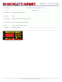
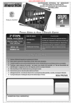
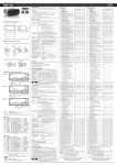
DOC U131V8
Manuale utente MI 1000
Parametri
Nota
S__
Descrizione
Min
Max
Default
Unit
Conservazione
St_
Temperatura e umidità
_t0
set point di temperatura
-55
145
2
_tb
banda neutra
0
50
0
°C
_td
differenziale
0
50
0.2
°C
_tH
massimo set point di temperatura dal pannello slave
-55
145
45
°C
_tL
minimo set point di temperatura dal pannello slave
-55
145
-55
°C
_i0
set point di umidità
0
100
85
%
_ib
banda neutra
0
50
0
%
_id
differenziale
0
50
5
%
_iH
massimo set point di umidità dal pannello slave
0
100
100
%
_iL
minimo set point di umidità dal pannello slave
0
100
0
%
SA_
Ricambio aria
SAH
abilita
oFF
on_
oFF
SA0
ritardo immediato
0
194 4:20:15
0
SAd
durata
0
194 4:20:15
30:00
dd hh:mm:ss
SAP
periodo
0
194 4:20:15
12:00:00
dd hh:mm:ss
SAh
abilita scorciatoia per il ricambio aria forzato
SAF
durata ricambio forzato
SAo
Fd_
(1)
(2)
on_
on_
0
194 4:20:15
30:00
oFF
on_
oFF
/
dd hh:mm:ss
/
Fd0
ritardo immediato prima del prossimo sbrinamento
0
194 4:20:15
0
dd hh:mm:ss
Fdd
durata
0
194 4:20:15
30:00
dd hh:mm:ss
Fdg
gocciolamento
0
194 4:20:15
2:00
dd hh:mm:ss
FdE
ritardo ventole
0
194 4:20:15
15:00
dd hh:mm:ss
FdP
periodo complessivo dello sbrinamento
0
194 4:20:15
4:00:00
dd hh:mm:ss
Fd1
durata impulsi ventole evaporat (unità di 0.001 s - selez 0 per disabilitare la funzione)
0
255
0
Fd2
periodo impulsi ventole evaporatore
0
194 4:20:15
1:00
/
dd hh:mm:ss
Sbrinamento forzato
FFh
abilita scorciatoia da tastiera per lo sbrinamento forzato
FFd
durata
FFo
FP_
avvia/arresta sbrinamento forzato
oFF
on_
on_
0
194 4:20:15
30:00
/
oFF
on_
oFF
/
0
5
2
/
-55
146
6
°C
dd hh:mm:ss
Preferenze dello sbrinamento
FPt
Ft_
tipo: 0=nessuno / 1=pausa / 2=aria / 3=elettrico / 4=gas caldo / 5=pompa di calore
Temperature di sbrinamento
Ftt
(4)
avvia/arresta ricambio forzato
oFF
/
dd hh:mm:ss
Tempi di sbrinamento
FF_
(3)
°C
M__
sonda di arresto sbrinamento
Compressore
MU_
(5)
(6)
Pressostati
MLH
riavvio di bassa pressione
0
30
1.2
bar
MLL
arresto di bassa pressione
0
30
0.2
bar
MHH
arresto di alta pressione
0
30
16
bar
MHL
riavvio di alta pressione
0
30
14
bar
MUO
pressione differenziale olio
0
30
2
bar
oFF
on_
oFF
/
MUU
(7)
H__
pump down
caldo
HP_
Preferenze
HPP
metodo: 0=nessuno / 1=elettrico / 2=gas caldo / 3=pompa di calore / 4=pc interna
0
4
0
/
HPF
fonte: 0=dedicata / 1=sbrinamento / 2=luce
0
2
0
/
U__
Deumidificazione
UP_
(8)
Preferenze
UPP
refrigerazione e riscaldamento in contemporanea / in alternata
oFF
on_
oFF
/
UP1
in caso di contemporaneità forzare la refrigerazione/riscaldamento
oFF
on_
oFF
/
n__
Ventilatori
nc_
Condensatore
ncH
attiva le ventole in caso di stacco compressore per alta pressione
oFF
on_
on_
/
(9)
ncr
abilita la regolazione dei giri
oFF
on_
on_
/
(10)
ncU
velocità minima
0
255
40
/
ncd
minima differenza di pressione tra scarico e aspirazione
0
30
2
bar
n1H
attacco ventilatore nr. 1
0
30
10
bar
n1L
stacco ventilatore nr. 1
0
30
6
bar
oFF
on_
oFF
/
/
(11)
nE_
Evaporatore
nEH
c__
ventole in continuo
Porta e luce
cP_
Interruttore porta e ventole evaporatore
cPH
arresta le ventole a porta aperta
oFF
on_
on_
cPF
sospendi il timer di sbrinamento in caso di pausa sbrinamento per arresto ventole
oFF
on_
on_
cPd
ritardo riavvio automatico ventole
0
194 4:20:15
30:00
eb / c22 / file U131V8_Rev_01.xls / creation date 2010-08-12 / sheet It / page 1 / 10
/
dd hh:mm:ss
DOC U131V8
cI_
(12)
Luce
cIH
accendi la luce a porta aperta
oFF
on_
on_
/
cIo
spegni automaticamente la luce
oFF
on_
on_
/
ritardo spegnimento automatico
0
194 4:20:15
30
dd hh:mm:ss
oFF
on_
on_
/
0
255
0
/
°C
cId
v__
Valvola di espansione elettronica
vP_
(13)
Preferenze valvola di espansione
vPH
abilita
vPP
tipo di gas refrigerante: 0=R134A / 1=R404A / 2=R507A / 3=R22 / 4=R407C
vt_
Temperature valvola di espansione
(14)
vtt
surriscaldamento voluto
0
99
8
(15)
vtH
surriscaldamento massimo
0
99
12
°C
(16)
vtL
surriscaldamento minimo
0
99
6
°C
MOP
0
30
10
bar
vtU
vd_
Tempi valvola di espansione
(17)
vd1
periodo
0
194 4:20:15
8
dd hh:mm:ss
(18)
vd2
tempo di apertura
0
194 4:20:15
5
dd hh:mm:ss
(19)
vdd
rapidità di adattamento
0
255
8
/
°C
b__
Calibrazione sonde
b1_
Sonda 1
b1C
temperatura cella
b1A
attiva
b2_
-99
99
0
oFF
on_
on_
/
Sonda 2
b2C
temperatura sbrinamento
b2A
attiva
b3_
-99
99
0
oFF
on_
on_
°C
/
Sonda 3
b3C
temperatura aspirante
b3A
attiva
b4_
-99
99
0
oFF
on_
on_
°C
/
Sonda 4
b4C
temperatura sala macchine
b4A
attiva
b5_
-99
99
0
oFF
on_
on_
°C
/
Sonda 5
b5C
umidità
b5A
attiva
b6_
-99
99
0
oFF
on_
oFF
%
/
Sonda 6
b6C
alta pressione
b6A
attiva
b7_
-99
99
0
oFF
on_
on_
bar
/
Sonda 7
b7C
bassa pressione
b7A
attiva
b8_
-99
99
0
oFF
on_
on_
bar
/
Sonda 8
b8C
temperatura premente
b8A
attiva
b9_
-99
99
0
oFF
on_
on_
°C
/
Sonda 9
b9C
pressione olio
b9A
attiva
L__
-99
99
0
oFF
on_
oFF
bar
/
Allarmi e pausa
Lt_
Allarme termico
(20)
LtL
bassa temperatura
-55
145
-2
°C
(21)
LtH
alta temperatura
-55
145
14
°C
0
194 4:20:15
30:00
Ltd
LF_
ritardo
dd hh:mm:ss
Allarme termico con arresto completo
LFL
bassa temperatura
-55
145
-5
°C
LFH
alta temperatura
-55
145
20
°C
0
194 4:20:15
30:00
LFd
Li_
ritardo
dd hh:mm:ss
Allarme di umidità
LiL
bassa umidità
0
100
0
%
LiH
alta umidità
0
100
100
%
ritardo
0
194 4:20:15
30:00
Lid
Lj_
dd hh:mm:ss
Allarme di umidità con arresto completo
LjL
bassa umidità
0
100
0
%
LjH
alta umidità
0
100
100
%
ritardo
0
194 4:20:15
30:00
Ljd
LO_
dd hh:mm:ss
Allarme porta
LOH
abilita
oFF
on_
on_
LOd
ritardo
0
194 4:20:15
30:00
dd hh:mm:ss
ritardo minimo dell'allarme termico dopo l'apertura della porta
0
194 4:20:15
15:00
dd hh:mm:ss
LOt
LI_
/
Altri allarmi
L1H
abilita allarme su INP-1 (sicurezza compressore)
L1d
ritardo
L2H
abilita allarme su INP-2 (sicurezza evaporatore)
eb / c22 / file U131V8_Rev_01.xls / creation date 2010-08-12 / sheet It / page 2 / 10
oFF
on_
on_
0
194 4:20:15
30:00
oFF
on_
on_
/
dd hh:mm:ss
/
DOC U131V8
L2d
ritardo
L3H
abilita allarme su INP-3 (sicurezza sbrinamento)
L3d
ritardo
L5H
abilita allarme su INP-5 (fase compressore / relè termico)
L5d
ritardo
Lo_
194 4:20:15
30:00
on_
on_
dd hh:mm:ss
0
194 4:20:15
30:00
oFF
on_
on_
0
194 4:20:15
1
oFF
on_
oFF
/
0
194 4:20:15
5:00
dd hh:mm:ss
/
dd hh:mm:ss
/
dd hh:mm:ss
On / stand-by status
Loo
(22)
0
oFF
d__
stato attuale: stand-by / on
Ritardi
dF_
Ritardo all'avvio
dF4
P__
ritardo relè 4 - compressore
Preferenze del master
Pd_
Indirizzi di rete
PdM
indirizzo del master sulla rete verso il PC
0
254
1
/
PdS
numero di slave collegati a questo master
1
2
2
/
0
6
0
/
PO_
Assegnamento degli output
PO2
I__
relè out-2 assegnato a: 0=allarme / 1=riscaldamento / 2=umidificatore / 3=ricambio aria
Funzioni di input-output
IA_
Input analogici
IA1
temperatura cella
-55
145
-55
°C
IA2
temperatura sbrinamento
-55
145
-55
°C
IA3
temperatura aspirante
-55
145
-55
°C
IA4
temperatura sala macchine
-55
145
-55
°C
IA5
umidità
0
100
0
%
IA6
alta pressione
0
30
0
bar
IA7
bassa pressione
bar
IA8
temperatura premente
IA9
pressione olio
Id_
30
0
145
-55
°C
0
30
0
bar
Input digitali
Id1
sicurezza mc
oFF
on_
oFF
/
Id2
sicurezza evaporatore
oFF
on_
oFF
/
Id3
sicurezza sbrinamento
oFF
on_
oFF
/
Id4
porta chiusa
oFF
on_
oFF
/
Id5
fase / relè termico
oFF
on_
oFF
/
oFF
on_
oFF
/
OS_
Stato della macchina
OSn
OA_
ventole evaporatore sotto arresto per apertura porta
Output analogici
LLA
allarme attuale (0= nessun allarme)
0
255
0
/
OA1
condensatore
0
255
0
/
OA2
umidità - 4...20 mA
0
255
0
/
Od_
(23)
0
-55
Output digitali
Od1
solenoide
oFF
on_
oFF
/
Od2
caldo
oFF
on_
oFF
/
Od3
luce
oFF
on_
oFF
/
Od4
compressore
oFF
on_
oFF
/
Od5
evaporatore
oFF
on_
oFF
/
Od6
sbrinamento
oFF
on_
oFF
/
Od7
allarme - eventualmente connesso ad OUT-2
oFF
on_
oFF
/
Od8
produttore di vapore - eventualmente connesso ad OUT-2
oFF
on_
oFF
/
Od9
ricambio aria - eventualmente connesso ad OUT-2
oFF
on_
oFF
/
1
254
1
/
E__
Preferenze dello slave
Ed_
Indirizzo di rete
EdS
EY_
indirizzo dello slave per la rete locale verso il master
Display
EYY
mostra: 1=temperatura cella / 2=IA2 / 3=IA3 ...
1
9
1
/
EYr
attiva la rotazione del display: 0=off / 1=tutti / 2=selezionati
0
2
0
/
E0_
Funzioni riguardo la rotazione del display quando EYr=1
E0d
durata della visualizzazione dell'etichetta durante la rotazione
0
255
1
/
E0E
durata della visualizzazione del valore durante la rotazione
0
255
2
/
E1_
Funzioni riguardo la rotazione del display quando EYr=2 (ripetute per ogni parametro)
E1d
durata della visualizzazione dell'etichetta durante la rotazione
E1t
testo dell'etichetta durante la rotazione
E1E
E2_
durata della visualizzazione del valore durante la rotazione
0
255
0
/
---
---
rM=
/
0
255
6
/
Funzioni riguardo la rotazione del display quando EYr=2 (ripetute per ogni parametro)
E2d
durata della visualizzazione dell'etichetta durante la rotazione
E2t
testo dell'etichetta durante la rotazione
E2E
durata della visualizzazione del valore durante la rotazione
E3_
0
255
1
/
---
---
dE=
/
0
255
0
/
Funzioni riguardo la rotazione del display quando EYr=2 (ripetute per ogni parametro)
E3d
durata della visualizzazione dell'etichetta durante la rotazione
E3t
testo dell'etichetta durante la rotazione
E3E
durata della visualizzazione del valore durante la rotazione
eb / c22 / file U131V8_Rev_01.xls / creation date 2010-08-12 / sheet It / page 3 / 10
0
255
1
/
---
---
SU=
/
0
255
0
/
DOC U131V8
E4_
Funzioni riguardo la rotazione del display quando EYr=2 (ripetute per ogni parametro)
E4d
durata della visualizzazione dell'etichetta durante la rotazione
E4t
testo dell'etichetta durante la rotazione
E4E
durata della visualizzazione del valore durante la rotazione
E5_
255
1
/
---
Er=
/
0
255
0
/
Funzioni riguardo la rotazione del display quando EYr=2 (ripetute per ogni parametro)
E5d
durata della visualizzazione dell'etichetta durante la rotazione
E5t
testo dell'etichetta durante la rotazione
E5E
durata della visualizzazione del valore durante la rotazione
E6_
0
255
1
/
---
---
rH=
/
0
255
4
/
Funzioni riguardo la rotazione del display quando EYr=2 (ripetute per ogni parametro)
E6d
durata della visualizzazione dell'etichetta durante la rotazione
E6t
testo dell'etichetta durante la rotazione
E6E
durata della visualizzazione del valore durante la rotazione
E7_
0
255
1
/
---
---
HP=
/
0
255
0
/
Funzioni riguardo la rotazione del display quando EYr=2 (ripetute per ogni parametro)
E7d
durata della visualizzazione dell'etichetta durante la rotazione
E7t
testo dell'etichetta durante la rotazione
E7E
durata della visualizzazione del valore durante la rotazione
E8_
0
255
1
/
---
---
LP=
/
0
255
0
/
Funzioni riguardo la rotazione del display quando EYr=2 (ripetute per ogni parametro)
E8d
durata della visualizzazione dell'etichetta durante la rotazione
E8t
testo dell'etichetta durante la rotazione
E8E
durata della visualizzazione del valore durante la rotazione
E9_
0
255
1
/
---
---
dI=
/
0
255
0
/
Funzioni riguardo la rotazione del display quando EYr=2 (ripetute per ogni parametro)
E9d
durata della visualizzazione dell'etichetta durante la rotazione
E9t
testo dell'etichetta durante la rotazione
E9E
durata della visualizzazione del valore durante la rotazione
Eb_
0
255
1
/
---
---
oI=
/
0
255
0
/
1
1
/
Funzioni riguardo al buzzer
EbH
1
2
3
4
5
6
0
---
abilita il buzzer
0
Note list
Lo sbrinamento non è eseguito una seconda volta, se le sicurezze del compressore e dell'evaporatore non sono a posto
Il periodo di ogni ciclo include il tempo attivo + il tempo inattivo
I successivi sbrinamenti saranno allineati allo sbrinamento forzato
In caso di sbrinamento a gas caldo, entrambe IA2 e IA3 devono raggiungere la temperatura Ftt
Quando MLH<MLL, vi è un ritardo di 10*(MLL-MLH) secondi sul pr. di bassa. L'eventuale riavvio per pumpdown è a MLH+1 bar.
Tempo fisso 120 s e riarmo manuale
7 Se attivo, un algoritmo di pump down intelligente coordina la solenoide, l'evaporatore e il mc. Vi è un ritardo di 15 min tra i riavvii del mc. SeMLL=MLH non vi sono riavvii. Non v
8
9
10
11
12
13
14
15
16
17
18
19
20
21
22
La refrigerazione è disattivata sotto LtL mentre il riscaldamento è disattivato sopra LtH
Se disattivo, la ventola del condensatore funziona in on-off.
Attenzione: la regolazione dei giri può causare il guasto del motore elettrico o della scheda, soprattutto a velocità basse o medie.
Durante i primi 10 secondi di marcia, n1L è sostituito da (n1H+n1L)/2
Nessuna azione in caso di luce accesa dall'interno
In caso di valvola disattiva, la solenoide è attiva insieme al compressore, se il surriscaldamento supera vtL ovvero b3A è off
Attenzione: surriscaldamenti bassi causano ritorni di liquido
Surriscaldamenti superiori al massimo forzano l'apertura anticipata della valvola
Surriscaldamenti inferiori al minimo ritardano l'apertura della valvola
Attenzione: cicli brevi riducono la vita della valvola
Attenzione: tempi di apertura lunghi causano ritorni di liquido
Attenzione: alte velocità causano oscillazioni
Differenziale fisso 0.2°C
Differenziale fisso 0.2°C
Passando da stand-by a on e all'accensione, vi è un ritardo di 5 secondi in stand-by virtuale
B1
B2
B3
B4
B5
B6
Pulsante
esc-silenzio
su
on - stand-by
sinistra - luce
giù - sbrinamento
destra - menu
Funzione
Esce senza salvare - silenzia il cicalino
Navigazione nel menu verso l'alto
Passa da on a Stand-by e viceversa. Arresta e riavvia le ventole dell'evaporatore per ridurre il disagio dell'operatore in cella.
Navigazione a sinistra nel menu - accende e spegne la luce
Navigazione in basso nel menu - Forza lo sbrinamento immediato
Mostra e cambia il set point - navigazione a destra nel menù - entra nel menù
L1
L2
L3
L4
L5
L6
L7
Led
refrigerazione
evaporatore
sbrinamento
ricambio aria
riscaldamento
etilene
luce
Attivo durante la refrigerazione - lampeggia sotto ritardo
Attivo con l'evaporatore - lampeggia sotto ritardo
Attivo in sbrinamento o umidificazione - lampeggia sotto ritardo
Attivo con il ricambio aria - lampeggia sotto ritardo
Attivo con il riscaldamento - lampeggia sotto ritardo
Attivo con l'iniezione di etilene - lampeggia sotto ritardo
Attivo con la luce - lampeggia sotto ritardo di spegnimento
Funzione
Come …?
Descrizione operazione
Tenere premuto il pulsante B3.
In stand-by ogni output è disabilitato ad esclusione dell'illuminazione.
In stand-by i led da L1 a L6 lampeggiano, è possibile entrare nel menù e modificare i parametri.
Premere brevemente il pulsante B3.
Arrestare e riavviare
manualmente le ventole Quando le ventole dell'evaporatore sono arrestate, il display numerico lampeggia mentre i led continuano a indicare senza lampeggiare.
Tenere premuto B6 per accedere al menu. Navigare su e giù con B2 and B5. Selezionare i sottomenù con B6.
Cambiare i parametri con B2 e B5, premere B6 per confermare o uscire senza salvare mediante B4.
Entrare nel menù
di configurazione
Le variazioni avranno effetto solo dopo l'uscita dal menù mediante la pressione di B4 più volte.
Premere B1 per uscire immediatamente senza salvare.
Mostrare/modificare il Entrare in programmazione e modificare _t0.
set point
Scorciatoia da tastiera: premere brevemente B6 - il display mostra il set point - cambiare e confermare con B6
Passare da stand-by a
on e viceversa
eb / c22 / file U131V8_Rev_01.xls / creation date 2010-08-12 / sheet It / page 4 / 10
DOC U131V8
Forzare un ric aria
Forzare uno sbrinam
Pulsante da premere
B5
B6 B2
A01
A02
A03
A04
A05
A06
A07
A08
A09
A10
A11
A12
A13
A14
A97
A98
A99
Allarme
bassa temperatura
alta temperatura
allarme mc
allarme evap
allarme sbrin
porta aperta
fase mc
stop di bassa temp
stop di alta temp
pressione olio
bassa umidità
alta umidità
stop di bassa umid
stop di alta umid
fuori range
nessun colleg.
perso colleg.
Display
- - - 3 lineette
. . . 3 punti
Tenere premuti B6+B2.
Tenere premuto B5.
Descrizione scorciatoia - tenere premuti i tasti per 5 s circa
sbrinamento immediato
ricambio aria forzato
Descrizione allarme
Superata la soglia di minima temperatura
Superata la soglia di massima temperatura
Sicurezza compressore / pressostato di alta
Stacco relè termico evaporatore
Intervento sicurezza sbrinamento
Porta aperta
Allarme relè termico compressore o mancanza di fase
Superata la soglia di minima temperatura con arresto completo
Superata la soglia di massima temperatura con arresto completo
Allarme di minima pressione olio - reset manuale
Superata la soglia di minima umidità
Superata la soglia di massima umidità
Superata la soglia di minima umidità - arresto completo
Superata la soglia di massima umidità - arresto completo
L'indirizzo dello slave EdS potrebbe essere fuori dal range del master che va da 1 a PdS
Lo slave non riceve alcun messaggio dal master
Lo slave ha perso la comunicazione con il master
Descrizione dello stato
Slave in ricezione dal master
Slave in trasmissione al master
Posizione pulsanti e led
L1 L2 L3 L4 L5 L6
B1
B2
B4
B5
L7
B3
Set
B6
eb / c22 / file U131V8_Rev_01.xls / creation date 2010-08-12 / sheet It / page 5 / 10
DOC U131V8
User Manual of H422V8
Parameter
Rem
S__
Description
Min
Max
Default
Unit
Functions about storage
St_
Functions about storage temperature
_t0
storage room temperature
-55
145
2
_tb
dead band
0
50
0
°C
_td
differential
0
50
0.2
°C
_tH
maximum set point of temperature from slave keyboard
-55
145
45
°C
_tL
minimum set point of temperature from slave keyboard
-55
145
-55
°C
_i0
storage room humidity
0
100
85
%
_ib
dead band
0
50
0
%
_id
differential
0
50
5
%
_iH
maximum set point of humidity from slave keyboard
0
100
100
%
_iL
minimum set point of humidity from slave keyboard
0
100
0
%
SA_
Functions about air renew during storage
SAH
enable air renew during storage
oFF
on_
oFF
SA0
immediate delay before first air renew
0
194 4:20:15
0
SAd
on-time duration in the air renew cycle
0
194 4:20:15
30:00
dd hh:mm:ss
SAP
period of air renew cycle
0
194 4:20:15
12:00:00
dd hh:mm:ss
SAh
enable forced air renew by keyboard short cut
SAF
forced air renew duration
SAo
Fd_
(1)
(2)
on_
on_
0
194 4:20:15
30:00
oFF
on_
oFF
/
dd hh:mm:ss
/
Fd0
immediate delay before next defrost
0
194 4:20:15
0
dd hh:mm:ss
Fdd
on-time duration of the defrost
0
194 4:20:15
30:00
dd hh:mm:ss
Fdg
dripping time after defrost
0
194 4:20:15
2:00
dd hh:mm:ss
FdE
evaporator fan activation delay after the defrost
0
194 4:20:15
15:00
dd hh:mm:ss
FdP
overall period of the defrost
0
194 4:20:15
4:00:00
dd hh:mm:ss
Fd1
evaporator fan pulse duration (0.001 s units - select 0 for no pulse during defrost)
0
255
0
Fd2
evaporator fan pulse period
0
194 4:20:15
1:00
/
dd hh:mm:ss
Functions about forced defrost
FFh
enable forced defrost by keyboard short cut
FFd
forced defrost duration
FFo
FP_
start immediate forced defrost
oFF
on_
on_
0
194 4:20:15
30:00
/
oFF
on_
oFF
/
0
5
2
/
-55
146
6
°C
dd hh:mm:ss
Functions about defrost preference
FPt
Ft_
defrost type: 0=none / 1=pause / 2=air / 3=electric / 4=hot gas / 5=heat pump
Functions about defrost temperature
Ftt
(4)
start / stop forced air renew
oFF
/
dd hh:mm:ss
Functions about defrost duration and timing
FF_
(3)
°C
M__
defrost probe stop temperature
Functions about compressor
MU_
(5)
(6)
Functions about pressure switches
MLH
low pressure safety restart ( similar to Danfoss KP15 lp set point )
0
30
1.2
bar
MLL
low pressure safety stop ( similar to Danfoss KP15 lp set point - differential )
0
30
0.2
bar
MHH
high pressure safety stop ( similar to Danfoss KP15 hp set point )
0
30
16
bar
MHL
high pressure safety restart ( similar to Danfoss KP15 hp set point - differential )
0
30
14
bar
MUO
minimum oil differential pressure
0
30
2
bar
oFF
on_
oFF
/
MUU
(7)
H__
pump down
heating
HP_
Heating preference
HPP
heating method: 0=none / 1=electric / 2=hot gas / 3=heat pump / 4=intern heat p
0
4
0
/
HPF
heating source: 0=dedicated heating / 1=defrost / 2=light
0
2
0
/
U__
Dehumidification
UP_
(8)
Dehumidification preference
UPP
concurrent refrigeration and heating / alternate refrigeration and heating
oFF
on_
oFF
/
UP1
during concurrent run force active: refrigeration / heating
oFF
on_
oFF
/
n__
Functions about fans
nc_
Functions about condenser fans
ncH
enable condenser fans when compressor is off and discharge pressure is over maximum
oFF
on_
on_
/
(9)
ncr
enable condenser fans speed regulation
oFF
on_
on_
/
(10)
ncU
fan minimum speed
0
255
40
/
ncd
minimum pressure difference between discharge and suction
0
30
2
bar
n1H
fan 1 start pressure ( similar to Danfoss KP5 set point ) - active just when ncr is oFF
0
30
10
bar
n1L
fan 1 stop pressure ( similar to Danfoss KP5 set point - differential )
0
30
6
bar
oFF
on_
oFF
/
/
(11)
nE_
Functions about evaporator fans
nEH
c__
enable evaporator fans when refrigeration is off
Functions about door and light
cP_
Door switch and evaporator fan
cPH
stop evaporator fans when door is open
oFF
on_
on_
cPF
pause defrost timer when air defrost is suspended by evaporator fan stop
oFF
on_
on_
cPd
delay of fan automatic switch on
0
194 4:20:15
30:00
eb / c22 / file U131V8_Rev_01.xls / creation date 2010-08-12 / sheet En / page 6 / 10
/
dd hh:mm:ss
DOC U131V8
cI_
(12)
Functions about light
cIH
switch on the light when the door is open and off when closed
oFF
on_
on_
/
cIo
switch off the light automatically if it has been switched on from outside
oFF
on_
on_
/
0
194 4:20:15
30
dd hh:mm:ss
oFF
on_
on_
/
0
255
0
/
°C
cId
v__
delay of light automatic switch off
Functions about electronic expansion valve
vP_
(13)
Functions about electronic expansion valve preference
vPH
enable electronic expansion valve
vPP
refrigerant gas type: 0=R134A / 1=R404A / 2=R507A / 3=R22 / 4=R407C
vt_
Functions about electronic expansion valve temperature
(14)
vtt
wanted overheating (similar to Danfoss thermostatic overheating spring regulation)
0
99
8
(15)
vtH
maximum overheating
0
99
12
°C
(16)
vtL
minimum overheating
0
99
6
°C
maximum pressure allowed in the suction line (similar to Danfoss MOP)
0
30
10
bar
vtU
vd_
Functions about electronic expansion valve timing
(17)
vd1
on-off duty cycle duration
0
194 4:20:15
8
dd hh:mm:ss
(18)
vd2
on duty cycle duration when refrigeration starts (set to 0 to remember previous stop value)
0
194 4:20:15
5
dd hh:mm:ss
(19)
vdd
on duty cycle adaptation speed (low value for slow adaptation and small swinging)
0
255
8
/
°C
b__
Functions about probe calibration
b1_
Probe nr. 1
b1C
room temperature
b1A
enable probe
b2_
-99
99
0
oFF
on_
on_
/
Probe nr. 2
b2C
defrost temperature
b2A
enable probe
b3_
-99
99
0
oFF
on_
on_
°C
/
Probe nr. 3
b3C
suction temperature
b3A
enable probe
b4_
-99
99
0
oFF
on_
on_
°C
/
Probe nr. 4
b4C
engine room temperature
b4A
enable probe
b5_
-99
99
0
oFF
on_
on_
°C
/
Probe nr. 5
b5C
humidity
b5A
enable probe
b6_
-99
99
0
oFF
on_
oFF
%
/
Probe nr. 6
b6C
high pressure
-99
99
0
b6A
enable probe
oFF
on_
on_
b7_
bar
/
Probe nr. 7
b7C
low pressure
-99
99
0
b7A
enable probe
oFF
on_
on_
b8_
bar
/
Probe nr. 8
b8C
discharge temperature
b8A
enable probe
b9_
-99
99
0
oFF
on_
on_
°C
/
Probe nr. 9
b9C
oil pressure - eventually connected to AN-5
b9A
enable probe
L__
-99
99
0
oFF
on_
oFF
bar
/
Functions about alarm and stand-by
Lt_
Temperature alarm
(20)
LtL
low temperature alarm set point
-55
145
-2
°C
(21)
LtH
high temperature alarm set point
-55
145
14
°C
0
194 4:20:15
30:00
Ltd
LF_
alarm delay
dd hh:mm:ss
Full stop temperature alarm
LFL
low temperature alarm set point
-55
145
-5
°C
LFH
high temperature alarm set point
-55
145
20
°C
0
194 4:20:15
30:00
LFd
Li_
alarm delay
dd hh:mm:ss
Humidity alarm
LiL
low humidity alarm set point
0
100
0
%
LiH
high humidity alarm set point
0
100
100
%
alarm delay
0
194 4:20:15
30:00
Lid
Lj_
dd hh:mm:ss
Full stop humidity alarm
LjL
low humidity alarm set point
0
100
0
%
LjH
high humidity alarm set point
0
100
100
%
alarm delay
0
194 4:20:15
30:00
Ljd
LO_
dd hh:mm:ss
Door alarm
LOH
enable door alarm
oFF
on_
on_
LOd
door alarm delay
0
194 4:20:15
30:00
dd hh:mm:ss
temperature alarm minimum delay after door opening
0
194 4:20:15
15:00
dd hh:mm:ss
LOt
LI_
/
Other alarm inputs
L1H
enable digital input 1 alarm (compressor safety devices)
L1d
digital input 1 alarm delay
L2H
enable digital input 2 alarm (defrost safety thermostat)
eb / c22 / file U131V8_Rev_01.xls / creation date 2010-08-12 / sheet En / page 7 / 10
oFF
on_
on_
0
194 4:20:15
30:00
oFF
on_
on_
/
dd hh:mm:ss
/
DOC U131V8
L2d
digital input 2 alarm delay
L3H
enable digital input 3 alarm (heating safety thermostat)
L3d
digital input 3 alarm delay
L5H
enable digital input 5 alarm (compressor phase monitor / thermal overload relay)
L5d
digital input 5 alarm delay
Lo_
194 4:20:15
30:00
on_
on_
dd hh:mm:ss
0
194 4:20:15
30:00
oFF
on_
on_
0
194 4:20:15
1
oFF
on_
oFF
/
0
194 4:20:15
5:00
dd hh:mm:ss
/
dd hh:mm:ss
/
dd hh:mm:ss
On / stand-by status
Loo
(22)
0
oFF
d__
actual status: stand-by or on
Functions about delays
dF_
Delay from previous stop
dF4
P__
delay from stop to activation of relay nr. 4: compressor
Functions about master preferences
Pd_
Functions about network address
PdM
master address for global network communication
0
254
1
/
PdS
number of slaves connected to this master
1
2
2
/
0
6
0
/
PO_
Output assignment
PO2
I__
assign out-2 relay to: 0=alarm / 1=heating / 2=humidifier / 3=air renew
Functions about input-output and machine state (read only)
IA_
Analog input
IA1
room temperature
-55
145
-55
°C
IA2
defrost temperature
-55
145
-55
°C
IA3
suction temperature
-55
145
-55
°C
IA4
engine room temperature
-55
145
-55
°C
IA5
humidity
0
100
0
%
IA6
high pressure
0
30
0
bar
IA7
low pressure
bar
IA8
discharge temperature
IA9
oil pressure - eventually connected to AN-5
Id_
30
0
145
-55
°C
0
30
0
bar
Digital input
Id1
compressor hardware safety
oFF
on_
oFF
/
Id2
evaporator hardware safety
oFF
on_
oFF
/
Id3
defrost hardware safety
oFF
on_
oFF
/
Id4
door closed
oFF
on_
oFF
/
Id5
phase software safety
oFF
on_
oFF
/
oFF
on_
oFF
/
OS_
Machine status
OSn
OA_
evaporator fan stopped by door opening or manual control
Analog output
LLA
actual alarm - read only (0 means no alarm)
0
255
0
/
OA1
condenser
0
255
0
/
OA2
humidity - 4...20 mA
0
255
0
/
Od_
(23)
0
-55
Digital output
Od1
solenoid
oFF
on_
oFF
/
Od2
heating
oFF
on_
oFF
/
Od3
light
oFF
on_
oFF
/
Od4
compressor
oFF
on_
oFF
/
Od5
evaporator
oFF
on_
oFF
/
Od6
defrost
oFF
on_
oFF
/
Od7
alarm - eventually connected to OUT-2
oFF
on_
oFF
/
Od8
steam producer - eventually connected OUT-2
oFF
on_
oFF
/
Od9
air renew - eventually connected to OUT-2
oFF
on_
oFF
/
1
254
1
/
E__
Functions about slave preferences
Ed_
Functions about network address
EdS
EY_
slave address for local network communication
Functions about display
EYY
input to show on display: 1=IA1 / 2=IA2 ...
1
9
1
/
EYr
enable display rotation: 0=off / 1=all / 2=selected
0
2
0
/
E0_
Functions about display rotation, when EYr=1
E0d
duration of label display during rotation
0
255
1
/
E0E
duration of value display during rotation
0
255
2
/
E1_
Functions about display rotation, when EYr=2 (repeated for each parameter)
E1d
duration of label display during rotation
E1t
label text during rotation
E1E
E2_
duration of value display during rotation
0
255
0
/
---
---
rM=
/
0
255
6
/
Functions about display rotation, when EYr=2 (repeated for each parameter)
E2d
duration of label display during rotation
E2t
label text during rotation
E2E
duration of value display during rotation
E3_
0
255
1
/
---
---
dE=
/
0
255
0
/
Functions about display rotation, when EYr=2 (repeated for each parameter)
E3d
duration of label display during rotation
E3t
label text during rotation
E3E
duration of value display during rotation
eb / c22 / file U131V8_Rev_01.xls / creation date 2010-08-12 / sheet En / page 8 / 10
0
255
1
/
---
---
SU=
/
0
255
0
/
DOC U131V8
E4_
Functions about display rotation, when EYr=2 (repeated for each parameter)
E4d
duration of label display during rotation
E4t
label text during rotation
E4E
duration of value display during rotation
E5_
255
1
/
---
Er=
/
0
255
0
/
Functions about display rotation, when EYr=2 (repeated for each parameter)
E5d
duration of label display during rotation
E5t
label text during rotation
E5E
duration of value display during rotation
E6_
0
255
1
/
---
---
rH=
/
0
255
4
/
Functions about display rotation, when EYr=2 (repeated for each parameter)
E6d
duration of label display during rotation
E6t
label text during rotation
E6E
duration of value display during rotation
E7_
0
255
1
/
---
---
HP=
/
0
255
0
/
Functions about display rotation, when EYr=2 (repeated for each parameter)
E7d
duration of label display during rotation
E7t
label text during rotation
E7E
duration of value display during rotation
E8_
0
255
1
/
---
---
LP=
/
0
255
0
/
Functions about display rotation, when EYr=2 (repeated for each parameter)
E8d
duration of label display during rotation
E8t
label text during rotation
E8E
duration of value display during rotation
E9_
0
255
1
/
---
---
dI=
/
0
255
0
/
Functions about display rotation, when EYr=2 (repeated for each parameter)
E9d
duration of label display during rotation
E9t
label text during rotation
E9E
duration of value display during rotation
Eb_
0
255
1
/
---
---
oI=
/
0
255
0
/
0
1
1
/
Functions about buzzer
EbH
1
2
3
4
5
6
0
---
enable buzzer
Note list
Defrost is not performed twice in case safety switches of mc or evaporator are not ok.
The period of each cycle includes on-time + off-time, that is the overall duration of the cycle.
Following defrost cycles will be aligned to the end of forced one.
In case of hot gas defrost, both IA2 and IA3 must reach Ftt
When MLH<MLL,there is a delay of 10*(MLL-MLH) seconds on lp switch. Eventual pumpdown restart is over MLH+1 bar.
Fixed time 120 s and manual reset.
7 When activated, a clever pump down algorithm coordinates the solenoid, the evaporator and the mc. There is a 15 minutes delay between mc restarts. When MLL=MLH there is
8
9
10
11
12
13
14
15
16
17
18
19
20
21
22
Forced refrigeration is disabled when room temperature is under LtL while forced heating is disabled over LtH
When speed regulation is off the fan is operated on-off.
Caution! Speed regulation can cause fan fault or electronic board fault. Low and average minimum speed can increase the risk.
During the first 10 seconds of speed regulation, the n1L is replaced by (n1H+n1L)/2
No action if the light is switched on from inside the room.
When off, the refrigeration solenoid is steadily on during cooling, as long as overheating is higher then vtL or b3A is off.
Caution! Low overheating causes liquid return and compressor damage
Overheating over the maximum forces valve anticipated opening
Overheating under the minimum delays valve opening
Caution! Short duty cycle reduces valve life
Caution! Low overheating causes liquid return and compressor damage
Caution! High adaptation speed causes swing in the suction line and damage to the compressor
The low temperature differential is fixed, and alarm status stops at 0.2 °C above the set point
The high temperature differential is fixed, and alarm status stops at 0.2 °C under the set point
Passing from stand-by to on and at power on, there is a 5 second delay spent in a virtual stand-by
B1
B2
B3
B4
B5
B6
Push button
esc-silence
up
on - stand-by
left - light
down - defrost
right - menu
Function
Exit without saving from any menu - Alarm buzzer silence
Up navigation in the menu
Toggle between on and stand-by - toggle evaporator fan stop
Left navigation in the menu - Switch light on and off
Down navigation in the menu - Force immediate defrost
Display and set temperature - Right navigation in the menu - Enter menu
L1
L2
L3
L4
L5
L6
L7
Led
cooling
evaporator fan
defrost
air renew
heating
ethylene
light
Function
On during cooling - blinking slowly during activation delay
On when evaporator fans are activated - blinking slowly during activation delay
On when defrost is activated - blinking slowly during activation delay
On when air renew is activated - blinking slowly during activation delay
On when heating is activated - blinking slowly during activation delay
On when ethylene is activated - blinking slowly during activation delay and during ripening
On when light is activated - blinking slowy during switch-off delay
How to ...?
Switch between
on and stand-by
Stop and restart
evaporator fans
Program the menu
Show / change
temperature
Operation description
In stand-by every output is disabled except light.
In stand-by leds L1 to L6 blink, counters continue to count, you can enter the menu and change parameters.
Press the B3 button to manually stop or restart evaporator fans.
When evaporator fans are stopped, the display blinks.
Keep pressed B6 to enter the menu. Navigate up and down with B2 and B5. Select the submenu by B6.
Change the parameter by B2 and B5, confirm it pressing B6 or go back without saving by B4.
The changes will have effect when you exit from programming pressing B4 repeatedly.
Press B1 to exit immediately without saving any parameter.
Enter programming - modify _t0 then confirm it.
Keyboard short cut: press shortly B6 - the display shows the current set point - change it and confirm it by B6
eb / c22 / file U131V8_Rev_01.xls / creation date 2010-08-12 / sheet En / page 9 / 10
DOC U131V8
Force an air renew
Force a defrost
Keep pressed B6+B2.
Keep pressed B5.
Buttons to press
B5
B6
A01
A02
A03
A04
A05
A06
A07
A08
A09
A10
A11
A12
A13
A14
A97
A98
A99
B2
Alarm
low temperature
high temperature
mc alarm
evaporator alarm
defrost alarm
door open
mc phase
low temp stop
high temp stop
oil pressure
low humidity
high humidity
low humid stop
high humid stop
out of range
no link
lost link
Display
- - - 3 dashes
. . . 3 dots
Shortcut description - keep pressed 5 seconds
Immediate defrost
Activate forced air renew
Alarm description
Minimum temperature exceeded
Maximum temperature exceeded
Pressure switch or other hardware compressor safety has disconnected
Evaporator thermal relay or other hardware evaporator safety has disconnected
Defrost thermostat of other hardware defrost safety has disconnected
Door open
Compressor overload/thermal relay disconnected or missing mains phase -manual reset
Minimum temperature exceeded - full plant stop
Maximum temperature exceeded - full plant stop
Minimum oil pressure alarm - manual reset
Minimum humidity exceeded
Maximum humidity exceeded
Minimum humidity exceeded - full plant stop
Maximum humidity exceeded - full plant stop
The slave address EdS might be out of the master range, the latter going from 1 to PdS
The slave does not receive any message from the master
The slave lost the communication with the master
Status description
Slave is receiving settings from master
Slave is sending settings to master
Led and push button location
L1 L2 L3 L4 L5 L6
B1
B2
B4
B5
L7
B3
Set
B6
eb / c22 / file U131V8_Rev_01.xls / creation date 2010-08-12 / sheet En / page 10 / 10