1
X
e
ree
RF
H425V2
User manual
doc H425V2
Contents
Contents
2
1 Parameter list
3
2 Parameter remarks
4
3 Alarm list
5
4 Slave alarm list
5
5 Button list
5
6 Led list
5
7 Soft command list
6
8 How to ...
6
9 Shortcut list
6
10 Led and push button location
6
The LATEX source of this document has been automatically produced by 4_13_22 on 2015-11-27
page 2\6
doc H425V2
1
Parameter list
Rem. Parameter
M__
MU_
ML0
MLb
MLd
1
2
3
4
5
6
7
8
9
MH0
MLH
MLL
MHH
MHL
MU1
MU2
MU3
Mut
MM1
MM2
MM3
MMH
MMd
n__
nc_
ncH
ncr
ncU
ncd
n1H
n1L
n2H
n2L
n3H
n3L
n4H
n4L
b__
b1_
b1C
b1A
b2_
b2C
b2A
b3_
b3C
b3A
b4_
b4C
b4A
b5_
b5C
b5A
b6_
b6C
b6A
b7_
b7C
b7A
b8_
b8C
b8A
L__
LI_
L1H
L1d
L2H
L2d
L3H
L3d
L4H
L4d
L5H
L5d
Description
Minimum Maximum Default Unit
Functions about compressor
Functions about pressure switches
suction low pressure regulation (similar to Danfoss RT1AL set point minus half of neutral
0.0
99.0
2.8 (gauge) bar
zone)
suction pressure regulation dead band (ML0 +/- MLb are the upper/lower limits)
0.0
99.0
0.5 bar
suction pressure regulation differential (loading at ML0+MLb+MLd / unl at ML0-MLb0.0
99.0
0.2 bar
MLd)
discharge (HP) pressure limit forcing the timed compressor unload
0.0
99.0
24.0 (gauge) bar
low pressure safety restart ( similar to Danfoss KP15 lp set point )
0.0
99.0
1.2 (gauge) bar
low pressure safety stop ( similar to Danfoss KP15 lp set point - differential )
0.0
99.0
0.2 (gauge) bar
high pressure safety stop ( similar to Danfoss KP15 hp set point )
0.0
99.0
28.0 (gauge) bar
high pressure safety restart ( similar to Danfoss KP15 hp set point - differential )
0.0
99.0
24.0 (gauge) bar
minimum oil differential pressure of compressor nr. 1
0.0
99.0
1.0 bar
minimum oil differential pressure of compressor nr. 2
0.0
99.0
1.0 bar
minimum oil differential pressure of compressor nr. 3
0.0
99.0
1.0 bar
minimum oil receiver temperature before opening the oil solenoid
-55.0
145.0
25.0 ◦ C
usage of mc nr. 1 output: 0=off / 1=on / 2=auto / 3=slave no / 4=slave nc / 5=kriwan
0
5
2 /
usage of mc nr. 2 output: 0=off / 1=on / 2=auto / 3=slave no / 4=slave nc / 5=kriwan
0
5
2 /
usage of mc nr. 3 output: 0=off / 1=on / 2=auto / 3=slave no / 4=slave nc / 5=kriwan
0
5
2 /
enable external load override on INP-4
oFF
_on
oFF /
external load override delay
0 194 4:20:15 1:00:00 dd hh:mm:ss
Functions about fans
Functions about condenser fans
enable condenser fans when compressor is off and discharge pressure is over maximum
oFF
_on
_on /
enable condenser fans speed regulation
oFF
_on
_on /
fan minimum speed
0
255
40 /
minimum HP-LP-difference to keep on fans
0.0
99.0
2.0 (gauge) bar
fan 1 start pressure ( similar to Danfoss KP5 set point ) - active just when ncr is oFF
0.0
99.0
10.0 (gauge) bar
fan 1 stop pressure ( similar to Danfoss KP5 set point - differential )
0.0
99.0
6.0 (gauge) bar
fan 2 start pressure
0.0
99.0
7.0 (gauge) bar
fan 2 stop pressure
0.0
99.0
5.0 (gauge) bar
fan 3 start pressure
0.0
99.0
8.0 (gauge) bar
fan 3 stop pressure
0.0
99.0
6.0 (gauge) bar
fan 4 start pressure
0.0
99.0
9.0 (gauge) bar
fan 4 stop pressure
0.0
99.0
7.0 (gauge) bar
Functions about probe calibration
Probe nr. 1
oil receiver temperature
-99.0
99.0
0.0 K
enable probe
oFF
_on
_on /
Probe nr. 2
discharge temperature
-99.0
99.0
0.0 K
enable probe
oFF
_on
_on /
Probe nr. 3
engine room temperature
-99.0
99.0
0.0 K
enable probe
oFF
_on
_on /
Probe nr. 4
mc1 oil pressure
-99.0
99.0
0.0 bar
enable probe
oFF
_on
_on /
Probe nr. 5
mc2 oil pressure
-99.0
99.0
0.0 bar
enable probe
oFF
_on
_on /
Probe nr. 6
mc3 oil pressure
-99.0
99.0
0.0 bar
enable probe
oFF
_on
_on /
Probe nr. 7
high pressure (HP)
-99.0
99.0
0.0 bar
enable probe
oFF
_on
_on /
Probe nr. 8
low pressure (LP)
-99.0
99.0
0.0 bar
enable probe
oFF
_on
_on /
Functions about alarm and stand-by
Other alarm inputs
enable mc1 alarm
oFF
_on
_on /
mc1 alarm delay
0 194 4:20:15 30:00 dd hh:mm:ss
enable mc2 alarm
oFF
_on
_on /
mc2 alarm delay
0 194 4:20:15 30:00 dd hh:mm:ss
enable mc3 alarm
oFF
_on
_on /
mc3 alarm delay
0 194 4:20:15 30:00 dd hh:mm:ss
enable external override alarm
oFF
_on
_on /
override alarm delay
0 194 4:20:15 1:00:00 dd hh:mm:ss
enable digital input 5 alarm (compressor phase monitor / thermal overload relay)
oFF
_on
_on /
digital input 5 alarm delay
0 194 4:20:15
1 dd hh:mm:ss
The LATEX source of this document has been automatically produced by 4_13_22 on 2015-11-27
page 3\6
doc H425V2
Rem. Parameter
Lo_
10
Loo
d__
dF_
dF4
dF5
dF6
dS4
dS5
dS6
P__
Pd_
PdM
PdS
Pb_
PbH
Pbd
Pbb
PbO
PPM
P2H
P2M
P2d
P3H
P3M
P3d
PO_
11
PO3
I__
IA_
IA1
IA2
IA3
IA4
IA5
IA6
IA7
IA8
Id_
Id1
Id2
Id3
Id4
Id5
OA_
LLA
OA1
OA2
Od_
12
Od1
Od2
Od3
Od4
Od5
Od6
Od7
Od8
E__
EY_
EYY
2
Description
Minimum Maximum Default Unit
On / stand-by status
actual status: stand-by or on
oFF
_on
oFF /
Functions about delays
Delay from previous stop
mc1 start delay
0 194 4:20:15
5:00 dd hh:mm:ss
mc2 start delay
0 194 4:20:15 10:00 dd hh:mm:ss
mc3 start delay
0 194 4:20:15 15:00 dd hh:mm:ss
mc1 stop delay
0 194 4:20:15
45 dd hh:mm:ss
mc2 stop delay
0 194 4:20:15
30 dd hh:mm:ss
mc3 stop delay
0 194 4:20:15
15 dd hh:mm:ss
Functions about master preferences
Functions about network address
master address for global network communication
0
254
1 /
number of slaves connected to this master
1
2
2 /
Suction pressure broadcast
enable suction pressure periodic broadcast over the PC net
oFF
_on
_on /
delay between pressure broadcast messages
0 194 4:20:15
30 dd hh:mm:ss
delay between latest received message and broadcasting start
0 194 4:20:15
2:00 dd hh:mm:ss
specify originating address in the pressure message
oFF
_on
_on /
become network master after Pbb delay
oFF
_on
oFF /
poll periodically second central unit for pressure broadcast
oFF
_on
oFF /
master address of second central unit
0
254
2 /
delay between pressure broadcast messages of second central unit
0 194 4:20:15
30 dd hh:mm:ss
poll periodically third central unit for pressure broadcast
oFF
_on
oFF /
master address of third central unit
0
254
3 /
delay between pressure broadcast messages of third central unit
0 194 4:20:15
30 dd hh:mm:ss
Output assignment
assign out-3 relay to: 0=condenser fan / 1=oil receiver solenoid / 2=alarm / 3=oil
0
3
0 /
heater / 4=subcooler / 5=off
Functions about input-output and machine state (read only)
Analog inputs
oil receiver temperature
-55.0
145.0
-55.0 ◦ C
discharge temperature
-55.0
145.0
-55.0 ◦ C
engine room temperature
-55.0
145.0
-55.0 ◦ C
oil pressure of mc1
0.0
30.0
0.0 (gauge) bar
oil pressure of mc2
0.0
30.0
0.0 (gauge) bar
oil pressure of mc3
0.0
30.0
0.0 (gauge) bar
high pressure (HP)
0.0
30.0
0.0 (gauge) bar
low pressure (LP)
0.0
30.0
0.0 (gauge) bar
Digital input
mc1 hardware safety
oFF
_on
oFF /
mc2 hardware safety
oFF
_on
oFF /
mc3 hardware safety
oFF
_on
oFF /
external override
oFF
_on
oFF /
phase software safety
oFF
_on
oFF /
Analog output
actual alarm - read only (0 means no alarm)
0
255
0 /
condenser
0
255
0 /
humidity - 4...20 mA
0
255
0 /
Digital output
condenser fan 2
oFF
_on
oFF /
condenser fan 3
oFF
_on
oFF /
condenser fan 4
oFF
_on
oFF /
compressor 1
oFF
_on
oFF /
compressor 2
oFF
_on
oFF /
compressor 3
oFF
_on
oFF /
oil receiver solenoid - eventually connected to OUT-3
oFF
_on
oFF /
alarm - eventually connected to OUT-3
oFF
_on
oFF /
Functions about slave preferences
Functions about display
input to show on display: 1=IA1 / 2=IA2 ...
0
255
1 /
Parameter remarks
Nr.
1
2
3
4
Remark
When MLH<MLL,there is a delay of 10*(MLL-MLH) seconds on lp switch. Eventual pumpdown restart is over MLH+1 bar.
Fixed time 120 s and manual reset.
In H425V3, starting from revision 03, when MU1 and MU3 are 5.0 and b4A and b6A are oFF, use 5NTC controller for compressors without oil
pump; connect HP probe on AN-6 and LP on AN-7.
Caution! Selection by manual override forces compressor to run whatever the high and low pressure; no safety is left except hardware ones. In
slave mode the output is used for partialization. In kriwan mode output is off for reset during stand-by.
The LATEX source of this document has been automatically produced by 4_13_22 on 2015-11-27
page 4\6
doc H425V2
Nr.
5
6
7
8
9
10
11
12
3
Remark
Caution! The external override drives the compressors ignoring high and low pressure; no safety is left except hardware ones. It is recommended
to close this contact passing through both contacts of a low pressure and high pressure switch like a kp15. The closed contact is interpreted
as "load" while the open contact is neutral. The delays dF4 through dF6 are respected.
After the delay elapsed, the override forces a load. Automatic reset.
When speed regulation is off the fan is operated on-off.
Caution! Speed regulation can cause fan fault or electronic board fault. Low and average minimum speed can increase the risk.
During the first 10 seconds of speed regulation, the n1L is replaced by (n1H+n1L)/2.
Passing from stand-by to on and at power on, there is a 5 second delay spent in a virtual stand-by.
In H425V3, starting from revision 02, when PO3 is 4, OUT-3 drives the subcooler liquid solenoid; AN-1 input is the subcooler suction
temperature; Mut is the wanted overheating, where 8.0 ◦ C means 8.0 ◦ C; maximum overheating is fixed at 99.0 ◦ C; minimum overheating is
fixed at 6.0 ◦ C; n4H is the refrigerant type, where 0.1 bar means R404A; n4L is the cycle period, where 0.8 bar means 8 s; H4H is the initial
on-time, where 0.5 bar means 5 s; H4L is the adaptation speed, where 0.8 bar means 8. To turn off the subcooler solenoid, set PO3 to 5. The
subcooler is enabled just when all of the available motorcompressors are on.
The minus sign on display ("-") signals that output is going to start after a delay.
Alarm list
Display
A01
A02
A03
A04
A05
A06
A07
A08
4
Push
B1
B2
B3
B4
B5
B6
6
Led
L1
L2
L3
L4
L5
L6
L7
Pressure switch, thermistors, or any other compressor safety device has disconnected.
Pressure switch, thermistors, or any other compressor safety device has disconnected.
Pressure switch, thermistors, or any other compressor safety device has disconnected.
The external override contact is driving the controller.
Compressor overload/thermal relay disconnected, or missing mains phase - manual reset.
Oil differential pressure remained under minimum value for 120 seconds - manual reset.
Oil differential pressure remained under minimum value for 120 seconds - manual reset.
Oil differential pressure remained under minimum value for 120 seconds - manual reset.
Slave alarm list
Display
/
5
Alarm
mc 1 alarm
mc 2 alarm
mc 3 alarm
external override
mc phase
mc 1 oil pressure
mc 2 oil pressure
mc 3 oil pressure
Alarm
none
This instrument has no slave alarm.
Button list
button
esc - silence
up
on / stand-by
left
down
right - menu - set
Function
Exit without saving from any menu - alarm buzzer silence.
Up navigation in the menu.
Toggle between on and stand-by.
Left navigation in the menu.
Down navigation in the menu.
Right navigation in the menu - display and modify the set point - enter menu.
Led list
compressor 1
compressor 2
compressor 3
condenser fan
condenser fan
condenser fan
condenser fan
1
2
3
4
Function
On during
On during
On during
On during
On during
On during
On during
compressor run - blinking slowly during activation and deactivation delay.
compressor run - blinking slowly during activation and deactivation delay.
compressor run - blinking slowly during activation and deactivation delay.
condenser run.
condenser run.
condenser run.
condenser run.
The LATEX source of this document has been automatically produced by 4_13_22 on 2015-11-27
page 5\6
doc H425V2
Soft command list
Soft command
8
Function
How to ...
How to ...
Switch between on and stand-by.
Program the menu.
Show or change pressure set.
9
Shortcut list
Buttons to press
/
10
Function
Keep pressed B3 button, to activate and deactivate stand-by. In stand-by every output is, leds from L1 to L7
blink, timers continue to count.
Keep pressed B6 to enter the menu. Navigate up and down with B2 and B5. Select the submenu by B6.
Change the parameter by B2 and B5, press B6 to confirm, or B4 to go back without saving. The changes
will have effect after the exit from programming pressing B4 repeatedly. Press B1 to exit immediately without
saving any parameter.
Press shortly B6 - the display shows the current set point - change it by B2 and B5, and confirm it by B6. As
alternative, enter the menu program as explained above, modify the parameter ML0, then confirm it.
Shortcut description - keep pressed 5 seconds
This instrument has no further shortcuts.
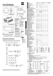
Led and push button location
ReFreeX
L1 L2 L3 L4 L5 L6
B1
B2
B3
B4
B5
B6
L7
Set
doc A112Y1
7
80% refrigerant reduction – full digital control – reduced winter consumption
80% di riduzione del refrigerante – controllo digitale completo – consumi invernali ridotti
The LATEX source of this document has been automatically produced by 4_13_22 on 2015-11-27
page 6\6