1
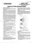
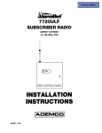
N2816V510/94
4208
No.
8.-POINT
REMOTE
POINT
MODULE
INSTALLATION INSTA’UCTIONS
GENEWL
The AOEMCO No. 4208 REMOTE POINT MODULE (RPM) is
an optional device used with point protection security
systems such as some VISTA controls.
Each RPM
intetiaces with and uniquely identifies up to eight protection
loops to the control. Although the No. 4208 will not, in any
way, expand the number of available protection points in a
system, it does afford a more simple installation
for
companies who homerun their sensors to the control or
who desire to group the sensors from an area of the
proteced premises onto one remote point module,
INSTALMTION
The No. 4208 installation procedures include programming,
mounting and wiring.
PROGWMIMING
Programmin$l the No. 4208 involves assigning a starting
sensor address by setiing four positions of a five-position
DIP switch. Each setting presats a series of eight sensor
loop control tiddresses (l-8, 9-16, 17-24, etc.). Use only
switch positicns 2, 3, 4, 5 to assign these numbers. DIP
switch position 1 selects fast (OFF) or slow (ON) response
for sensor loops 1 and 2.
All eight of the sensor loops are end-of-line
resistor
Important
Each No, 4208 used utilizes eight sequential
supervised, permitting the use of NO, or N,C. sensors on sensor ID numbers, whether or not all eight ara used. Do
each loop. All eight loops have normal (400 msec) not assign unused ID numbers to other modules. Refer to
response to sensor faults. However, two can be selected the control
panel Installation
Instructions
for the
(as a group) to have fast (1O msec) response. Six of the programming information for each point, and to determine
loops can be used with either mechanical or reed contacts the valid range of points for the system.
and the remaining WO can be used just with reed contacts.
NOTE
Switches 2-5 are show”
in ON position.
&
.
“:QwoN
.
.
1
@
d
LOOPS1 and2
RESPONSETIME
‘h
ON [SLOW
OFF(FAS~
@
(SHOWNOFfl
PRESETS TFIE LOOPS TO THESE SENSOR ADDRESSES
Loop Number = ---1
23
45
67
8
THIS SWITCH SE~lNG
DIP Switch Position
23
45
on
on
on
0.
1
0.
OFF
9
10
11
12
13
14
15
a7
2345
8 -+
,6
**
1
.“
. .
on
on
OFF
on
17
1S
19
20
21
22
23
24
on
on
OFF
OFF
25
2a
27
28
29
30
31
32_
on
OFF
on
on
33
34
35
36
37
3s
39
40_
S
e
n
on
OFF
on
OFF
41
42
43
44
45
46
47
4s_
s
~
0.
OFF
OFF
on
49
50
51
52
53
54
55
56_
on
OFF
OFF
OFF
57
5s
59
60
61
62
63
64_
:
OFF
on
on
on
85
66
67
68
69
70
71
72
OFF
on
on
OFF
73
74
75
76
77
7s
79
so
m
b
,
OFF
o“
OFF
o~
61
S2
83
84
S5
S6
S7
S6_
;
OFF
on
OFF
OFF
89
90
9t
92
93
94
95
98
OFF
OFF
on
on
97
9s
99
100
101
102
103
104
OFF
OFF
on
OFF
105
106
107
106
109
110
111
112
OFF
OFF
OFF
on
113
114
115
116
117
11s
119
120
OFF
OFF
OFF
OFF
121
122
123
124
125
126
127
N/A
“-119-16 is selected for VISTA, Loop 1 (Zone 9) INill be inactive.
“Do not select 1-S for VISTA
NOTE Consult the Control Panel [nstr.ctions to determine the vahd zone numbers for that control panel.
Diagram 1. DIP Switch Settillgs
r
1
MOUNTING AND WIRING
WARNING: All Dower should be disconnected before
proceeding.
1. MOUNT the No. 42~ in a climate controlled location.
a) Ramove tha front cover.
b) Draw the mounting holes, using the back cover as
a template. Drill the screw holes and install the
included mounting screws.
For UL MstedCommercialBurglav Usage
The No. 4208 must be mounted in a tmper protected
enclosure such as tha control ganel cabinet.
I
I
TERMINALS
CURRENT DRAW
LOOP RESPONSE
LOOP 1
1(+)
2(-)
4,7oo ohms 114W
1 Milliamp
Fast or Slow,
LOOP 2
3(+)
4(-)
4,7oo ohms l/4W
1 Milhamp
Fast or Slow’
LOOP 3
5(+)
6(-)
4,7oo ohms l/4W
1 Milfiamp
LOOP 4
7(+)
6(-)
4,7oo ohms l/4w
1 Milfiamp
9(+) 10 (-)
LOOP 5
4,700 ohms 114W
I
6
13(+) 14(-)
4,700 ohms 714W
LOOP 7
I 00P R
----
15(+) 16(-)
i 7(+)
R(.),
,,, i,-,
30,000 ohms 1/2W
[Pw
20
nnn ohms,- I,,-..
- .,...-,,,,
I 1 Mlhamp
100 Microamps
‘LOOP
I
EOL RESISTOR
2. WIRE the No. 420S by connecting the polling loop and
the protection loops (sea Diagram 2.) M~imum,
length of protection loop is 1200 feet using 22 gauge
twisted pair wire. See the instmctiOns wtich
accompany the control concerning polling loop
restrictions.
3. A~ACH
the wired No. 4208 to its mounting location
and tighten the mounting screws.
4. RECORD all system information on the cover’s label.
5. REPLACE tha covar.
I
[
1 Milhamp
hAi.rfi..U,mn=
,“. ,,,,.,
,,FG
inn
I Slow only
Slow only
I
~ Slow only
Slow only
I
Read or Mechanical
Reed or Mechanical
Reed or Mechanical
Raed or Mechanical
Slow only
CIA,.,-.1,,
“,”,
, _,, ,y
Reed only
Reed only
‘When FastiSlow response is selected, the selection affecta both Loops 1 & 2 as a pair.
For UL Listed Commemial Ffm
Usage:
Loops 7 and 8 may not be used.
Use N.O. conticts on loops 1-6.
Style B supewisa thesa loops using
I
model #EOL47 Fire fisted 4.7k
EOLR (purchased se~ately
packaged 16 per bag).
For UL Listed Commercial
Burgla~ Usag~
Use N.O. or N.C. contacts on loops
1-8. Supewise using EOLR
suppKed.
LOOP 1
(+)–
TO
POLLING
LOOP
LOOP 2
LOOP 6
LOOP 3
,o,oooohms~:-
LOOP 7
LOOP 4
,o,Oooohms*y:-
LOOP S
LOOP 5
(-)–
,,7000hms+~:-
DIAGRAM 2. k
420S SUMMARY OF CONNECTIONS
SPECIFICATIONS
Sensor Loop Response:
ENVIRONMENTAL
Temperature
Humidity
POWER CONSUMED:
Voltage Input
Current Drain:
DIMENSIONAL:
Width:
Height:
Depth:
-4” (-20”C)to+1560F
~0.c)
907. RH (non-condensing)
slow -
400 msec (all loops)
Fast -
10 msec
(option for Loops 1 and 2)
8-llV
16mA
Sensor Loop Currant Provided:
Loops 1-6
1 miltiamp
Loops 7, 8
100 microamps
3-7/6” (98mm)
~lt
(176mm)
1-3/6 (35mm)
Sensor Loop Wiring:
2
(sealed read sensors only)
Maximum of 1200 fact (365m.) of
No, 22 AWG (0.65 mm O, D,) wira
I
I
I
“FEDERAL
This equipment
statement
COMMUNICATIONS
has been tested to FCC requirements
COMMISSION
(FCC) STATEMENT,,
and has been found acceptable
for “se.
The FCC requires the f“}lOwin
for your i“formatiom
This equipment
generates
and uses radio frequency
energy and if not installed and used properly,
that is, in strict accordanc,
with the manufacturers
instructions, may cause intetierence to radio and television reception.
It has been type tested and
found to comply with the limits for a Class B computing device in accordance with the specifications
in Pati 15 of FCC Rules
which are designed to provide reasonable protection against such intefierence! in a residential installation,
However, there is
no guarantee that intetierence will not occur in a paticular
installation.
If this $?quipment does cause intetierence to radio or
television reception, which can be determined by turning the equipment off an,j on, the user is encouraged to by to correct
the intetierence
by o“e or more of the following measures
. If using an indoor antenna,
. Reorient
the receiving
. Move the antenna
have a quality outdoor antenna
antenna
until intetierence
or e~minatecl.
leads away from any wire runs to the controllcomm
. Plug the control/communicator
If necessa~,
installed.
is reduced
into a different
outlet so that it and the re!ceiver are on different
the user should consult the dealer or an experienced
The user or installer may find the following
booklet
unicator.
prepared
ratio/television
by the Federal
“lntetierence
technician
branch circuits.
for additional
Communications
Commission
HandbooW
This booklet is available from the U.S. Government Printing Ofice, Washi”gto”,
DC 20402.
The user shall not make any changes or modifications to the equipment unless a“thotized by the Insbllafion
User’s Manual.
Unauthorized
changes
or modifications
ADEMCO
Alarm Device
Manufacturing
Company,
suggestions.
helpful:
could “oid the user’s authority
LIMITED
to operate
Instructiorls
1
WAR~NTY
a Division of Pittway Corporation,
or
the equipment.
and its divisions,
subsidiaries
and affiliates
~Seller”), 165 Eileen Way, Syosset, New York 1 t 791, warrants its products to be in conformance with its own plans and
specifications
and to be free from defects in materials and workmanship under normal use and sewice for 18 months from
the date stamp control on the product or, for products not having an Ademco date stamp, for 12 months from date of “rigi”al
purchase unless the installation instructions or catalog sets fotih a shofler period, in which case the shotier petiod shall
aPPIY. Seller’s obligation shall be limited to repaiting or replacing, at its optior, free of charge for materials or labor, anY
product which is proved not in compliance with Seller’s specifications or provt?s defective in matetials or workmanship
under
normal use and sewice.
Seller shall have no ob~gation under this Limited Walrran~ or othemise if the product is altered or
improperly repaired or sewiced by anyone other than Ademco facto~ sewice,
For warranyt sewice,
transpotiation
prepaid, to Ademco Facto~ Sewice, 165 Eileen Way, Syosset, New York 11791.
THERE ARE NO WAR~NTIES,
EXPRESS
OR IMPLIED,
OF MERCHANTABILITY,
OR FITNESS
return product
FOR A PARTICULAR
PURPOSE OR OTHERWISE,
WHICH EKEND
BEYOND THE DESCRIPTION
ON THE FACE HEREOF.
IN NO CASE SHALL
SELLER BE LIABLE TO ANYONE FOR ANY CONSEQUENTIAL
OR INCIDENTAL DAMAGES FOR BR~CH
OF THIS OR ANY
OTHER WARRANW,
EXPRESS OR IMPLIED, OR UPON ANY OTHER BASIS OIF LIABILITY
OR DAMAGE IS CAUSED BE THE SELLER’S OWN NEGLIGENCE OR FAULT.
WHATSOEVER,
EVEN IF THE LOSS
Seller does not represent that the products it sells may not be compromised
or circumventeti
that the products will prevent
any personal inju~ or prope~
loss by burgla~, robbe~, fire or othewis%
or that the products will in all caes
provide
adequate warning or protection.
Customer understands that a properly install!?d and maintained alarm may only reduce the
hsk of a burgla~, robbe~, fire or other events occurting without providing an :darm, but it is not insurance or a guarantee that
such will not occur or that there will be no personal inju~ or propetiy loss * a result. CONSEQUENTLY,
SELLER SHALL
HAVE NO LIABILITY FOR ANY PERSONAL INJURY, PROPERTY
PRODUCT FAILED TO GIVE WARNING.
HOWEVER, IF SELLER
DAMAGE OR OTHER LOSS BASED ON A CLAIM THE
IS HELD LIABLE, WHNHER
DIRECTLY OR INDIRECTI.Y,
FOR ANY LOSS OR DAMAGE ARISING UNDER THIS LIMITED WARRANTY OR, OTHERWISE,
REGARDLESS
OF CAUSE: OR
ORIGIN, SELLERS
MAXIMUM
LIABILITY SHALL NOT IN ANY CASE EXCEED lrHE PURCHASE PRICE OF THE PRODUCT,
WHICH SHALL BE THE COMPLETE AND EXCLUSIVE REMEDY AGAINST SELI.ER. This warranty replaces any previous
warranties and is the only warranw made by Seller on this product.
obligations of this Limited Warranty is authorized.
3
No increase
or alteration,
written or verbal, of the
---
AmRM DEVICE MANUFACTURINGCO.
A DIVISIONOF PITTWAYCORP.
165 EILEENWAY, SVOSSET,NY 1179,
COPYRIGHT01994 PInwAy CORPORATION
N2816V5 10/94