1
CS-60 User’s Manual
Note
With a wye-connected secondary, any two of the legs can be used
to provide 208V to the CS-60. For example, L1 & L2, or L1
& L3, or L2 & L3. Leave the unused leg open. Do not connect it
to a Neutral bar, or to Ground. Be sure the center point is
grounded to earth somewhere in the system.
CS-60 User’s Manual
Mounting Procedures
1
Locate the wall mounting position
of the EVSE:
•
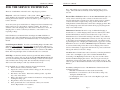
Figure 5. 240V 3-Phase, Delta-Connected, with center-tap on one leg.
•
L3 (NOT USED)
•
L1
120V
NEUTRAL
(NOT USED)
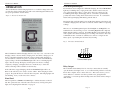
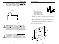
Figure 6. Wall mounting of CS-60.
Position the bottom of the
charge station 38 inches above
the ground.
The mounting holes are spaced
16" apart to accommodate wall
studs.
If you do not have solid
structural framing on those
centers, you must provide an
adequate alternative mounting
surface for the EVSE.
2
Attach the charge station to the wall studs using (4) ¼ x 2 ½” lag screws.
3
Use a multi-set or equivalent if mounting on a concrete wall.
4
Remove the applicable knock-out in the charge station, push the power
leads through the hole, then connect the power conduit to the hole.
5
After mounting, continue the installation using the Wiring Instructions
beginning on Page 11.
240V
120V
L2
GND
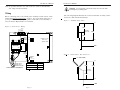
Figure 7. CS-60 Installation Template
Caution With the delta connection, one leg must be centertapped, and only the two phases on either side of the center tap
can be used. The two phases must both measure 120V to neutral.
The third line (L3) of the delta is 208V, with respect to neutral,
and is sometimes referred to as a “stinger”. Do not use this third
line! Consult the transformer manufacturer’s literature to be
sure the single leg can supply the required power..
Caution A 3-phase delta-connected transformer secondary
without a center-tap on one leg is not usable with the CS-60.
No “neutral” point is available to be connected to ground for
ground-fault protection, and the CS-60 will not allow the
contactor to close if it does not sense the presence of a ground
wire connected to a “neutral” point on the transformer secondary.
Page 9
Page 10