1
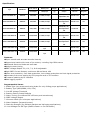
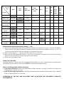
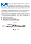
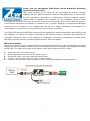
Thank you for purchasing ZTW Gecko Series Brushless Electronic Speed Controllers (ESC). High power systems for RC model can be very dangerous and we strongly suggest that you read this manual carefully. ZTW Model have no control over the use, installation, application, or maintenance of these products, thus no liability shall be assumed nor accepted for any damages, losses of costs resulting from the use of this item. Any claims arising from the operating, failure or malfunctioning etc. will be denied. We assume no liability for personal injury, property damage or consequential damages resulting from our product or our workmanship. As far as is legally permitted, the obligation for compensation is limited to the invoice amount of the product in question. The ZTW ESC’s high power BEC has been specifically designed for extreme aerobatics and therefore has the capability to support the higher momentary peak demand loads to eliminate the possibility of unwanted shutdowns, and is also capable of supporting continuous simultaneous multiple servo operations typically found in CCPM equipped hardcore 3D E-helicopters. Wires Connection: The speed controller can be connected to the motor by soldering directly or with high quality connectors. Always use new connectors, which should be soldered carefully to the cables and insulated with heat shrink tube. The maximum length of the battery pack wires shall be within 6 inches. Solder controller to the motor wires. Solder appropriate connectors to the battery wires. Insulate all solder connectors with heat shrink tubes. Plug the “JR” connector into the receiver throttle channel. Controller Red and Black wires connects to battery pack Red and Black wires respectively. 1 Specification: Type Gecko 45A SBEC 5A Cont./Burst Battery cell Weight Current(A) NiXX/Lipo (g) 45A/65A 5-18NC/2-6Lipo BEC Size(mm) User W*L*H Program 33*59*11.5 Yes 33*69*11.5 Yes 33*66*16 Yes 46*65*16.6 Yes 46*65*16.6 Yes 46*65*16.6 Yes 46*65*16.6 Yes PN#Model 4045201 Output 5.0V,6.0V adjustable /5A 5.0V,6.0V,7.4V, Gecko 65A SBEC 8A 4065201 65A/85A 5-18NC/2-6Lipo 8.4Vadjustable /8A 5.0V,6.0V,7.4V, Gecko 85A SBEC 8A 4085201 85A/100A 5-18NC/2-6Lipo 8.4Vadjustable /8A 5.0V,6.0V,7.4V, Gecko 125A SBEC 8A 4125201 125A/150A 5-18NC/2-6Lipo 8.4Vadjustable /8A 5.0V,6.0V,7.4V, Gecko 155A SBEC 8A 4155201 155A/200A 5-18NC/2-6Lipo 8.4Vadjustable /8A Gecko 120A OPTO HV 4120401 120A/150A Gecko 150A OPTO HV 4150401 150A/180A 18-38NC/6-12 Lipo 18-38NC/6-12 Lipo Features: ◆Super smooth and accurate throttle linearity ◆Support and match with most of the motors, including high RPM motors ◆Advanced Governor Mode and soft start ◆Multiple motor timing ◆SBEC Voltage Output 5.0, 6.0, 7.4, 8.4V adjustable ◆High SBEC Current Output, continuous 8A and burst 16A ◆Power arm protection, over-heat protection, low-voltage protection and lost-signal protection ◆Secondary sub-menu setting by LCD program card or PC interface ◆Firmware updating by PC interface ◆Data logging system Programmable items: 1. Brake Type (we recommend using brake for only folding props applications) 2. Battery Type (NiCd/NiMH, LiPo, LiFe) 3. Cut-Off Voltage Threshold 4. Restore Factory Setup Defaults 5. Motor Timing (to enhance ESC efficiency and smoothness) 6. SBEC Voltage Output 7. Governor Mode (for helicopter applications) 8. Motor Rotation (forward/reverse) 9. Start-Up Strength (for delicate gearbox and helicopter applications) 10. Low Voltage Cut-Off Type (Reduce Power or Cut-Off Power) 2 Settings: 1. Brake Type: Brake Off/Soft Brake/Mid Brake/Hard Brake * Brake Off- Sets the propeller to freewheel when the throttle stick is at the minimum position. * Soft Brake Sets the propeller to the 30% of the brake when the throttle stick is at the minimum position (Recommended for folding props). * Mid Brake Sets the propeller to the 60% of the brake when the throttle stick is at the minimum position (Recommended for folding props). * Hard Brake Sets the propeller to the 100% of the brake when the throttle stick is at the minimum position (Recommended for folding props). 2. Battery type: NiCad/NiMh /LiPo / LiFe * NiCad/NiMH – Sets Low Voltage protection threshold for NiCad/NiMH cells. * LiPo – Sets Low voltage protection threshold for LiPo cells and automatically detects the number of cells within the pack. * LiFe – Sets Low Voltage protection threshold for LiFe cells. Note: Selecting the NiCad/NiMH option for the battery type, triggers the ESC to automatically set the cutoff threshold to the factory default of 60%.The cutoff threshold can then be subsequently altered through the Low Voltage protection function, if required. The ESC will read the initial voltage of the NiCad/NiMh pack once it is plugged in and the voltage read will then be used as a reference for the cut off voltage threshold. 3. Cut Off Voltage Threshold (Low Voltage Protection Threshold): 2.8V/50%/ 3.0V/60%/ 3.2V/65%/No Protection 1) For Li-xx packs- number of cells are automatically calculated and requires no user input apart from defining the battery type. This ESC provides 4 setting options for the low voltage protection threshold; 2.8V/ 3.0V/3.2V/No Protection. For example: the voltage cutoff options for an 11.1V/ 3 cell Li-Po pack would be 8.4V (Low)/ 9.0V (Med)/ 9.6V (High) 2) For Ni-xx/Life packs-low / medium / high cutoff voltages are 50%/60%/65% of the initial voltage of the battery pack. For example: A fully charged 6 cell NiMh pack’s voltage is 1.44V x 6=8.64V, when “LOW” cutoff voltage is set, the cutoff voltage is: 8.64V x 50%=4.3V and when “Medium” of “High” is set, the cutoff voltage is now 8.64V X 65%=5.61V. 4. Restore factory setup defaults: Restore- Sets the ESC back to factory default settings; Brake Type: Brake Off Battery Type: LiPo with Automatic Cell detective Cut Off Voltage Threshold: 3.0V/60% Motor Timing: Auto SBEC Voltage Output 5.0V Governor Mode: RPM OFF Motor Rotation: Forward Start Up Strength: 30% Low Voltage Cut Off Type: Reduce Power 5. Motor Timing : Auto, 2°, 8°, 15°, 22°, 30° * Auto – ESC determines the optimum motor timing automatically. * 2° and 8° – Set for most of in-runner motors. * 15° and 22° –Set for motors with 6 or more poles. * 30° – Setting for motors with more poles. 3 In most cases, automatic timing works well for all types of motors. However for high efficiency we recommend the Low timing setting for 2 pole motors (general in-runners) and high timing for 6 poles and above (general out-runners). For higher speed, High timing can be set. Some motors require different timing setups therefore we suggest you to follow the manufacturer recommended setup Note: Run your motor on the ground first after making any changes to your motor timing! 6. SBEC Voltage Output: 5.0V/6.0V/7.4V/8.4V for Gecko Series ESC above 45A. 5.0V/6.0V for Gecko 45A. There are the four different levels of SBEC voltage output can be selected. * The 1st Level: 5.0V * The 2nd Level: 6.0V * The 3rd Level: 7.4V * The 4th Level: 8.4V 7. Governor Mode (Heli Governor Mode) * RPM OFF * Soft Start: For 1st Soft Start, there will be 8-second delay from start to full rpm; For 2nd Soft Start, there will be 18-second delay from start to full rpm; Note: If the throttle is cut off after starting less 3 Seconds, then the next start will be as normal start. If the throttle is cut off after starting more than 3 Seconds, the next start will be as soft start. Governor Mode 1: There will be a 23-second delay from start to full rpm; If lower the throttle to the 80% position of the full throttle or lower than 80% position, the RPM would be definitely changed, the lost RPM will be detected and compensated automatically by the ESC that makes sure to keep the RPM at the same speed. (Note: This function is only for Low KV motor) Governor Mode 2: There will be a 23-second delay from start to full rpm; If lower the throttle to the 80% position of the full throttle or lower than 80% position, the RPM would be definitely changed, the lost RPM will be detected and compensated automatically by the ESC that makes sure to keep the RPM at the same speed. (Note: This function is only for High KV motor) Note 1: If the throttle is cut off after starting less 3 Seconds, then the next start will be as normal start. If the throttle is cut off after starting more than 3 Seconds, the next start will be as soft start. Note 2: Once the Governor Mode is enabled, the ESC’s Brake and Low Voltage Cutoff Type settings will automatically be reset to Brake Off and Reduce Power respectively, regardless of what settings they were previously set. Note 3: Lower 50,000 turns is considered as Low KV motor, 100,000-200,000 turns is considered as High KV motor. Formula: Pole’s qty of motor x KV value x Voltage= Motor turns For example: we test 8 pole motor 1040KV with 6S Lipo, its turns will be 8x1040KVx25v=208,000 turns, so you can choose Governor Mode 2. 8. Motor Rotation: Forward/ Reverse In most cases motor rotation is usually reversed by swapping two motor wires. However, in cases where the motor cables have been directly soldered the ESC cables, motor rotation can be reversed by changing the value of setting on the ESC. 9. Start up Strength *Low (10%-15%-20%) Sets ESC start up strength for the motors which needs low start up current *Mid (25%-30%-35%) Sets ESC start up strength for the motors which needs mid start up current *High (40%-45%-50%) Sets ESC start up strength for the motors which needs high start up current 10. Low Voltage Cut Off Type: Reduce Power / Cut Off Power 4 * Reduce Power – ESC reduces motor power when the pre-set Low Voltage Protection Threshold value is reached. (Recommended) * Cut Off Power – ESC instantly cuts motor power when the pre-set Low Voltage Protection Threshold value is reached. THE PROCEDURE AND INSTRUCTION OF THE PROGRAMMING BY TRANSMITTER 1. ENTERING THE PROGRAMMING MODE 2. SELECTING THE PROGRAMMABLE ITEM 3. SELECTING THE DESIRED VALUE OF THE PROGRAMMABLE ITEM 4. DISCONNECTING THE BATTERY PACK 1. ENTERING THE PROGRAMMING MODE 1).Switch your Transmitter ON and set the throttle stick to its maximum position. 2).Connect the battery pack to the ESC 3).Wait for about 2 seconds until you hear two short beeps (●● ●● ●● ●●) confirming that the ESC has now entered the programming mode. 2. SELECTING THE PROGRAMMABLE ITEM The Programming Mode is in Sequence, each Programmable Item is equivalent to an audible tone emitting for four times. You will hear 10 tones in a loop with the following sequence. When the desired tone for the Programmable Item is reached, move the throttle stick down to its minimum position. The motor will emit one special tone confirming the desired programmable item has been entered. 3. SELECTING THE DESIRED VALUE OF THE PROGRAMMABLE ITEM The motor has been emitting sequentially. If the desired value of the programmable item is reached, set the throttle stick to its maximum position. The motor will emit one special tone confirming the new setting has been stored. 4. DISCONNECTING THE BATTERY PACK. If you don’t want to go on to programming, disconnect the battery pack directly. If you want to go on to programming, keep waiting to the next programmable item to select the value you need. Note: You could also select the LED program card to program your desired function. Program card is as the option spare part, its programming procedure is described in the LED program card user manual. THE TONES WILL BE HEARD IN SEQUENCE AS FOLLOWS: 1 BeepBrake Type (1 short tone) 2 Beep-BeepBattery Type (2 short tone) 3 Beep-Beep-BeepCut off Voltage Threshold (3 short tone) 4 Beep-Beep-Beep-BeepRestore Factory Setup Defaults (4 short tones) 5 Beep----Motor Timing (1 long tone) 6 Beep-----BeepSBEC Voltage Output (1 long tone 1 short tone) 7 Beep-----Beep- BeepGovernor Mode (1 long tone 2 short tone) 8 Beep-----Beep- Beep- BeepMotor Rotation (1 long tone 3 short tone) 9 Beep-----Beep- Beep- Beep- BeepStart up Strength (1 long tone 4 short tone) 10 Beep----- Beep----Low Voltage Cut off Type (2 long tone) Remark: One long tone “Beep-----”is equal to five short tones “Beep-”. 5 Tone of value BEEP- BEEP- BEEP- BEEP- BEEP- BEEP- BEEPBEEP- BEEP- Brake Type Brake OFF Battery Type NiCd/NiMH LiPo LiFe 2.8V/50% 3.0V/60% 3.2V/65% No Protection Auto 2° 8° 15° 5.0V 6.0V 7.4V 8.4V Governor Mode RPM OFF 1st Soft Start 2nd Soft Start Motor Rotation Forward Reverse 10% 15% Low Voltage Cut Reduce Cut Off Off Type Power Power Cut Off Voltage Threshold Restore Factory Setup Defaults Motor Timing SBEC Voltage Output Start Up Strength Mid Brake BEEP----- BEEP- Prog.Item Soft Brake BEEP---BEEP- BEEP---BEEPBEEP- BEEP---BEEPBEEPBEEP- BEEP---BEEPBEEPBEEPBEEP- Hard Brake Restore 20% 22° Governor Governor Mode 1 Mode 2 25% 30% 30° 35% 40% 45% 50% FOR Example: Setting the motor timing ----15° 1). Switch your Transmitter ON and set the throttle stick to its maximum position. Connect the battery pack to the ESC and wait for about 2 seconds until you hear two sets of audible tone (●● ●● ●● ●●) confirming that the ESC has now entered the programming mode. 2). After hearing “Beep-----”, put the throttle sticker to its minimum. 3). After hearing “Beep-Beep-Beep-Beep-” ,put the throttle sticker to its maximum, the motor will emits special tones confirming the new setting has been stored. 4). Disconnect the battery pack. Using Your New ESC Improper polarity or short circuit will damage the ESC therefore it is your responsibility to double check all plugs for proper polarity and first fit BEFORE connecting the battery pack. Built-in Intelligent ESC Safety Functions 1. Over-heat protection: When the temperature of ESC exceeds 110 deg C, the ESC will reduce the output power to allow it to cool. 2. Lost Throttle signal protection: The ESC will automatically cut power to the motor when it detects a lost of throttle signal for 2 seconds. POWERING UP THE ESC FOR THE FIRST TIME & SETTING THE AUTOMATIC THROTTLE CALIBRATION 6 The ZTW ESC features Automatic Throttle Calibration to attain the smoothest throttle response and resolution throughout the entire throttle range of your transmitter. This step is done once to allow the ESC to “learn and memorize” your Transmitter’s throttle output signals and only repeated if you change your transmitter. 1. Switch your Transmitter ON and set the throttle stick to its maximum position. 2. Connect the battery pack to the ESC. Wait for about 2 seconds, the motor will beep for twice, then put the throttle in the minimum position, the motor will also beep, which indicates that your ESC has got the signal range of the throttle from your transmitter. The throttle is now calibrated and your ESC is ready for operation. NORMAL ESC START UP PROCEDURE 1. Switch your Transmitter ON and set the throttle to its minimum position. 2. Connect the battery pack to the ESC. 3. When the ESC is first powered up, it emits two sets of audible tones in succession indicating its working status. * The first set of tones denotes the number of cells in the LiPo pack connected to the ESC. (Three beeps (***) indicates a 3 cell LiPo pack while 4 beeps (****) indicates a 4 cell LiPo pack). * The second set of tones denotes Brake status (one beep (*) for Brake “ON” and two beeps (**) for Brake “OFF”). The ESC is ready for use now. General Safety Precautions Do not install the propeller (fixed wing) or drive pinion (helicopter) on the motor when you test the ESC and motor for the first time to verify the correct settings on your radio. Only install your propeller or pinion after you have confirmed that the settings on your radio is correct. ● Never use ruptured or punctured battery cells. ● Never use battery packs that are known to overheat. ● Never use short circuit battery or motor terminals. ● Always use proper insulation material for cable insulation. ● Always use proper cable connectors. ● Do not exceed the number of cells or servos specified by the ESC. Wrong battery polarity will damage the ESC and void the warranty. ● ● ● ● ● ● ● ● Install the ESC in a suitable location with adequate ventilation for cooling. This ESC has a built-in over temperature cutoff protection feature that will immediately cut power to the motor once the ESC temperature exceeds the 230 Deg F/ 110 Deg C high temperature limit. Use only batteries that are supported by the ESC and ensure the correct polarity before connecting. Switch your Transmitter ON and ensure the throttle stick is in the minimum position before connecting the battery pack. Never switch your transmitter OFF while the battery is connected to your ESC. Only connect your battery pack just before flying and do not leave your battery pack connected after flying. Handle your model with extreme care once the battery pack is connected and keep away from the propeller at all times. Never stand in-line or directly in front of any rotating parts. Do not immerse the ESC underwater or allow it to get wet while powered up. Always fly at a designated flying site and abide by the rules and guidelines set by your flying club. Trouble Shooting Trouble Possible Reason 7 Action Motor doesn’t work and there are no audible tones while servos The ESC throttle calibration has Set up the ESC throttle work properly after powering up been not set up. calibration. Poor/loose Connection between Clean connector terminals or battery Pack and ESC. replace connector. ESC. Motor doesn’t work and no audible tone emitted after connecting the battery. Servos are not working either. Replace with a freshly charged No power battery pack Poor soldered connections (dry joints) Wrong battery cable polarity ESC throttle cable connected to receiver in the reverse polarity Faulty ESC Re-solder the cable connections Check and verify cable polarity Check the ESC cable connected to the ESC to ensure the connectors are in the correct polarity. Replace ESC Swap any two of the three cable connections between the ESC and Motor runs in reverse rotation Wrong cables polarity between the Motor or access the Motor the ESC and the motor. Rotation function via the ESC programming mode and change the pre-set parameters. Check proper operation of the radio equipment. Check the placement of the ESC and the Receiver and check the route of Lost throttle signal the receiver’s aerial and ESC cables to ensure there is adequate separation to prevent RF Motor stops running in flight. interference .Install a ferrite ring on the ESC’s throttle cable. Battery Pack voltage has reached the Low Voltage Protection threshold. Possible bad cable connection Land the model immediately and replace the battery pack. Check and verify the integrity of the cable connections The normal operation of the ESC may be susceptible to surrounding RF interference. Restart the ESC Motor restarts abnormally ESC Possible RF Interference at the to resume normal operation on Overheats flying field. the ground to verify recurrence. If the problem persists, test the operation of the ESC at a different flying field. 8 Inadequate Relocate the ESC to allow better Ventilation ventilation Use servos that are adequately Servos drawing too much current sized for the ESC. The maximum and over loading the ESC. BEC current drawn should be within the BEC limits. Over sized motor or prop Reduce Prop size or resize the motor Shenzhen ZTW Model Science & Technology Co., Ltd ADD: 5/F B, Block A4, Anle Industrial Estate, st. Hangcheng, Gushu, XiXiang, BaoAn, Shenzhen, China, 518001 TEL: +86 755 29120026, 29120036, 29120056-808 FAX: +86 755 29120016 Http://www.ztwoem.com E-mail: [email protected] 9