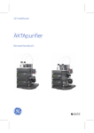
1
Ä K T A purifier
Installation G uide
18-1140-44
Important us er information
Trademarks
ÄK T A , UN IC O R N and Superloop are trademarks of
A mersham Biosciences or its subsidiaries.
!
M eaning: C onsult the instruction manual to avoid
personal injury or damage to the product or other
equipment.
WA R N I N G !
T he Warning sign is used to call attention to the
necessity to follow an instruction in detail to avoid
personal injury. Be sure not to proceed until the
instructions are clearly understood and all stated
conditions are met.
C AUT IO N !
T he C aution sign is used to call attention to instructions
or conditions that shall be followed to avoid damage to
the product or other equipment. Be sure not to proceed
until the instructions are clearly understood and all
stated conditions are met.
N ote
T he N ote sign is used to indicate information important
for trouble-free or optimal use of the product.
Should you have any comments on this instruction, we
will be pleased to receive them at:
A mersham Biosciences
SE –751 84 Uppsala
Sweden
W indows is a trademark of M icrosoft C orp.
Terms and C onditions of S ale
A ll goods and services are subject to the terms and
conditions of sale of the company within the A mersham
Biosciences group which supplies them. A copy
of these terms and conditions of sale is available on
request.
A ddres s es
A mersham Biosciences
SE -751 84 Uppsala
Sweden
A mersham Biosciences U K L imited
A mersham Place
L ittle C halfont
Bucks, H P7 9N A
E ngland
A mersham Biosciences
800 C entennial Avenue
PO Box 1327
Piscataway, N J 08855
USA
A mersham Biosciences E urope G mbH
Postfach 5480
D -79021 Freiburg
G ermany
© A mersham Biosciences 2000
– A ll rights reserved
____________________________________________________ Contents
Contents
1
About this installation guide ........................................... 1
2
Safety ................................................................................ 2
3
Pre-requisites ................................................................... 3
4
Installation overview ........................................................ 4
5
Installation of ÄKTApurifier ............................................ 5
5.1 Unpacking ................................................................. 5
5.2 Installing the computer and the cables ....................... 8
6
Installation test ................................................................. 9
6.1 Preparation of ÄKTApurifier ..................................... 9
6.2 Priming and purging Pump P-900 ............................ 10
6.3 Running the installation test method ....................... 12
6.4 Evaluating the installation test results ...................... 14
6.5 Correcting faulty evaluation results ......................... 17
7
Test record ..................................................................... 19
7.1 Gradient test result .................................................. 19
7.2 Step response test result ........................................... 19
7.3 UV response test result ............................................ 19
8
Installation record .......................................................... 20
9
Registration form ........................................................... 21
ÄKTApurifier
Installation Guide 18-1140-44 Edition AA
i
__________________________________ About this installation guide
1
1 About this installation guide
ÄKTA™ purifier is assembled and fully tested before shipping.
For safe transportation, however, some components have been secured
and thus need to be detached before the system can be tested and used.
Cables, capillaries, accessories, etc. are enclosed in paper boxes or in
Box-900 located at the top of the instrument pile.
This guide describes how to install ÄKTApurifier 10 and
ÄKTApurifier 100. The description is common for both systems, unless
otherwise is clearly stated in the contents. The differences are few and
indicated with divergent type face.
The guide is divided into two parts; one describing the installation and
one describing how to run the installation test. After the installation
procedure has been performed, your ÄKTApurifier is ready for
purification work.
For full details of specifications, methods, maintenance etc., refer to the
respective User Manuals and Instructions.
ÄKTApurifier
Installation Guide 18-1140-44 Edition AA
1
2
S afety ___________________________________________________
2 S afety
•
T he system is designed for indoor use only.
•
D o not use in a dusty atmosphere or close to spraying water.
R efer to Technical Specifications in the System M anual for detailed
environmental pre-requisites.
WA R N IN G ! T he individual instruments must not be opened by the
user. T hey contain high voltage circuits that can give a lethal electric
shock.
WA R N IN G ! M onitor UPC -900 uses high intensity ultra-violet light.
D o not disconnect the optical unit while the lamp is O N .
WA R N IN G ! Ä K TA purifier must be connected to a grounded mains
socket.
WA R N IN G ! T here must always be a sample loop or Superloop™
connected to ports 2 and 6 of the injection valve. T his prevents
liquid spraying out of the ports when switching the valve, which is
especially dangerous if hazardous chemicals are being used.
WA R N IN G ! Two people are required to lift the system.
WA R N IN G ! N ever block the ports on the outlet valve with stop
plugs, since this will create over-pressure and may result in injury.
WA R N IN G ! O nly spare parts approved or supplied by A mersham
Biosciences may be used for maintaining and servicing the
system.
WA R N IN G ! If the system is turned around or the fraction collector
removed, the external capillaries and other tubings may become
entangled in nearby objects and be pulled from their connections
causing leakage.
WA R N IN G ! N ever place waste containers on the top of the system.
If they become full and overflow, liquid may penetrate the system
causing a short-circuit.
2
Ä K T Apurifier
I nstallation G uide 18-1140-44 E dition A A
_____________________________________________ Pre-requisites
3
3 Pre-requisites
WARNING! ÄKTApurifier must be connected to a grounded mains
socket.
• Two people are recommended to lift ÄKTApurifier onto the
working bench.
• To install ÄKTApurifier, a working area of about 200 x 80 cm is
required.
• ÄKTApurifier requires 100-120/220-240 VAC, 50/60 Hz electrical
supply with safety grounding.
• Cutting pliers are recommended for cutting plastic straps.
• A waste flask.
• The installation test requires the following solutions:
- 1000 ml of distilled water for priming and purging the pump.
- 500 ml of 0.4% acetone in distilled water.
- 100 ml of 20% ethanol in distilled water.
ÄKTApurifier
Installation Guide 18-1140-44 Edition AA
3
4 Installation overview
_______________________________________
4 Installation overview
• Unpack ÄKTApurifier ................................................................. 5
• Detach secured items, and install items enclosed .......................... 6
• Unpack and install the computer.................................................. 8
• Connect mains power cabling ...................................................... 8
• Connect UniNet 1 data communication chain cabling.................. 8
• Complete the first two sections of the installation record ........... 20
• Prepare ÄKTApurifier for the installation test .............................. 9
• Run the installation test method................................................. 12
• Evaluate the gradient.................................................................. 16
• Evaluate the step response.......................................................... 16
• Evaluate the UV response........................................................... 16
• Complete the test record ............................................................ 19
• Complete the registration form .................................................. 21
• Complete the final section of the installation record................... 20
• Store photocopies of all records and forms in the
System Logbook.
• Store the Installation Guide in the User Manual box.
4
ÄKTApurifier
Installation Guide 18-1140-44 Edition AA
___________________________________ Installation of ÄKTApurifier
5
5 Installation of ÄKTApurifier
Begin by creating a clean and dry working area of 200 x 80 cm that
allows easy access. Then follow the step-by-step instructions below and
fill in the installation record as you go along, see page 20.
Note: Some components are packed in Box-900, located at the top of
the system.
Note: Some packing lists are included in the paper boxes.
5.1 Unpacking
• After having removed the cardboard
hood, check the contents against the
attached packing list. Check also all
included boxes. Store all the enclosed
paper boxes and plastic bags in a
convenient nearby place.
1
• Release and remove the red strap (1)
holding the system to the pallet.
• Lift ÄKTApurifier onto the work area
using the four strap handles (2). Two
people are required to lift the system. Don`t
raise to upright position yet. Lay the
system on the same side as on the pallet.
• Release the two red straps with the strap
handles. Allow the straps to remain taped
to the plastic cover.
2
• Pull back the plastic cover (3) to
uncover the swivel platform (4) and
raise the system to an upright
position.
4
3
• Remove the plastic cover with the
red straps from the system.
• Save all the original packing
material. If, for any reason, the
equipment has to be repacked, for transportation or otherwise, it is
important that the system can be safely packed using the original
packing material.
ÄKTApurifier
Installation Guide 18-1140-44 Edition AA
5
5 Installation of ÄKTApurifier
__________________________________
• Turn ÄKTApurifier on its swivel platform to access the fluid
component side of the system.
• Detach the following items by cutting straps and removing red
tape. Also remove the desiccant bags.:
Note: Use cutting pliers. Be careful not to cut any capillaries by
accident. Make sure not to lose any of the capillary marking tags.
•
INV-907, located at the top right side.
Detach the valve from the attachment
bracket to remove the protective foam, and
reposition the valve to the top slot in the
attachment bracket.
•
PV-908, located below INV-907. Cut also
the straps holding the On-line filter and the
Flow restrictor. Detach the valve from the
attachment bracket to remove the protective
foam, and reposition the valve to a slot one
position up from its transportation position
slot in the attachment bracket.
•
M-925, located below PV-908. Detach the
mixer from the attachment bracket to
remove the protective foam, and reposition
the mixer to the same slot in the attachment
bracket.
•
SV-903A and SV-903B, located between the
pump heads on P-900.
*
INV-908
**
PV-908
*
*
M-925
*
Cut here and
remove foam
Cut here
**
Remove plastic bag
from inlet tubing
• UV cell cover, located above the UV flow cell. Remove the red
tapes.
• Capillary loops. Remove the red tape holding the capillary loops
attached to INV-907 (waste capillaries W1 and W2) and PV-908
(waste capillary W3).
• Place the waste tubings W1, W2 and W3 in waste bottles and place
the bottles in front of ÄKTApurifier, or wherever convenient.
• Unpack the inlet tubing fixed in a plastic bag taped to the buffer
tray on top of Box-900.
• Make sure all items are securely fitted, and that no capillary
connection has worked loose, or been tangled.
• Attach the column holder enclosed in Box-900 above the UV cell.
Select a slot to suite the height of the column to be used.
6
ÄKTApurifier
Installation Guide 18-1140-44 Edition AA
___________________________________ Installation of ÄKTApurifier
5
Should the cover over the UV cell compartment come loose, it is refitted
in the following way:
• The cover is a simple push fit onto the cell holder. Two small lugs
on the cover locate in holes at the front and rear of the cell holder.
• The cover is then lowered over the cell
holder.
The pH flow cell and pH electrode is not
mounted from factory in ÄKTApurifier. If you
want to include these items, follow the
installation procedures described in the System
Manual and the Monitor pH/C-900
User Manual. They are both included in the
ÄKTApurifier manual box.
Note: The installation of a fraction collector (optional) is described in
the ÄKTAdesign Optional Configurations User Manual. Refer to the
section that describes your model.
ÄKTApurifier
Installation Guide 18-1140-44 Edition AA
7
5 Installation of ÄKTApurifier
__________________________________
5.2 Installing the computer and the cables
• Unpack and install the computer and printer according to the
manufacturer’s instructions. Place them to the left of the system.
Do not switch them on!
CAUTION! The mains power to ÄKTApurifier must be switched
OFF before the UniNet 1 cabling is installed.
• Complete the UniNet 1 data communication
chain by connecting a UniNet 1 cable between
the computer and Pump P-900.
37
CAUTION! The UniNet connection to the
computer MUST be made to the board with
four LEDs (37).
• If using a fraction collector, connect the
UniNet 1 cable (35) between Pump P-900 and
the fraction collector, and UniNet 1 cable (36)
between the fraction collector and the
computer.
• All other UniNet 1 cables are connected at
delivery.
Fraction
collector
(optional)
36
WARNING! ÄKTApurifier must be connected
to a grounded mains socket.
35
• Connect a mains cable (39) supplied between
ÄKTApurifier and a properly grounded mains
socket. Do not switch on!
Fraction
collector
(optional)
39
38
38
• If using a fraction collector, connect a mains
cable supplied (38) between the fraction
collector and a mains socket at the rear of
ÄKTApurifier.
• Complete the two first sections of the
Installation record on page 20.
• The installation phase of ÄKTApurifier is
now completed.
To
Fraction
collector
8
To mains socket
ÄKTApurifier
Installation Guide 18-1140-44 Edition AA
____________________________________________ Installation test
6
6 Installation test
The installation test checks the function of the solvent delivery and the
UV monitoring system of ÄKTApurifier. The installation test can also
be used at any time to check the condition of the system, e.g. after a
prolonged stop.
Correct gradient formation is tested by producing a linear gradient and
a series of concentration steps of acetone.
Correct UV monitoring is tested by monitoring the acetone
concentration at 265, 254 and 280 nm and calculating the absorbance
ratios 265/254 nm and 265/280 nm.
6.1 Preparation of ÄKTApurifier
Start-up of the ÄKTApurifier separation unit
1 Switch on the separation unit using the mains switch located to the
left on the base platform.
puri
ÄKTA
fier
Mains switch
Start-up of the computer and UNICORN software
1 Switch on the computer, the display and the printer according to the
instructions in the manufacturer manuals.
2
Log into Windows™ NT by first pressing Ctrl-Alt-Del, and then
clicking on OK.
3
When the Windows NT desktop appears, start UNICORN by
double-clicking on the UNICORN™ icon.
4
Select user default and enter default as password. Click on OK.
ÄKTApurifier
Installation Guide 18-1140-44 Edition AA
9
6 Installation test ____________________________________________
5
Click on the System Control button in the task bar.
System Control button
6.2 Priming and purging Pump P-900
1
Immerse the rinsing tubing in a flask (1) containing 20% ethanol in
distilled water.
2
Connect a syringe to the rinsing tubing that is connected to the
underside (2) of the left pump head on pump A. Slowly draw
rinsing solution to the syringe. When rinsing solution starts to enter
the syringe, continue to draw a few millilitres.
3
Loosen the syringe and immerse the tubing in the rinsing
solution (1).
1
A
B
2
Purge the Pump P-900 as follows:
1
Immerse the inlet tubing of all pump modules, with filters, distilled
water flask.
Note: Never place the reservoir flask below the level of the pump
inlet.
2
Connect a male Luer syringe of about 30 ml to the open end of the
purge tubing.
3
Connect a male Luer connector at the other end of the purge tubing
to the left purge valve at pump module A.
4
Turn the purge valve counter clockwise half a turn to open it and
slowly draw eluent into the syringe.
5
When fluid starts to
enter the syringe
continue to draw a
few millilitres before
closing the purge
valve. Check that
there is no visible air
left in the inlet tubing.
6
10
Repeat steps 3 to 5
for the other pump
heads.
Purge valve
Outlet tubing
Purge tubing
ÄKTApurifier
Installation Guide 18-1140-44 Edition AA
____________________________________________ Installation test
6
Testing pressure stability
Perform a pressure test to establish that all air has disappeared from the
pump heads. Perform as follows:
1
Connect a column bypass capillary between the injection valve,
port 1, and the top of the UV optical unit.
2
ÄKTApurifier 10:
Run 0.2 ml/min at 0%B (distilled water). Check on the pump
display that the pressure reading is stable (variation < ±0.02 MPa).
ÄKTApurifier 100:
Run 10 ml/min at 0%B (distilled water). Check on the pump
display that the pressure reading is stable (variation < ±0.2 MPa).
3
ÄKTApurifier 10:
Run 0.2 ml/min at 100%B (distilled water). Check on the pump
display that the pressure reading is stable (variation < ±0.02 MPa).
ÄKTApurifier 100:
Run 10 ml/min at 100%B (distilled water). Check on the pump
display that the pressure reading is stable (variation < ±0.2 MPa).
4
Proceed to step 5 if the pressure is stable. If not, consult the
Pump P-900 User Manual for trouble-shooting instructions.
5
Click on END.
6
Transfer the inlet tubing B1 into a flask containing 500 ml of
0.4% acetone in distilled water.
Installation Test Method Guide
Buffer A:
Distilled water
Buffer B:
0.4% acetone in distilled water
Test flow rate:
5 ml/min in ÄKTApurifier 10
10 ml/min in ÄKTApurifier 100
Test run time:
Approximately 30 minutes
ÄKTApurifier
Installation Guide 18-1140-44 Edition AA
11
6 Installation test ____________________________________________
6.3 Running the installation test method
12
1
Start UNICORN as described in the “Making your first run”
booklet, section 2.2, UNICORN Overview.
2
The Toolbar guide is displayed after start-up. Click on Close.
3
Select File:Printer setup... from the main menu bar. Select the
appropriate printer from the list and select Landscape. Then click
on OK to acknowledge the printer chosen.
4
Return to the Main menu screen
5
Click on the Instant Run button.
6
Select Installation Test in the templates list, and make sure that Any
is selected for both Technique: and For column:.
7
Click on Run.
ÄKTApurifier
Installation Guide 18-1140-44 Edition AA
____________________________________________ Installation test
6
8
When the Method window is shown, click on Next and then Next
again.
9
Click on Start to start the installation test method.
Note: Irrelevant information may be de-selected by clicking in the
Curves window with the right mouse button, and then selecting
Properties.
10 Click on the Curves tab.
11 Select the following curves to be displayed:
•
UV1_254nm
•
UV2_265nm
•
UV3_280nm
•
Conc.
De-select all other highlighted curves.
ÄKTApurifier
Installation Guide 18-1140-44 Edition AA
13
6 Installation test ____________________________________________
12 The curves may now be monitored on the screen as the test
progresses. The installation test method run time is approximately
30 minutes.
100%
95%
70%
30%
5%
Gradient result
0%
Step response result
13 When the test is finished, the printer automatically prints out the
chromatogram and the test result.
6.4 Evaluating the installation test results
Automatic evaluation
The system automatically prints out the test result when the test is
finished. The print-out consists of a chromatogram and an evaluation
of the test result.
• If the gradient test result is OK, the print-out says
“Gradient linearity accepted”.
• If the step response test result is OK, the print-out says
“Step response accepted”.
• If the UV response test result is OK, the print-out says
“UV response accepted”.
If any of the evaluated values falls outside the specified range, go to
section 6.5 Correcting faulty evaluation results.
14
ÄKTApurifier
Installation Guide 18-1140-44 Edition AA
____________________________________________ Installation test
6
Manual evaluation
If your chromatography system differs from the standard
configuration, e.g. if optional components have been installed, the
automatic evaluation will not give a reliable result. A manual
evaluation is required.
1
Minimise the run data window to access the Main menu.
2
Click on
in the results window and then double-click on the
Installation Test01 icon to open the result file.
3
Maximise the chromatogram window by clicking on
upper right corner.
4
Click in the Curves window with the right mouse button and select
Properties.
5
Click on the Curves tab and select the following curves to be
displayed:
•
•
•
•
in the
Installation Test01:1_UV1_265nm@01,SMTH
Installation Test01:1_UV2_254nm@02,SMTH
Installation Test01:1_UV3_280nm@03,SMTH
Installation Test01:1_Conc
6
Press OK.
7
Double-click on
in the upper left corner of the chromatogram
window and read the absorbance for the steps corresponding to
Installation Test01:1_UV1_265nm@01,SMTH. Move the vertical bar
to the constant section of each plateau by dragging it. Enter the
absorbance values (in mAU) in column 2 in the Step response table
of the Test record (see page 19), leaving out the decimals.
8
Read the absorbance for the plateaus corresponding to 0% and
100%B for the curves (click on the curve name to change the curve
reading):
•
•
•
Installation Test01:1_UV1_265nm@01,SMTH
Installation Test01:1_UV2_254nm@02,SMTH
Installation Test01:1_UV3_280nm@03,SMTH
and enter the values in column 2 in the UV response table of the
Test record (see page 19).
9
Click on Print under File to print out the chromatogram.
ÄKTApurifier
Installation Guide 18-1140-44 Edition AA
15
6 Installation test ____________________________________________
Evaluating the gradient
Place a ruler along the gradient part of curve
Installation Test01:1_UV1_265nm@01,SMTH in the printed report.
The curve should be linear between 10% B and 90% B and void of
discontinuities.
Evaluating the step response
Calculate the relative adsorption plateau heights for curve
Installation Test01:1_UV1_265nm@01,SMTH as follows:
• Subtract the base line value (0%B) from each of the values in
column 2 in the Step response table of the Test record (see page 19)
and enter the results in column 3.
• Divide each value in column 3 by the base line corrected value
corresponding to 100%B, multiply by 100 and enter the results in
column 4.
The values of column 4 should all fall within the intervals given in
column 5.
Evaluating the UV response
Calculate the UV response ratios in the following way:
• Subtract the base line values (0% B) corresponding to each
UV curve from the values in column 2 of the UV response table of
the Test record (see page 19) and enter the results in column 3.
• Calculate the absorbance ratios 265 nm/254 nm and
265 nm/280 nm using the values of column 3 and enter the results
in column 4.
The ratios obtained should all fall within the intervals given in column 5.
16
ÄKTApurifier
Installation Guide 18-1140-44 Edition AA
____________________________________________ Installation test
6
6.5 Correcting faulty evaluation results
Should any of the evaluated values fall outside the specified range,
proceed as follows:
• If the system differs from the standard configuration, evaluate the
result manually.
If the faulty evaluation result remains, continue below.
Faulty gradient
• The gradient is linear but the interval is too small - the mixer
chamber is too large, or the mixer is faulty.
• Disturbances - may arise from air in the pump, pump valves or bad
sealings in the pump. Refer to the Pump P-900 User Manual.
Faulty step response
• If all values are faulty – air in the pump or a faulty pump.
• 5% and 95% faulty – bad sealing in the pumps (5% faulty = pump
module B, 95% faulty = pump module A).
ÄKTApurifier
Installation Guide 18-1140-44 Edition AA
17
6 Installation test ____________________________________________
This page is intentionally blank.
18
ÄKTApurifier
Installation Guide 18-1140-44 Edition AA
_______________________________________________ Test record
7
7 Test record
Date: ..................................................................
ÄKTApurifier serial no.: ....................................
7.1 Gradient test result
Gradient linear from ............%B to...............%B.
(10 - 90%)
7.2 Step response test result
Step response table:
1
2
Programmed Value
Conc.%B
read
3
Baseline
corrected
value
4
Normalised
value
5
Allowed
interval
100
95
94 - 96
70
69 - 71
30
29 - 31
5
4-6
0
7.3 UV response test result
UV response table:
1
Wavelength
(nm)
2
Value read
100% B
0% B
3
4
Baseline Absorbance
corrected
ratio
value
5
Allowed
interval
254
265/254
1.11 - 1.26
265
265/280
1.26 - 1.53
280
ÄKTApurifier
Installation Guide 18-1140-44 Edition AA
19
8 Installation record
_________________________________________
8 Installation record
Check
Sign
Remarks
1 Unpacking
•
Contents according to packing lists.
•
All packing material removed.
•
No visible damage.
2 Installation
•
Injection valve waste tubings (port 4 and 5, marked W1
and W2) to waste reservoir.
•
Outlet valve waste tubing (port 1, marked W3) extended
to waste reservoir.
•
Column holder installed.
•
pH electrode holder installed (optional).
•
Computer and printer installed.
•
UniNet 1 cabling installed.
•
Mains power cabling installed.
3 Installation test
•
Solutions prepared.
•
Tubings to piston seal rinsing system in 20% ethanol.
•
ÄKTApurifier prepared.
•
Installation Test method run.
•
Installation Test results evaluated.
•
Test Record completed.
•
Registration Form completed.
•
Test Record and copy of Registration form stored in
System Logbook.
•
Registration form posted to Service Administration.
•
Installation Guide stored in User Manual box for future
use.
20
ÄKTApurifier
Installation Guide 18-1140-44 Edition AA
__________________________________________ Registration form
9
✂
9 Registration form
IMPORTANT
WARRANTY REGISTRATION INFORMATION
Please ensure that this form is completed and returned to Service Administration
to register the users’ equipment under warranty.
Name: ................................................................................................................................
Institute/company: .............................................................................................................
Address: .............................................................................................................................
Department/location: .........................................................................................................
Post Code:..........................................................................................................................
Phone Number:...................................... Fax Number:.......................................................
End Users:........................................................E-mail:.......................................................
Date of Installation: ................................... Quote No: .......................................................
Customer Order No:.................................Invoice No:.......................................................
Support Agreement purchased with the instrument:
Y/N
If YES give details: ..................................................................................................................
Installer (name):............................................ Signature of Installer:........................................
Installation Accepted: ................................... Date:.................................................................
Note: Fill in serial numbers over-leaf.
ÄKTApurifier
Installation Guide 18-1140-44 Edition AA
21
9 Registration form __________________________________________
Components
ÄKTApurifier System serial numbers:..................................................
QTY
Part Number
Description
Serial Number
System rack
Mixer M-925
Monitor UV-900
Pump P-900
pH/C-900
INV-907
PV-908
SV-903 (A)
SV-903 (B)
Computer
Computer display
22
ÄKTApurifier
Installation Guide 18-1140-44 Edition AA