1
Introduction
INTRODUCTION
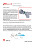
Designed to withstand the demands of the most rigorous flow measurement applications the Model 1100 turbine flow meter
is reliable, rugged and cost effective. Originally developed for the secondary oil recovery market, the Model 1100 is an ideal
meter for liquid flow measurement on or off the oil field.
The meter features a rugged 316 stainless steel housing and rotor support assemblies, CD4MCU stainless steel rotor, and
abrasive-resistant tungsten carbide rotor, shaft, and journal bearings. The Model 1100 maintains measurement accuracy
and mechanical integrity in the corrosive and abrasive fluids commonly found in oil field water flood project and many
industrial applications.
OPERATING PRINCIPLE
Fluid entering the meter passes through the inlet flow straightener which reduces its turbulent flow pattern and improves
the fluid’s velocity profile. Fluid then passes through the turbine, causing it to rotate at a speed proportional to the fluid
velocity. As each turbine blade passes through the magnetic field, the blade generates an AC voltage pulse in the pickup coil
at the base of the magnetic pickup (see Figure 1). These pulses produce an output frequency proportional to the volumetric
flow through the meter. The output frequency represents flow rate and/or totalization of fluid passing through the turbine
flow meter.
Magnetic Pickup
or
Other Frequency
Output Device
Turbine Rotor
Output
Signal
Figure 1: Schematic illustration of electric signal generated by rotor movement
Magnetic Pick-up
* Rotor and
Rotor Shaft
Conduit Adaptor
* Upstream
Rotor Support
Meter Body
* Retaining Ring
Retaining Ring
Groove
Retaining Pins
* Downstream
Rotor Support
* Thrust Ball
* Bearing
NOTE: * Indicates parts supplied in repair kits.
Figure 2: Typical cross-section of B110-375…B111-121 turbine flow meter
July 2014
TUR-UM-00014-EN-03
Page 3