1
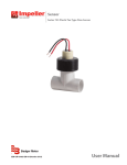
Recordall® Industrial Meters
Nutating Disc Meter
RDM-UM-01089-EN-06 (September 2014)
User Manual
Recordall® Industrial Meters, Nutating Disc Meter
CONTENTS
Description . . . . . . . . . . . . . . . . . . . . . . . . . . . . . . . . . . . . . . . . . . . . . . . . . . . . . . . . . . . . . . . . . . . . . . . . .3
Operating Principle . . . . . . . . . . . . . . . . . . . . . . . . . . . . . . . . . . . . . . . . . . . . . . . . . . . . . . . . . . . . . . . . . .3
Unpacking and Inspection . . . . . . . . . . . . . . . . . . . . . . . . . . . . . . . . . . . . . . . . . . . . . . . . . . . . . . . . . . . . . . . 4
Installation . . . . . . . . . . . . . . . . . . . . . . . . . . . . . . . . . . . . . . . . . . . . . . . . . . . . . . . . . . . . . . . . . . . . . . . . . 4
General Operating Instructions . . . . . . . . . . . . . . . . . . . . . . . . . . . . . . . . . . . . . . . . . . . . . . . . . . . . . . . . . . . . 5
Manual Operation . . . . . . . . . . . . . . . . . . . . . . . . . . . . . . . . . . . . . . . . . . . . . . . . . . . . . . . . . . . . . . . . . . .5
Accessory Controlled Operation . . . . . . . . . . . . . . . . . . . . . . . . . . . . . . . . . . . . . . . . . . . . . . . . . . . . . . . . . .5
Shutdown Instructions . . . . . . . . . . . . . . . . . . . . . . . . . . . . . . . . . . . . . . . . . . . . . . . . . . . . . . . . . . . . . . . .5
Maintenance . . . . . . . . . . . . . . . . . . . . . . . . . . . . . . . . . . . . . . . . . . . . . . . . . . . . . . . . . . . . . . . . . . . . . . . .6
Preventive Maintenance . . . . . . . . . . . . . . . . . . . . . . . . . . . . . . . . . . . . . . . . . . . . . . . . . . . . . . . . . . . . . . .6
Calibration Check and Adjustment . . . . . . . . . . . . . . . . . . . . . . . . . . . . . . . . . . . . . . . . . . . . . . . . . . . . . . . .6
Servicing . . . . . . . . . . . . . . . . . . . . . . . . . . . . . . . . . . . . . . . . . . . . . . . . . . . . . . . . . . . . . . . . . . . . . . . . .8
Page 2
RDM-UM-01089-EN-06
September 2014
Description
DESCRIPTION
The Badger Meter Recordall (RCDL) positive displacement meters are one of the most cost effective methods in metering
industrial fluids. The RCDL meter has a simple, efficient design for high accuracy and repeatability over the entire meter
flow range.
Available in five sizes, 1/2" through 2" for flows up to 170 gpm, these meters are extremely rugged and reliable. Maintenance
is seldom required, but if necessary, takes only a few minutes. All parts are designed and built of materials that meet your
application requirements and provide an enduring and a trouble-free, precision flow meter.
To complement the RCDL meter line, Badger Meter offers a complete line of accessories that includes totalizers,
electromechanical and electronic endpoints, rate of flow indicators and batch/process controllers.
Operating Principle
The metering principle, known as positive displacement, is based on the continuous filling and discharging of the measuring
chamber. Controlled clearances between the disc and the chamber provide precise measurement of each volume cycle.
As the disc nutates, the center spindle rotates a magnet. The movement of the magnet is sensed through the meter wall
by a follower magnet or by various sensors. Each revolution of the magnet is equivalent to a fixed volume of fluid, which is
converted to any engineering unit of measure for totalization, indication or process control.
Liquid flowing through the meter chamber (A) causes a disc (B) to nutate or wobble. This motion, in turn, results in the
rotation of a spindle (C) and drive magnet (D). Rotation is transmitted through the wall of the meter to a second magnet (E) or
varied style of sensor pickup.
E
C
D
B
A
Figure 1: Nutating disc operation
September 2014
RDM-UM-01089-EN-06
Page 3
Unpacking and Inspection
UNPACKING AND INSPECTION
Upon receipt of meter, perform the following:
NNOTE: If damage to the shipping container is evident, request the carrier to be present when meter is unpacked.
1. Carefully open the shipping container. Remove all the cushioning material surrounding the meter and carefully lift the
meter from the container. Retain all of the packing material for possible use in reshipment or storage of the meter.
2. Visually inspect the meter and the accessory device for any physical damage such as scratches, loose or broken parts, or
any other damage that may have occurred during shipment of the product.
NNOTE: If damage is found upon receipt of the equipment, request inspection by the carrier's agent within 48 hours of
the delivery. Then file a claim with the carrier. A claim for the equipment damaged in transit is the responsibility of
the customer.
INSTALLATION
IIMPORTAN
The meter must be installed horizontally in the line with the registration upright.
Any special instructions required for the installation and or electrical connection of any meter-mounted or freestanding
accessory devices, such as registers, pulse transmitters, and remote batch controllers, will be provided as a supplement to
this manual.
Please read the following instructions to become familiar with the requirements and the recommended procedures involved.
THE METER MUST BE OPERATED IN AN APPLICATION WITHIN THE SPECIFIED TEMPERATURE RANGE TO OBTAIN
OPTIMUM ACCURACY AND PREVENT DAMAGE TO ANY INTERNAL COMPONENTS.
1. Verify the fluid operating temperature range is compatible with the materials of construction of the meter received.
THE LIFE OF THE METER WILL BE IMPAIRED IF IT IS OPERATED AT FLOW RATES IN EXCESS OF THOSE INDICATED IN THE
PRODUCT SPECIFICATIONS.
2. If any solid material is present in the liquid, install a strainer upstream of the meter.
3. Locate the meter installation with consideration for sufficient space for cleaning and maintenance of the meter.
4. Review the overall dimensions (including laying length requirements) of the meter. If necessary, consider the height
dimensions including the meter-mounted accessory. Then proceed as follows:
a. Measure the overall length of the meter with the connection pieces attached to the inlet and outlet spuds of the meter.
b. Be sure to provide this proper gap length in the facility piping.
Page 4
RDM-UM-01089-EN-06
September 2014
General Operating Instructions
EXCESS GAP LENGTH MAY CAUSE EXCESSIVE STRAIN ON CONNECTION ASSEMBLIES.
c. Remove the connections and install one connection piece in each end of the facility pipe gap provided in step 4b.
Allow for the gaskets at the inlet and the outlet spuds of the meter.
d. Install the meter, making sure that the flow arrow marking on the meter housing is in the correct relationship to the
direction of the fluid flow in the system.
e. Tighten the meter connections. Note the instructions on packaging from connection assembly when tightening.
f. To relieve any possible strain on the facility piping that might be caused by the weight of any of the large size meters,
consider incorporating a meter support under the housing of the meter.
To ensure that the meter has been properly installed and is operational:
1. Slowly open the upstream valve to apply fluid pressure to the meter. Check the connections for any possible leakage.
Retighten the connections as required.
2. Perform a functional test of the meter following "Calibration Check and Adjustment" on page 6.
GENERAL OPERATING INSTRUCTIONS
In general, the operation of a Model RCDL disc meter is either manually controlled or accessory controlled. Manual operation
applies to the applications employing hand-operated valves or other manually activated, flow-regulating devices that are not
functionally controlled by a meter accessory. Accessory controlled operation applies to applications when a meter accessory
provides a signal output to activate and/or deactivate a valve or other flow control device.
VALVES CONTROLLING THE FLUID FLOW THROUGH THE METER SHOULD BE OPENED AND CLOSED SLOWLY TO
PREVENT SHOCK LOADS THAT MAY DAMAGE THE METER MEASURING ELEMENT.
Manual Operation
The following procedures are for use in simple metering applications where the flow of fluid is controlled by hand-operated
valves located upstream and downstream of the meter.
1. Slowly open the upstream valve to apply fluid to the meter.
2. Slowly open the downstream valve to initiate the metering operation.
3. Adjust the downstream valve so the flow rate of the fluid does not exceed the maximum continuous flow rate specification
of the meter.
NNOTE: On meters with an accessory device providing a totalizing indicator, the flow rate of the fluid can be checked by
timing the number of gallons registered in one minute.
4. To stop metering, slowly close the downstream valve; then close the upstream valve.
Accessory Controlled Operation
Operating procedures for accessory controlled applications are dependent on the specific function of that accessory
employed and its electrical interconnection with a flow control device or devices. Refer to the bulletin or bulletins covering
the applicable accessories for specific operating instructions (included as a supplement to this manual when required.)
Shutdown Instructions
If the meter is to be shut down for an extended period of time, first flush out the measuring chamber of the meter to prevent
the settling out of undissolved solids or the accumulation of corrosive deposits.
September 2014
RDM-UM-01089-EN-06
Page 5
Maintenance
MAINTENANCE
Preventive Maintenance
Preventive maintenance consists of periodic inspection and cleaning procedures. Perform the procedures at regular intervals
and correct any defects before resuming operation of the meter.
Periodic Inspection
1. Visually inspect the meter and teh accessory for missing hardware, loose connections, broken register glass, damaged
wiring, or other signs of wear or deterioration. Repair or replace components as required.
2. Verify the proper flow rate and pressure for meter. A loss in pressure, with the resulting flow rate decrease, may indicate
the meter screen is clogged and requires cleaning.
Cleaning
Clean all dust, dirt, grease, moisture, or other foreign material from the exterior of the meter and the accessory.
Calibration Check and Adjustment
Follow these instructions to perform on-site calibration checks and adjustments.
Accuracy Test
1.
2.
3.
4.
5.
Place a test tank of known volume at the output of the meter.
Fill the test tank to the calibrated level. Make a test run at the same flow rate to be used in the actual operation.
Record the quantity indicated on the accessory.
Repeat the test three times and average the recorded results.
Perform the following calculations to determine the percent of accuracy of the meter-accessory combination.
Qty. Indicated on Accessory
Actual Quantity in Test Tank
x 100 = Meter Accuracy
Example 1.
95 Gallons
x 100 = 95% Accuracy
100 Gallons
In this example, the meter-mounted accessory is slow and the reading is low. A calibration adjustment is required to
speed up the accessory.
Example 2.
104 Gallons
x 100 = 104% Accuracy
100 Gallons
In this example, the meter-mounted accessory is fast and running high. A calibration adjustment is required to slow
down the accessory.
Page 6
RDM-UM-01089-EN-06
September 2014
Maintenance
Change-Gear Calibration
If the accuracy test of a meter-accessory combination indicates that an adjustment is required and change-gears are the
medium for calibration, proceed as follows:
1. Remove applicable Driver (Accessory) change-gear and Driven (Meter) change-gear.
NNOTE: The number of teeth and outside diameter is stamped on each gear.
Accessory
Device
Accessory (Driven)
Change Gear
Meter (Driver)
Change Gear
Magnetic Gear
Train
Figure 2: Change-gear locations on model RCDL meters
2. Calculate the ratio of the existing change-gears as follows:
Ratio =
No. of Teeth on Accessory Change-gear
No. of Teeth on Meter Change-gear
3. Calculate the new change-gear ratio required by multiplying the ratio of existing change-gears by the percent of the
meter accuracy determined in the accuracy test.
Example
Existing Change-gear Ratio =
42 Teeth
= 0.976
43 Teeth
Meter Accuracy = 95%
Corrected Change-gear Ratio = 0.976 x
95
100
= 0 .927
4. If change-gear charts are available, select a new change-gear combination that matches the corrected change-gear ratio.
If new gears are not available, submit an order for corrective change-gears to the nearest Badger Meter Representative or
contact the Industrial Division of Badger Meter, Inc.
NNOTE: When ordering, specify the serial number of meter, the meter model and size, the accessory device employed, the
number of teeth and diameter of existing change-gears, and the corrected change-gear ratio required.
5. Observe the position of the old change-gears on the spindles before removing them. Install the new change-gears on the
meter and accessory spindles and assemble the accessory to meter. Make sure you obtain full mesh when assembling the
accessory to the meter gear train adapter. Note the position information from the old gears.
September 2014
RDM-UM-01089-EN-06
Page 7
Electronic Calibration
If electronic scaling is the accessory medium for calibration, see the accessory technical brief for instructions.
Servicing
The following instructions are for removal, inspection and installation of meter parts and assemblies. Refer to applicable
illustrated parts list for part numbers of components and ordering information. Accessory service and repair procedures are
provided in literature specific to that device.
Meter Disassembly Method
These procedures are for disassembly of the meter:
1. Shut off the fluid flow to meter. Place a container under the meter and relieve fluid pressure in the meter by uniformly
loosening the bolts (bronze meter) or the retaining ring (plastic meter). Fluid will run out into the container.
2. Remove the bolts or the retaining ring while holding the housing bottom in place. Remove the housing bottom. The
chamber assembly may drop from the housing as the bottom is removed.
3. If the chamber assembly is out, set it aside. If not, first remove the chamber strap and then remove the chamber assembly.
4. Remove the meter screen. Inspect the screen for dirt and corrosion. Clean or replace the screen as necessary.
5. Inspect the chamber assembly:
a. Check the disc in the chamber assembly for warpage, cracks or wear. A severely worn disc can cause
over-delivery of the fluid being metered.
b. Check the thrust roller and thrust roller insert for excessive wear.
After inspection, clean or replace the chamber assembly as necessary. If the chamber is worn or corroded, replace the entire
chamber and disc assembly.
6. Re-install the housing chamber assembly, screen, chamber strap and bottom as follows:
a. Assemble the screen in the proper location.
b. Position the chamber assembly in the proper orientation. Add the chamber strap.
c. Position the housing bottom with the correct seal. (Replacement of seal is always recommended.)
d. Assemble and tighten the bolts or retaining ring.
Alternative Disassembly Method for Service
Loosen all the connection pieces slightly. Turn the meter upside-down, putting gravity on your side. This will help eliminate
the possibility of the chamber assembly and or the screen component dropping during disassembly and causing damage.
Recalibration
After repairing or replacing a meter component or assembly, perform the calibration check and adjustment procedure to
ensure that the meter is properly calibrated and will operate in accordance with published specifications.
Control. Manage. Optimize.
Trademarks appearing in this document are the property of their respective entities. Due to continuous research, product improvements and enhancements, Badger Meter reserves
the right to change product or system specifications without notice, except to the extent an outstanding contractual obligation exists. © 2014 Badger Meter, Inc. All rights reserved.
www.badgermeter.com
The Americas | Badger Meter | 4545 West Brown Deer Rd | PO Box 245036 | Milwaukee, WI 53224-9536 | 800-876-3837 | 414-355-0400
México | Badger Meter de las Americas, S.A. de C.V. | Pedro Luis Ogazón N°32 | Esq. Angelina N°24 | Colonia Guadalupe Inn | CP 01050 | México, DF | México | +52-55-5662-0882
Europe, Middle East and Africa | Badger Meter Europa GmbH | Nurtinger Str 76 | 72639 Neuffen | Germany | +49-7025-9208-0
Europe, Middle East Branch Office | Badger Meter Europe | PO Box 341442 | Dubai Silicon Oasis, Head Quarter Building, Wing C, Office #C209 | Dubai / UAE | +971-4-371 2503
Czech Republic | Badger Meter Czech Republic s.r.o. | Maříkova 2082/26 | 621 00 Brno, Czech Republic | +420-5-41420411
Slovakia | Badger Meter Slovakia s.r.o. | Racianska 109/B | 831 02 Bratislava, Slovakia | +421-2-44 63 83 01
Asia Pacific | Badger Meter | 80 Marine Parade Rd | 21-06 Parkway Parade | Singapore 449269 | +65-63464836
China | Badger Meter | 7-1202 | 99 Hangzhong Road | Minhang District | Shanghai | China 201101 | +86-21-5763 5412
Legacy Document: IOM-067-05-EN 53400-067