1
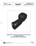
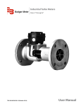
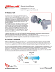
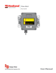
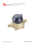
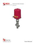
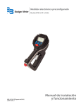
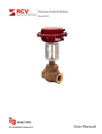
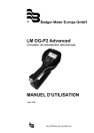
Electronic Preset Meter 2 Advanced Series
Special Fluids Plus
Model EPM2-ADV-SF Plus
AUT-UM-00916-EN-04 (May 2014)
User Manual
Electronic Preset Meter 2, Advanced Series Special Fluids Plus Model EPM2-ADV-SF Plus
Page ii
May 2014
User Manual
CONTENTS
Safety . . . . . . . . . . . . . . . . . . . . . . . . . . . . . . . . . . . . . . . . . . . . . . . . . . . . . . . . . . . . . . . . . . . . . . . . . . . . . 5
Meter Buttons . . . . . . . . . . . . . . . . . . . . . . . . . . . . . . . . . . . . . . . . . . . . . . . . . . . . . . . . . . . . . . . . . . . . . . . .6
LCD Display . . . . . . . . . . . . . . . . . . . . . . . . . . . . . . . . . . . . . . . . . . . . . . . . . . . . . . . . . . . . . . . . . . . . . . . . . .6
Meter Installation . . . . . . . . . . . . . . . . . . . . . . . . . . . . . . . . . . . . . . . . . . . . . . . . . . . . . . . . . . . . . . . . . . . . . .7
Relieve System Pressure . . . . . . . . . . . . . . . . . . . . . . . . . . . . . . . . . . . . . . . . . . . . . . . . . . . . . . . . . . . . . . .7
Grounding . . . . . . . . . . . . . . . . . . . . . . . . . . . . . . . . . . . . . . . . . . . . . . . . . . . . . . . . . . . . . . . . . . . . . . . 7
Flushing Procedure . . . . . . . . . . . . . . . . . . . . . . . . . . . . . . . . . . . . . . . . . . . . . . . . . . . . . . . . . . . . . . . . . .7
Attach Meter to Hose . . . . . . . . . . . . . . . . . . . . . . . . . . . . . . . . . . . . . . . . . . . . . . . . . . . . . . . . . . . . . . . . .8
Attach Nozzle to Meter . . . . . . . . . . . . . . . . . . . . . . . . . . . . . . . . . . . . . . . . . . . . . . . . . . . . . . . . . . . . . . . .8
Meter Operation . . . . . . . . . . . . . . . . . . . . . . . . . . . . . . . . . . . . . . . . . . . . . . . . . . . . . . . . . . . . . . . . . . . . . . .9
Manual Mode . . . . . . . . . . . . . . . . . . . . . . . . . . . . . . . . . . . . . . . . . . . . . . . . . . . . . . . . . . . . . . . . . . . . . .9
Auto Batch Mode . . . . . . . . . . . . . . . . . . . . . . . . . . . . . . . . . . . . . . . . . . . . . . . . . . . . . . . . . . . . . . . . . . . 9
Count up and Count Down Modes . . . . . . . . . . . . . . . . . . . . . . . . . . . . . . . . . . . . . . . . . . . . . . . . . . . . . . . 10
Operating Mode Functions . . . . . . . . . . . . . . . . . . . . . . . . . . . . . . . . . . . . . . . . . . . . . . . . . . . . . . . . . . . . . . . 11
Re-settable and Accumulated Totals . . . . . . . . . . . . . . . . . . . . . . . . . . . . . . . . . . . . . . . . . . . . . . . . . . . . . . 11
Emergency Override . . . . . . . . . . . . . . . . . . . . . . . . . . . . . . . . . . . . . . . . . . . . . . . . . . . . . . . . . . . . . . . . 12
History . . . . . . . . . . . . . . . . . . . . . . . . . . . . . . . . . . . . . . . . . . . . . . . . . . . . . . . . . . . . . . . . . . . . . . . . . 12
Flow Rate . . . . . . . . . . . . . . . . . . . . . . . . . . . . . . . . . . . . . . . . . . . . . . . . . . . . . . . . . . . . . . . . . . . . . . . 12
Error Codes . . . . . . . . . . . . . . . . . . . . . . . . . . . . . . . . . . . . . . . . . . . . . . . . . . . . . . . . . . . . . . . . . . . . . . 12
Service . . . . . . . . . . . . . . . . . . . . . . . . . . . . . . . . . . . . . . . . . . . . . . . . . . . . . . . . . . . . . . . . . . . . . . . . . . . . 12
Low Battery . . . . . . . . . . . . . . . . . . . . . . . . . . . . . . . . . . . . . . . . . . . . . . . . . . . . . . . . . . . . . . . . . . . . . . 12
Changing the Batteries . . . . . . . . . . . . . . . . . . . . . . . . . . . . . . . . . . . . . . . . . . . . . . . . . . . . . . . . . . . . . . . 13
Change Factory Settings . . . . . . . . . . . . . . . . . . . . . . . . . . . . . . . . . . . . . . . . . . . . . . . . . . . . . . . . . . . . . . . . 13
Verify Firmware Version . . . . . . . . . . . . . . . . . . . . . . . . . . . . . . . . . . . . . . . . . . . . . . . . . . . . . . . . . . . . . . 13
Programming . . . . . . . . . . . . . . . . . . . . . . . . . . . . . . . . . . . . . . . . . . . . . . . . . . . . . . . . . . . . . . . . . . . . . 13
Change Unit of Measure . . . . . . . . . . . . . . . . . . . . . . . . . . . . . . . . . . . . . . . . . . . . . . . . . . . . . . . . . . . . . . 14
Change Scale Factor . . . . . . . . . . . . . . . . . . . . . . . . . . . . . . . . . . . . . . . . . . . . . . . . . . . . . . . . . . . . . . . . 14
Save Changes . . . . . . . . . . . . . . . . . . . . . . . . . . . . . . . . . . . . . . . . . . . . . . . . . . . . . . . . . . . . . . . . . . . . 15
Verify Changes . . . . . . . . . . . . . . . . . . . . . . . . . . . . . . . . . . . . . . . . . . . . . . . . . . . . . . . . . . . . . . . . . . . . 15
Calculate Scale Factor . . . . . . . . . . . . . . . . . . . . . . . . . . . . . . . . . . . . . . . . . . . . . . . . . . . . . . . . . . . . . . . . . . 15
Absolute Scale Factor . . . . . . . . . . . . . . . . . . . . . . . . . . . . . . . . . . . . . . . . . . . . . . . . . . . . . . . . . . . . . . . . 15
Chart of Approximate Scale Factors . . . . . . . . . . . . . . . . . . . . . . . . . . . . . . . . . . . . . . . . . . . . . . . . . . . . . . . 16
Dimensions . . . . . . . . . . . . . . . . . . . . . . . . . . . . . . . . . . . . . . . . . . . . . . . . . . . . . . . . . . . . . . . . . . . . . . . . . 16
May 2014
Page iii
Electronic Preset Meter 2, Advanced Series Special Fluids Plus Model EPM2-ADV-SF Plus
Specifications . . . . . . . . . . . . . . . . . . . . . . . . . . . . . . . . . . . . . . . . . . . . . . . . . . . . . . . . . . . . . . . . . . . . . . . 17
Parts . . . . . . . . . . . . . . . . . . . . . . . . . . . . . . . . . . . . . . . . . . . . . . . . . . . . . . . . . . . . . . . . . . . . . . . . . . . . . 17
Troubleshooting . . . . . . . . . . . . . . . . . . . . . . . . . . . . . . . . . . . . . . . . . . . . . . . . . . . . . . . . . . . . . . . . . . . . . . 19
Page iv
May 2014
User Manual
SAFETY
IMPROPER GROUNDING, POOR VENTILATION, OPEN FLAMES OR SPARKS CAN CAUSE A HAZARDOUS CONDITION AND
RESULT IN AN EXPLOSION OR FIRE AND CAUSE SERIOUS INJURY.
• Be sure the fluid system is properly grounded. See your pump instruction manual for details.
• If there is static sparking or if you feel an electric shock while using the meter, stop dispensing immediately. Identify and
correct the problem before continuing.
• Provide fresh air ventilation. This will avoid the buildup of fumes from the fluid being dispensed.
• Do not smoke while dispensing flammable fluids.
• Keep the dispensing area free of debris including solvents, rags and spilled gasoline.
EQUIPMENT MISUSE CAN CAUSE THE METER TO RUPTURE OR MALFUNCTION AND CAUSE SERIOUS INJURY.
• This equipment is for professional use only.
• Read all instructions, tags and labels before operating the equipment.
• Use the equipment only for its intended purpose.
• Do not modify or alter the equipment.
• Do not leave equipment unattended while dispensing.
• Check equipment daily. Repair or replace worn or damaged parts immediately.
• Do not exceed the maximum working pressure level of the lowest rated system component.
• Use only extensions and nozzles that are designed for use with this equipment.
• Use only fluids and solvents that are compatible with the equipment. Read all fluid and solvent manufacturer’s warnings.
• Tighten all fluid connections before operating this equipment.
• Do not stop or deflect leaks with hands, body, gloves or rags.
• Do not dispense towards any person or any part of the body.
• Do not place hands or fingers over the end of or into the dispense valve.
• Comply with all local, state, and federal fire, electrical and safety regulations
• Use of this product in a manner other than specified in this manual may result in impaired operation or
damage to equipment.
THIS METER IS DESIGNED SPECIFICALLY TO DISPENSE ANTIFREEZE (ETHYLENE GLYCOL) SOLUTION, WINDSHIELD
WIPER FLUID, BRAKE FLUID AND WATER BASED SOLUTION. DO NOT USE FOR PETROLEUM PRODUCTS.
May 2014
Page 5
Electronic Preset Meter 2, Advanced Series Special Fluids Plus Model EPM2-ADV-SF Plus
METER BUTTONS
Figure 1: Meter button locations
Used to enter the batch quantity to be dispensed.
Used to display the accumulated total of fluid dispensed as well as the re-settable total during
Auto Batch and Manual Mode.
Used to enter and exit the Manual or Auto Batch mode.
• Used in the Manual mode to clear the dispensed quantity.
• Used in the Auto Batch mode to clear the dispensed quantity and reset the meter for the
next batch.
• Used to reset the re-settable total dispensed while pressing the TOTAL button.
Used to stop the flow through an Emergency Override.
Table 1: Button descriptions
LCD DISPLAY
1. Displays Re-settable Total, Accumulated Total and Scale
Factor.
2
1
2. Displays Unit of Measure.
3. Arrows notify when in Count Up or Count Down.
3
4. Preset batch quantity.
5. History icon.
6. Auto is an indicator of unit being in Auto Batch Mode.
7
6
5
4
7. Low battery icon.
Table 2: LCD display description
Page 6
May 2014
User Manual
METER INSTALLATION
Relieve System Pressure
THIS EQUIPMENT STAYS PRESSURIZED UNTIL THE PRESSURE IS MANUALLY RELIEVED.
1. Turn off the power supply to the pump or close the shutoff valve.
2. Dispense any fluid in the system into a waste container by opening the meter.
3. Open all bleed-type master air valves and fluid meter in the system.
4. Leave the meter open until ready to pressurize the system.
To reduce the risk of injury from fluid spray from the meter, follow this procedure when you:
• Are instructed to relieve pressure.
• Stop dispensing.
• Check, clean or service any system equipment.
• Clean or install nozzles.
Grounding
MOVEMENT OF FLUIDS THROUGH THE DISPENSING SYSTEM CREATES STATIC ELECTRICITY. STATIC ELECTRICITY CAN
CAUSE VOLATILE FUMES RESULTING IN AN EXPLOSION AND FIRE. THE DISPENSING SYSTEM MUST BE GROUNDED.
Grounding reduces the risk of static sparking. Ground all system components according to local, state and federal codes.
Consult the pump user manual and other system components to ground the following:
1. Pump: follow manufacturer's recommendations
2. Air and Fluid Hoses: use only grounded hoses
3. Air Compressor: follow manufacturers recommendations
4. Fluid Supply Container: follow the local code
Flushing Procedure
IF THIS INSTALLATION IS NEW OR IF THE FLUID IN THE LINES IS CONTAMINATED, FLUSH THE SYSTEM BEFORE
INSTALLING THE METER(S).
NNOTE: If the system has multiple dispense positions, begin at the position farthest from the pump and move towards
the pump.
1. Close fluid dispense valves at every position.
2. Once the main fluid outlet valve at the pump is closed and the air pressure to the pump motor is properly adjusted, the air
valve is opened.
3. Slowly open the main fluid valve.
4. Place the hose end in a waste container. Make sure the hose is secure so no fluid leaks during flushing.
5. Slowly open the dispense valve and allow enough fluid to pass through it to ensure that the system is clean.
6. Close the valve and repeat for all dispense positions.
May 2014
Page 7
Electronic Preset Meter 2, Advanced Series Special Fluids Plus Model EPM2-ADV-SF Plus
Attach Meter to Hose
Close the drain valve before starting this procedure.
1. Attach swivel to meter. Apply thread sealant to the male end of the hose. Recommended sealant is Loctite® 243.
See Figure 2.
Figure 2: Apply thread sealan
2. Insert the metal end of the hose into the swivel. See Figure 3.
Figure 3: Insert hose into swivel
3. Tighten completely with an open ended, adjustable, wrench. See Figure 4.
Figure 4: Use wrench to tighten
NNOTE: The threaded end of the meter always has female threads. The metal end of the hose must have male threads. The
inlet and outlet swivel connections are either 1/2" NPT or 1/2" BSPP, depending on meter model.
Attach Nozzle to Meter
1. On the opposite end, apply sealant to the end of the nozzle. Recommended sealant is Loctite® 243.
2. Thread the nozzle onto the meter. See Figure 5.
Figure 5: Thread nozzle onto meter
3. Screw it in tightly with an open-ended, adjustable, wrench. See Figure 6.
Page 8
May 2014
User Manual
Figure 6: Tighten nozzle with wrench
4. Open all dispense position shut-off valves. Start the pump to pressurize the system.
5. Before use, to ensure accuracy, purge all air from the fluid lines and dispense valve(s).
METER OPERATION
NNOTE: The keypad Auto button is used to toggle between Manual Mode and Auto Batch Mode.
Manual Mode
In Manual Mode the meter operates as a free flow-dispensing handle.
Figure 7: Manual mode screen
1.
2.
3.
4.
Pull the trigger to begin the flow.
The display shows the amount dispensed.
When the desired amount has been dispensed, release the trigger to stop the flow.
Press
once to reset the counter display to zero.
Auto Batch Mode
To enter Auto Batch Programming Mode, press
until a digit and colon appears.
Figure 8: Auto batch mode screen
The meter is now ready to select the desired batch number.
• The ‘0’ is flashing in front of the colon. This is the batch number icon.
• Batch ‘0’ is for Manual Mode. See "Manual Mode".
• Batches ‘1’ through ‘5’ are for auto batching amounts up to 99 units.
• Different batch amounts can be stored in each option.
• Batch ‘6’ is for batches between 1 and 999 units.
1. Press
to cycle through the batch number icons to select the desired batch or manual mode.
2. After selecting the correct batch number, change the batch size by pressing
,
and
May 2014
.
Page 9
Electronic Preset Meter 2, Advanced Series Special Fluids Plus Model EPM2-ADV-SF Plus
Figure 9: Auto batch mode option 1
To batch in options 1...5:
• Press
to increase a batch by 10 units.
• Press
to increase a batch by 1 unit.
• Press
to increase a batch by 0.1 of a unit.
Figure 10: Auto batch mode option 6
To batch in option 6:
• Press
to increase a batch amount in increments of 100 units.
• Press
to increase a batch amount in increments of 10 units.
• Press
to increase a batch amount in increments of 1 unit.
3. After the batch size is selected, press
to lock in the batch and dispense fluid.
Auto Batch
Size
Auto Icon
Figure 11: Auto batch mode display
4. Pull the trigger to begin the flow. The solenoid valve, in the meter, automatically locks the dispensing valve in the full
open position.
THE METER ALWAYS LOCKS IN THE MAXIMUM OPEN POSITION.
5. Release the trigger, allowing it to fall back.
6. The flow automatically shuts off after the batch quantity has dispensed.
7. After the batch quantity has been dispensed the meter is a free flow-dispensing handle until the reset button is depressed.
NNOTE: In case of an emergency or to interrupt a batch, the meter is equipped with an Emergency Override. See "Emergency
Override" on page 12.
8. The user has the option to top off the fluid at the end of a batch. To top off the fluid, pull the trigger to begin the flow and
release it when the desired amount has been pumped.
9. Press
when finished. The display resets and the meter is now ready to dispense the next batch.
Count up and Count Down Modes
In Count Up Mode the meter counts up to the pre-programmed batch amount. In Count Down Mode the meter counts from
the programmed batch amount down to zero.
Page 10
May 2014
User Manual
NNOTE: Batch number 3 is always in Count Down Mode.
1. When in the Auto Batch Programming Mode, press
and the count up/count down arrows flash in the display.
Figure 12: Display for count up and count down modes
• Press
to toggle between Count Up and Count Down.
• Press
to select Count Up or Count Down.
2. Press
to lock in the batch quantity when batch size is selected. The screen will flash and the batch number icon will
not appear on the display.
Figure 13: Batch quantity size in count up and count down modes
• If the meter is in Count Up Mode, the display shows zeroes.
• If the meter is in the Count Down Mode, the selected batch size is displayed.
OPERATING MODE FUNCTIONS
These functions operate the same in Manual Mode and Auto Batch Mode.
Re-settable and Accumulated Totals
The meter has two flow totalizers, Re-settable Total and Accumulated Total.
1. Press and hold
to display Accumulated Total, after holding for three seconds the display changes to
Re-settable Total.
2. Resettotal displays the total fluid dispensed since the Re-settable Total was last set back to zero.
Figure 14: Re-settable total display
3. Press
while viewing Resettotal to set it back to zero.
4. Release
to return to the operating screen.
NNOTE: The Accumulated Total cannot be reset unless the user changes from English units to metric units or from metric to
English units. See "Change Unit of Measure" on page 14.
May 2014
Page 11
Electronic Preset Meter 2, Advanced Series Special Fluids Plus Model EPM2-ADV-SF Plus
Emergency Override
In case of an emergency or to interrupt a batch, the meter is equipped with an Emergency Override which closes the valve,
immediately stopping fluid flow.
1. Press
to activate the Emergency Override.
2. After an Emergency Override, batching can continue by pulling up on the trigger.
History
This option allows the user to review the previous five batches dispensed with the meter.
Figure 15: History display
1. Press and hold
to view he five previous batches.
a. The batches are displayed on screen, one at a time; beginning with the most recent and cycling through to the oldest.
The batches will continue to cycle until the button is released.
2. The display automatically returns to the normal operating screen two seconds after the button is released.
NNOTE: The history cannot be erased unless the user changes from English to metric or from metric to English units. See
"Change Unit of Measure" on page 14.
Flow Rate
This option allows a user to see instantaneously the rate at which fluid is flowing through the meter.
Figure 16: Flow rate display
Press and hold
while fluid is flowing through the meter. The Flow Rate will appear in the bottom right hand corner of
the display. The Flow Rate will remain on the screen until the button is released. Releasing the button returns the display to
the normal operating screen.
NNOTE: The Flow Rate can only be displayed if fluid is flowing through the meter.
Error Codes
The meter has one error code that may display:
SF0 (Scale Factor 0) The Scale Factor setting for the meter is set to 0.000.
The code provides an indication, at the meter, that there is an error in communication between the meter and keypad. To
correct the error, input a valid Scale Factor for the meter follow the instructions in "Change Factory Settings" on page 13. All
other error codes are for factory purposes only. To clear the meter, press
.
SERVICE
Low Battery
When the batteries need to be changed a progression of warnings appears on the meter screen. First, the Low Battery icon will
appear on the display, this means that the batteries are getting low, and should be changed. When the icon begins to flash,
the battery power is too low, and meter functions are disabled.
Page 12
May 2014
User Manual
Low Battery
Icon
Figure 17: Low battery icon
Changing the Batteries
The battery compartment is located in the lower case on the underside of the trigger guard.
1. Turn the unit over.
2. Unscrew the two screws. Remove the battery door to expose the batteries.
Figure 18: Replacing the batteries
3. Replace the old batteries. The meter takes four AA, alkaline, batteries.
4. Dispose of used batteries properly, according to local regulations.
NNOTE: Changing the batteries does not affect any of the programmed values or totals.
CHANGE FACTORY SETTINGS
Each meter is calibrated at the factory for use with motor oil. See "Change Scale Factor" on page 14. The Unit of Measure is
also selected prior to shipment.
Verify Firmware Version
The firmware version and code checksum are displayed by pressing and holding
and
simultaneously. The last
two digits on the lower right are the firmware version. Meters with version 17 or higher use the procedure outlined in this
manual for changing the unit of measure, scale factor and enabling or disabling the EPM functionality.
Programming
1. Press and hold
and
simultaneously. PrG will appear on the display.
Figure 19: Entering programming mode
May 2014
Page 13
Electronic Preset Meter 2, Advanced Series Special Fluids Plus Model EPM2-ADV-SF Plus
2. Release the buttons.
3. Press and release these buttons in order:
,
,
,
, and
.
4. The current unit of measure will now be flashing indicating that you have entered the programming mode.
Change Unit of Measure
The meter comes with an option to choose four different units of measure.
Scale Factor
Digits
Unit of Measure
Figure 20: Unit of measure display
The current unit of measure will flash when Programming Mode is entered.
Press
to toggle amongst the four options; PT, QT, GAL, L.
When the correct unit of measure is displayed, press
to select it. The unit of measure will stop flashing.
If L (liters) is selected, the decimal point will being to flash. The decimal point can either be changed to a comma or a
period. To do this press
.
5. If no scale factor changes are necessary, see "Save Changes" on page 15.
1.
2.
3.
4.
CHANGING THE UNIT OF MEASUREMENT FROM METRIC TO ENGLISH OR FROM ENGLISH TO METRIC CLEARS THE
RE-SETTABLE TOTAL AND ACCUMULATED TOTAL.
Change Scale Factor
CHANGING THE SCALE FACTOR CHANGES THE ACCURACY OF THE METER, POTENTIALLY CAUSING IT TO OVERFILL OR
UNDER FILL. THIS HAS THE POTENTIAL TO CAUSE A MECHANICAL BREAKDOWN.
Scale factor digits
Figure 21: Scale factor display
1. Press
to advance through the scale factor digits.
2. To change the selected number, press
.
NNOTE: All digits can be scrolled between 0 and 9 except the first. It can only be scrolled from 0 to 1 or from 1 to 0.
3. Press
to advance to the next digit in the scale factor.
4. Repeat steps 2 and 3 for all five digits.
Page 14
May 2014
User Manual
Save Changes
To save changes and exit programming mode:
1. Press and hold
and
simultaneously.
2. The display will flash three times and go blank.
3. Press
and the display will turn back on.
Verify Changes
1. Verify unit of measure is correct.
2. Press and hold
and
simultaneously to verify the scale factor is correct.
CALCULATE SCALE FACTOR
A Scale Factor is a number used to adjust meter accuracy. The Scale Factor is set at the factory using motor oil with a viscosity
of 10W. The primary use for Scale Factor recalibration is to batch fluids with different viscosities. If the fluid has a lower
viscosity, more fluid can slip past the meter gears without being detected. Changing the Scale Factor adjusts the meter to
compensate for the loss. The meter multiplies each pulse by the Scale Factor number to correct the accuracy when it converts
to the specified units. For an approximate Scale Factor for fluids of different viscosities, see "Chart of Approximate Scale Factors"
on page 16.
NNOTE: The meter’s original Scale Factor was written on the trigger when it was calibrated at the factory. It may have been
revised after field installation. Use the Scale Factor showing on the display, not on the trigger.
CHANGING THE SCALE FACTOR WILL CHANGE THE ACCURACY OF THE METER, POTENTIALLY CAUSING IT TO OVERFILL
OR UNDER FILL. THIS HAS THE POTENTIAL TO CAUSE A MECHANICAL BREAKDOWN.
To view the current scale factor press and hold
and
simultaneously.
Absolute Scale Factor
For absolute scale factor, preform this test:
1. Run a measured amount of fluid through the meter.
2. If the meter delivers 4.20 quarts and the display shows only 4.00 quarts, then the Scale Factor needs to be adjusted.
3. Divide what the meter delivered (4.20) by what the display shows (4.00). You get an error factor of (1.05).
4. The existing Scale Factor is 1.0123, as shown in steps 1 and 2 in "Verify Changes" on page 15.
5. To calculate a new factor: 1.0123 (existing Scale Factor) x 1.05 (error factor) = 1.0629 (new Scale Factor).
6. Enter that number as described in the "Change Scale Factor" on page 14.
NNOTE: Use the Scale Factor shown on the display, not on the trigger.
May 2014
Page 15
Electronic Preset Meter 2, Advanced Series Special Fluids Plus Model EPM2-ADV-SF Plus
Chart of Approximate Scale Factors
Figure 22: Scale factors for fluids with different viscosities
Fluid
Viscosity
Scale Factor
Water/anti-freeze
5
1.044
Anti-freeze
18
1.007
Brake Fluid
42
1.004
ATF
80
1.002
10W
140
1.000
80W-90
450
0.999
140W
1800
0.993
Table 3: Fluid viscosity and scale factors
DIMENSIONS
Figure 23: Meter Dimensions
Page 16
May 2014
User Manual
SPECIFICATIONS
Maximum flow *
10 gpm (38 lpm)
Minimum flow *
0.25 gpm (1 lpm)
Operating pressure (maximum)
1000 psi (67 bar)
Operating pressure (minimum)
5 psi (0.35 bar)
Operating temperature (maximum)
120° F (50° C)
Operating temperature (minimum)
20° F (-5° C)
Accuracy (general)
+/- 0.5%
Accuracy (anti-freeze)
+/- 1.5%
5-digit LCD display
Quarts, Pints, Gallons, Liters
Inlet and outlet connections
1/2" NPT (1/2" BSPP)
* Minimum and maximum flow range will vary with fluid viscosity
Table 4: Meter specifications
PARTS
Figure 24: Parts: back of meter
Item
Description
Part Number
1
Battery holder assembly
64103-026
2
Bottom case with screws
64103-003
Table 5: Part numbers: back of meter
May 2014
Page 17
Electronic Preset Meter 2, Advanced Series Special Fluids Plus Model EPM2-ADV-SF Plus
1
2
Figure 25: Parts: front of meter
Item
Description
Part Number
1
Display assembly
64103-023
2
EPM2 adv. register assembly
64103-025
Not shown
Swivel, NPT, special fluids
64082-003
Rubber boot
65546-001
Not shown
Table 6: Part numbers: front of meter
2
1
3
Figure 26: Parts: inside meter
Item
Description
Part Number
1
Valve assembly
64103-011
2
Gear service kit with O-ring
62896-003
3
Trigger Assembly
64103-005
Table 7: Part numbers: inside meter
Page 18
May 2014
User Manual
TROUBLESHOOTING
RELIEVE THE PRESSURE PRIOR TO CHECKING OR REPAIRING THE METER. MAKE SURE ALL VALVES, CONTROLS AND
PUMPS ARE OPERATING CORRECTLY.
Symptom
Possible Cause
Remedy
Battery icon is displayed
Batteries are low
Replace batteries
Display blank
Meter asleep
Loose battery connection
Batteries dead
Meter does not latch for batching
Meter not in AUTO mode
Meter not reset after prior batch
Slow or no fluid flow
Press
Remove battery pack and check battery
connection / press
Replace batteries / press
Press
and program batch size
Press
Low batteries
Check for battery icon / replace batteries /
press
Filter is clogged
Clean or replace the filter in the swivel nut
Pump pressure is low
Turn up the pump pressure
Foreign material is jamming meter
Contact your local distributor for repair
Meter inaccurate
Scale factor not correct for fluid
Enter program mode, check and reset
program factor
Batch overruns program value
Pulse delay value set too low
Enter program mode, reset pulse delay to
a higher value
May 2014
Page 19
Control. Manage. Optimize.
Trademarks appearing in this document are the property of their respective entities. Due to continuous research, product improvements and enhancements, Badger Meter reserves
the right to change product or system specifications without notice, except to the extent an outstanding contractual obligation exists. © 2014 Badger Meter, Inc. All rights reserved.
www.badgermeter.com
The Americas | Badger Meter | 4545 West Brown Deer Rd | PO Box 245036 | Milwaukee, WI 53224-9536 | 800-876-3837 | 414-355-0400
México | Badger Meter de las Americas, S.A. de C.V. | Pedro Luis Ogazón N°32 | Esq. Angelina N°24 | Colonia Guadalupe Inn | CP 01050 | México, DF | México | +52-55-5662-0882
Europe, Middle East and Africa | Badger Meter Europa GmbH | Nurtinger Str 76 | 72639 Neuffen | Germany | +49-7025-9208-0
Europe, Middle East Branch Office | Badger Meter Europe | PO Box 341442 | Dubai Silicon Oasis, Head Quarter Building, Wing C, Office #C209 | Dubai / UAE | +971-4-371 2503
Czech Republic | Badger Meter Czech Republic s.r.o. | Maříkova 2082/26 | 621 00 Brno, Czech Republic | +420-5-41420411
Slovakia | Badger Meter Slovakia s.r.o. | Racianska 109/B | 831 02 Bratislava, Slovakia | +421-2-44 63 83 01
Asia Pacific | Badger Meter | 80 Marine Parade Rd | 21-04 Parkway Parade | Singapore 449269 | +65-63464836
China | Badger Meter | 7-1202 | 99 Hangzhong Road | Minhang District | Shanghai | China 201101 | +86-21-5763 5412
Legacy Document Number: IOM-173-03-EN 53400-173