1
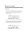
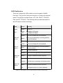
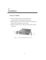
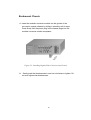
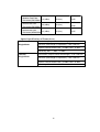
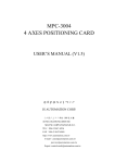
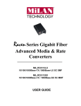
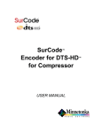
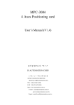
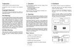
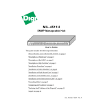
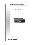
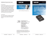
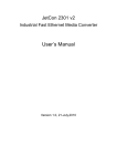
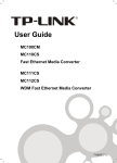
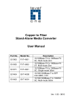
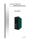
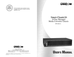
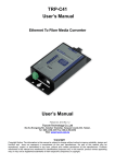
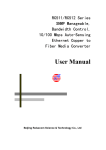
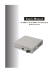
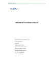
Raven Series Standalone
Media Converters
MIL-RC3112 - 10/100BASE-TX / 100BASE-FX ST MMF
MIL-RC3113 - 10/100BASE-TX / 100BASE-FX SC MMF
MIL-RC3113-XX - 10/100BASE-TX / 100BASE-FX SC SMF
MIL-RC31W13 - 10/100BASE-TX / 100BASE-FX SC SMF TX 1310nm WDM
MIL-RC31W15 - 10/100BASE-TX / 100BASE-FX SC SMF TX 1550nm WDM
USER GUIDE
Regulatory Approval
- FCC Class A
- UL 1950
- CSA C22.2 No. 950
- EN60950
- CE
- EN55022 Class A
- EN55024
Canadian EMI Notice
This Class A digital apparatus meets all the requirements of the Canadian Interference-Causing Equipment Regulations.
Cet appareil numerique de la classe A respecte toutes les exigences du Reglement sur le materiel brouilleur du Canada.
European Notice
Products with the CE Marking comply with both the EMC Directive (89/336/EEC) and the Low Voltage Directive
(73/23/EEC) issued by the Commission of the European Community Compliance with these directives imply conformity to
the following European Norms:
- EN55022 (CISPR 22) - Radio Frequency Interference
- EN61000-X - Electromagnetic Immunity
- EN60950 (IEC950) - Product Safety
One-Year Limited Warranty
Transition Networks warrants to the original consumer or purchaser that each of it's products,
and all components thereof, will be free from defects in material and/or workmanship for a
period of one years from the original factory shipment date. Any warranty hereunder is
extended to the original consumer or purchaser and is not assignable.
Transition Networks makes no express or implied warranties including, but not limited to, any
implied warranty of merchantability or fitness for a particular purpose, except as expressly set
forth in this warranty. In no event shall Transition Networks be liable for incidental or consequential
damages, costs, or expenses arising out of or in connection with the performance of the product
delivered hereunder Transition Networks will in no case cover damages arising out of the product
being used in a negligent fashion or manner.
Trademarks
The MiLAN logo and Transition Networks trademarks are registered trademarks of Transition Networks in the
United States and/or other countries.
To Contact Transition Networks
For prompt response when calling for service information, have the following information ready:
- Product serial number and revision
- Date of purchase
- Vendor or place of purchase
You can reach Transition Networks technical support at:
E-mail: [email protected]
Transition Networks
10900 Red Circle Drive
Minnetonka, MN 55344
United States of America
Telephone: +1.800.526.9267
Fax: : +1.952.941.2322
http://www.milan.com
info@ Transition.com
© Copyright 2006
Transition Networks
FCC Warning
This Equipment has been tested and found to comply with the limits for a Class A digital device, pursuant to Part 15 of
the FCC rules. These limits are designed to provide reasonable protection against harmful interference in a residential
installation.
This equipment generates uses and can radiate radio frequency energy and, if not installed and used in
accordance with the instructions, may cause harmful interference to radio communications. However,
guarantee
that
interference
will
not
occur in
there
is
no
a particular installation. If this equipment does cause harmful
interference to radio or television reception, which can be determined by turning the equipment off and on, the user is
encouraged to try to correct the interference by one or more of the following measures:
Reorient or relocate the receiving antenna.
Increase the separation between the equipment and receiver.
Connect the equipment into an outlet on a circuit different from that to which the receiver is connected.
Consult the dealer or an experienced radio/TV technician for help.
CE Mark Warning
This is a class A product. In a domestic environment this product may cause radio interference in which case
the user may be required to take adequate measures.
Table of Contents
1. Introduction
Features
Package Contents
2. Hardware Description
Front Panel
Ports
LED Indicators
DIP-Switches
Rear Panel
3. Installation
Converter Module
Rackmount Chassis
Cabling
4. Troubleshooting
5. Optical Fiber Specifications
6. Technical Specifications
1.
Introduction
The Raven Series Fast Fiber Advanced Media & Rate Converters
are standalone units that can be used alone or in a 10-slot rackmount
chassis to connect networks with 10/100Base-TX and 100Base-FX
cabling.
These advanced media & rate converters extend the cabling
distance of 100Base-FX network up to 2 kilometers for multi-mode
fiber or 30 kilometers for single mode fiber.
Figure 1-1. The Raven Series Fast Fiber Media Converter Module
Each converter is available with one SC, ST, multi-mode fiber
connector or SC single-mode fiber connector, plus one Ethernet RJ45 port (Auto MDI/MDIX) for your 100Base-TX copper cable
connection. DIP-switches allow for setting the operation mode
for UTP, Fiber and link loss forwarding function.
The WDM Converter converts signals between 10/100Base-TX and
100Base-FX cabling, and incorporates WDM technology that allows
a grouping of different services on existing optical fibers inside. The
WDM technology makes transmit (TX) and receive (RX) lines onto a
1
single fiber, which reduces half of the cabling cost.
WDM converters must be installed in pairs with one 1310nm
wavelength converter at one end of the single fiber cable and one
1550nm wavelength converter at the other end. The fiber cabling can
extend the connectivity distance up to 20 kilometers.
2
Features
Fast Fiber Converter Modules
Comply with IEEE 802.3, 802.3u, and 802.3x standards.
Convert between UTP cabling and Fiber-optic cabling.
One RJ-45 connector, Auto-MDI/MDIX for UTP port.
Support 10/100 Mbps Auto-negotiation for UTP port.
Fiber cabling connectivity up to 30Km.
Uses store-and-forward switching to separate two collision
domains.
One fiber connector (SC/ SC single-mode fiber/ST/ MT-RJ/VF-45)
for 100Base-FX.
4DIP-switches to set the operation mode and Link Loss-Forwarding function.
LEDs for ach port: 100, Link, Activity, Full, Collision.
LEDs for each unit: Power.
External DC power adapter 9V/0.7A.
Two types of module: Stand-alone and mounted in converter
chassis.
FCC Class A, CE, UL, and CUL Mark certification.
WDM Converter Modules
Comply with IEEE 802.3, 802.3u, and 802.3x standards.
Convert between UTP cabling and Fiber-optic cabling.
WDM (Wavelength Division Multiplexing) supports single fiber
converter, transporting Bi-direction full-duplex signal over a
single fiber simultaneously.
One RJ-45 connector, Auto-MDI/MDIX for UTP port.
Support 10/100 Mbps Auto-negotiation for UTP port.
One Single-SC Style Single-Mode Connector for 100 Base- FX
fiber cable.
3
Fiber cabling connectivity up to 60Km.
Uses store-and-forward switching to separate two collision
domains.
4DIP-switches to set the operation mode and Link Loss-Forwarding function.
LEDs for each port: 100, Link/Activity, Full/Collision
LEDs for each unit: Power.
External DC power adapter 9V/0.7A.
FCC Class A, CE, UL, and CUL Mark certification
4
Package Contents
Unpack the contents of the package and verify them against the
appropriate checklist below.
Fast Fiber Converter
AC-DC Power Supply
Users Guide
Rackmount Kit
If any item is missing or damaged, please contact your local dealer for
service.
5
2.
Hardware Description
Front Panel
The Front Panel of the WDM Converter consists of one Single SC
style single-mode connector, one RJ-45 Port (Auto MDI/MDIX), and 6
LED Indicators (UTP 100, LK/ACT, FDX/COL, Fiber LK/ACT,
FDX/COL, and PWR).
2
1
3
4
Figure 2-1. Front Panel for Raven Series Fast Fiber WDM Converters
The Front Panel of the Fast Fiber Converter consists of one RJ-45
Port (Auto MDI/MDIX), 6 LED Indicators (UTP 100, LK/ACT, FDX,
Fiber LK/ACT, FDX and PWR) and one fiber 100Base-FX Port.
2
1
3
4
Figure 2-2. Front Panel for Raven Series Fast Fiber Converters
6
Ports
RJ-45 Port (Auto MDI/MDIX):
The Ethernet RJ-45 will
auto-sense for 10Base-T or 100Base-TX connections. Auto
MDI/MDIX means that you can connect to another Switch or
workstation without changing non-crossover or crossover
cabling.
Fast Fiber Port: The Fast Fiber port is for 100 Base-FX
connections. SC multi-mode, SC single mode, ST, MT-RJ, and
VF-45 connections are available.
7
LED Indicators
There are 6 diagnostic LEDs located on the front panel of WDM
Converter. They provide real-time information of system and optional
status. The indicator includes Power, UTP 100, LK/ACT, FDX/COL,
Fiber LK/ACT; FDX/COL. The following table provides description of
the LED status and their meanings.
LED
Status
Meaning
PWR
Green
Power on
Green
100Mbps UTP Speed
OFF
10 Mbps UTP Speed
Green
The unit is linking with it’s link partner.
Blinks
The unit is transmitting or receiving packets
from UTP devices.
Off
No device attached
Green
The unit is linking with it’s link partner.
Blinks
The unit is transmitting or receiving packets
from FX devices.
Off
No device attached
Orange
The UTP port is operating in full-duplex mode.
Blinks
Collision of Packets occurs in the port.
Off
Half-duplex mode or no device attached
Orange
The fiber port is operating in full-duplex mode.
Blinks
Collision of Packets occurs in the port.
Off
Half-duplex mode or no device attached
100
LK/ACT
(UTP)
LK/ACT
(Fiber)
FDX/COL
(UTP)
FDX/COL
(Fiber)
Table 2-1. Fast Fiber Converter LED-indicator statuses and meaning
8
DIP-Switches
The DIP-switches are used to configure operation mode for LLF (Link
Loss Forwarding) and operation mode for the UTP and Fiber ports.
The default value of each DIP-switch is OFF.
S/W No
1
2
3
4
Status
Description
ON
UTP 100Mbps Full Duplex mode
OFF
UTP Auto-Negotiation
ON
Fiber in Half Duplex
OFF
Fiber in Full Duplex
ON
Bi-Directional LinkSentry Enable
OFF
LLF Disable
ON
Pure converter mode
OFF
Switch Converter mode
Table 2-2. Fast Fiber Converter DIP-Switch statuses and meaning
Link Loss Forwarding (LLF): Enabling LLF allows UTP link failures
to be reported to the fiber side or Fiber link failures to be reported to
the UTP side.
Pure Converter mode (DIP-Switch 4): When pure converter mode is
enabling (on), it operates with the minimum latency. The transmission
flow does not wait until entire frame is ready, but instead it forwards
the received data immediately after the data being received. And TP
port should be forced at 100M in this application. When DIP-Switch is
in Switch Converter mode (off), the converter function is same as
Switch Hub.
Note: Data errors may occur if DIP-Switch settings are changed while
the UTP or Fiber ports are transmitting or receiving data.
9
Rear Panel
The rear panel of the converter contains a power socket. This power
socket accepts DC9V voltage and minimum 0.7A supplied current.
DC IN
Figure 2-3. Rear Panel for Raven Series Fast Fiber Converters
10
3.
Installation
Converter Module
A. Remove the blank bracket by rotating thumbscrew
counterclockwise. Do not discard the blank bracket.
B. Open the rackmount ear kit. Each kit contains two rackmount ear
pieces (with thumbscrews) and four screws.
C. Attach one rackmount ear on each side of the converter using a
screwdriver.
Figure 3-1. Attach mounting brackets with screws
11
Rackmount Chassis
A. Insert the modular converter module into the guides of the
conversion system chassis by sliding it smoothly until it stops.
Press firmly until the power plug in the chassis plugs into the
modular converter module receptacle.
Figure 3-2. Installing Gigabit Fiber Converter into Chassis
B. Gently push the thumbscrews in and turn clockwise to tighten. Do
not over tighten the thumbscrews.
12
Cabling
Use four twisted-pair, Category 5 cabling for RJ-45 port connections.
The cable between the converter and the link partner (switch, hub,
workstation, etc.) must be less than 100 meters (328 ft.) long.
Fiber segments using single-mode connector type connections
must use 8/125 or 9/125 um single-mode fiber cable. Two devices
may be connected up to 10 Kilometers in full duplex operation. For
half-duplex operation, the recommended maximum distance is 412
meters (1,352 ft.)
Fiber segments using multi-mode connector type connections must
use 50 or 62.5/125 um multi-mode fiber cable. Two devices may be
connected up to 550 meters.
13
4.
Troubleshooting
This section is intended to help solve some common problems
encountered while using the Raven Series Fast Fiber Advanced
Media & Rate Converter products.
Verify that the correct power adapter (DC 9V, 0.7A) is in use.
Power adapters with DC output higher than 9V will seriously
damage the converter modules.
Verify the DIP-switch configuration is set to the same operational
mode as the link partner.
Ensure the proper UTP and Fiber cables have been selected to
construct the network.
14
5.
Optical Fiber Specifications
This section provides the optical fiber specifications of the Raven
Series Fast Fiber Advanced Media & Rate Converter products.
Avg.
Module Name
Wavelength
Avg. Lunch
Power (dB)
Sensitivity
1310 (nm)
-18 (dB)
-30 (dB)
1310 (nm)
-20 (dB)
-32 (dB)
1310 (nm)
-15 (dB)
-34 (dB)
1310 (nm)
-5 (dB)
-35 (dB)
1310 or 1550 -8 (dB)
-31 (dB)
(nm)
(dB)
Modular Fast Fiber
Converter (SC)
Modular Fast Fiber
Converter (SC-Single
Mode, 15km)
Modular Fast Fiber
Converter (SC, 30km)
Modular Fast Fiber
Converter (SC, 60km)
Modular Fast Fiber
Converter(WDM 20km)
Avg. Power
Module Name
Max. FDX Fiber
Distance (Km)
Loss Budget
(dBm)
Modular Fast Fiber
62.5/125
12 (dBm)
2 (Km)
Converter (SC)
Modular Fast Fiber
Converter (SC-Single
Fiber Size
(um)
50/125
9/125
12 (dBm)
15(Km)
Mode, 15km)
15
8/125
9/125
Modular Fast Fiber
19 (dBm)
30 (Km)
Converter (SM, 30km)
Modular Fast Fiber
9/125
30 (dBm)
60 (Km)
Converter (SM, 60km)
Modular Fast Fiber
8/125
8/125
9/125
23 (dBm)
20 (Km)
Converter (WDM 20km)
8/125
Optical Specifications of Transceivers
1310 nm
Transmitter (Output Center Wavelength): 1261~1360 nm
Single Mode
Receiver (Wavelength of Operation): 1100~1600 nm
Optical Transmit Power: Min. –15 dBm, Max. –8 dBm
Sensitivity: Min. ---, Max. –31 dBm
1550 nm
Transmitter (Output Center Wavelength): 1510~1590 nm
Single Mode
Receiver (Wavelength of Operation): 1100~1600 nm
Optical Transmit Power: Min. –15 dBm, Max. –8 dBm
Sensitivity: Min ---, Max. –31 dBm
16
6.
Technical Specifications
This section provides the technical specifications of the Raven Series
Fast Fiber Advanced Media & Rate Converter products.
IEEE802.3 10BASE-T
Standard
IEEE802.3u 100BASE-TX/100BASE-FX
IEEE802.3x Flow Control and Back pressure
Fiber: Duplex ST/SC/MT-RJ, Simplex SC (WDM
single mode)
Connector
RJ-45 Socket: CAT-3/5 (10/100Mbps) Twisted Pair
cable Auto MDI/MDI-X and Auto-Negotiation Function
Support
Switch
Store and Forward
architecture
Fiber Core: Multi-Mode (62.5/125um, 50/125um)
Single-Mode (8/125um, 9/125um)
Wavelength: 850nm(Multi-mode)
1310nm(Single-mode)
Fiber parameters
1550nm(WDM, TX), 1310nm(WDM, RX)
Fiber Distance: Multi-Mode Fiber 2KM
Single-Mode Fiber (30 KM)
WDM (Single-Mode) 20KM
Transparent
64 to 1518 Bytes for Non-VLAN Ethernet packet
packet
17
UTP Fiber: If UTP port link is down, then the
Link Loss
converter will force the fiber port to link down.
Forward
Fiber
UTP: If Fiber port link is down, then the
converter will force the UTP port to link down.
DIP Switch 1: UTP Auto-Nego / 100Mbps Full Duplex
mode
DIP Switch 2: Fiber Full/Half Duplex
DIP Switch
DIP Switch 3: LLF (Link Loss Forwarding)
Disable/Enable
DIP Switch 4: Switch Converter / Pure converter
mode
Module: Power, TX (100Mbps, LK/Act, FDX/COL)
LED
Fiber (LK/Act, FDX/COL)
Power
Stand-alone (external adapter): DC9V / 0.7A
Dimension
Module: 119mm x 85mm x 26mm
EMI & safety
FCC Class A, CE, UL, CUL
18
Transition Networks, Inc.
10900 Red Circle Drive
Minnetonka, MN 55343 USA
Tel 952.942.7600
Or 800.526.9267
Fax 952.941.2322
[email protected]
http://www.transition.com
19