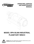
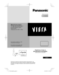
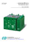
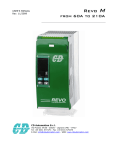
1
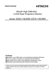
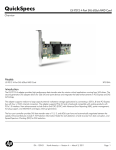
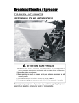
NMSB Model XI Electric Bolt Down Barrier User Manual Revision 2 Nasatka Barrier, Inc. 7702B Old Alexandria Ferry Rd Clinton, MD 20735 U.S.A. Phone: (301) 868-0300 Fax: (301) 868-0524 Nasatka Barrier, Inc. 7702-B Old Alexandria Ferry Rd. Clinton, MD 20735 (301) 868-0301 Equipment Supplied (X) NMSB Model XI Barrier (10-14ft) Right Handed o Hot Dip Galvanized o Standard Finish: Galvanized with 4” Red/White reflective Striping on Impact Side o Optional Finishes: o Solid Color – Customer preference o Sand Anti-Skid on Non-Impact Side o Reflective STOP on Impact Side o Internal Electric Drive o Power: Without EUP; All voltages o With E-UP: cannot use 110VAC single phase power o Card Reader Input (X) Dual Directional integrated Traffic Light (X) Integrated Traffic Arms (X) Access Control Loop Detectors (X) Close Access Loop Detectors (X) Dual Safety Loop Detectors (X) Tamper Control Switch (X) Master Control Panel – 24VDC (X) Remote Control Panel– 24VDC i Nasatka Barrier, Inc. 7702-B Old Alexandria Ferry Rd. Clinton, MD 20735 (301) 868-0301 Sequence of Operations The Model XI barrier and its associated electric drive system will operate in accordance with the standard Nasatka sequence of operations. The barrier will be activated via the push button controls. Secure and unsecured positions will be initiated via the push button panel (master or remote) and by a guard or other authorized person. When the barrier reaches the unsecured position the traffic arm will raise then the traffic light, if equipped, will turn yellow. When the barrier secure/close push button is activated the traffic light, if equipped, will turn red, the traffic arm will lower and the barrier will move to the secure position. The loop detectors will act as a safety keeping the barrier from moving to the closed/secure position if a vehicle is present. The emergency secure feature will be initiated by the push button panels and the system will remain secured until the operator resets the system via the reset key on the master push button panel. The emergency function will operate regardless of any safety features being active. Compliance with the instructions provided will allow for the safe operation of the system during the handling, installation, and maintenance stages and assure at the same time the proper functioning and cost-effectiveness of the machine. Nasatka Barrier, Inc. declines every responsibility for damages to things and/or persons consequences of a negligent use of the machine or to the lack of observance of the instructions contained in this manual. ii Nasatka Barrier, Inc. 7702-B Old Alexandria Ferry Rd. Clinton, MD 20735 (301) 868-0301 Table of Contents Sections Equipment Supplied .............................................................................. i Sequence of Operations........................................................................ ii 1. Warranty ..................................................................................... 1 2. Introduction ................................................................................. 2 3. Crash Rating ................................................................................ 3 4. General Description ....................................................................... 4 5. Specifications ............................................................................... 5 6. System Operation ......................................................................... 6 7. Drawings ..................................................................................... 7 8. Installation................................................................................... 8 9. Preventative Maintenance and Inspection .......................................... 9 10. Service ...................................................................................... 10 11. Residual Hazards......................................................................... 11 Appendix A – VFD (Variable Frequency Drive) Information Appendix B – Loop Detector Information iii Nasatka Barrier, Inc. 7702-B Old Alexandria Ferry Rd. Clinton, MD 20735 (301) 868-0301 1. WARRANTY Each item of equipment in the Nasatka Maximum Security Barrier is warranted by Supplier for a period of one year, after delivery F.O.B. plant, unless otherwise specified by Supplier, from failure of operation in ordinary use and against defects due to faulty material or workmanship. Any defective equipment in the Nasatka Maximum Security Barrier shall be returned to the factory, at Supplier's option, for repair or replacement, and Supplier assumes no responsibility for service at any consumer site. Supplier is in no event responsible for any labor costs under the warranty. Subject to the above limitation, all service, parts, and replacements necessary to maintain the equipment as warranted shall be furnished by Supplier at no cost to consumer. Supplier shall not have any liability under these specifications, other than for repair or replacement as described above for equipment malfunction or equipment failure of any kind, caused for any reason, including, but not limited to unauthorized repairs, improper installation, installation not performed by Supplier personnel, nor by Supplier authorized personnel, modifications, misuse, accident, catastrophe, neglect, natural disaster, act of God of if at any time the power supplied to any part of the Nasatka Maximum Security Barrier falls short or exceeds the rate of tolerance for the equipment. The exclusive remedy for breach of any warranty by Supplier shall be the repair or replacement at supplier’s option, of any defects in the equipment. IN NO EVENT SHALL THE SUPPLIER OF NASATKA MAXIMUM SECURITY BARRIER BE LIABLE FOR CONSEQUENTIAL OR SPECIAL DAMAGES OR ANY KIND OF DAMAGES TO ANYONE. Except as provided herein, Supplier makes no warranties or representations to consumer or to anyone else and consumer hereby waives all liability against Supplier as well as any other person for the design, manufacture, sale, installation, and/or servicing of the Nasatka Maximum Security Barrier. THE FOREGOING WARRANTIES ARE IN LIEU OF ALL OTHER WARRANTIES EXPRESS OR IMPLIED, INCLUDING THE IMPLIED WARRANTY OF MERCHANTABILITY AND FITNESS FOR A PARTICULAR PURPOSE. NO OTHER WARRANTIES EXIST. Any modification or alteration by anyone other than NASATKA or a NASATKA authorized personnel will render the NASATKA warranty herein as null and void. Nasatka Barrier, Inc. 7702-B Old Alexandria Ferry Rd. Clinton, MD 20735 (301) 868-0301 2. INTRODUCTION The Nasatka Maximum Security Vehicle Arrest Barrier plays a leading role in the vehicle access control industry. By utilizing the latest technology in the design of the proprietary electric drive unit and the microprocessor based electronic control system the NMSB provides performance, reliability, safety and security unmatched in the industry. Having been designed, manufactured, and approved to exceed 4,000-pound vehicle traveling at 30 mph, Nasatka will provide videocassette tapes to qualified parties who wish to witness the basic installation procedure and the stopping power of these devices. Operating security has been maximized by eliminating the decisions required by the system attendant to the level that Nasatka can provide a totally automatic system, which requires no personnel to control vehicle access. Each system is 100% factory tested and adjusted for normal installed operating conditions. The Barrier, the Electric Drive Unit, and the Electronic Controls are interconnected and run in all operating modes. This insures that each component of the NMSB is functioning in accordance with the customer’s operating parameters and the quality assurance standards of Nasatka Barrier, Inc. Nasatka's pre-procurement "check list" insures the proper system configuration and operation with the minimum expenditure of time and at the lowest possible cost. In addition, our standard system documentation contains over 30 pages of detailed, step-by-step, information pertaining to all aspects of installation, start up, trouble shooting, and maintenance. Familiarity with vehicle access systems or electronics is not required to properly install, operate, and maintain the NMSB. DISCLAIMER: All barrier systems should be carefully planned with safety as a paramount concern. This product is designed to control vehicle traffic; however, Nasatka Barrier is not a traffic safety engineering firm and recommends that a system be reviewed before installation. It is recommended that all forms of safety equipment be utilized as much as possible. Such safety equipment includes, but is not limited to, proper lighting, written warning signs, traffic lights, gate arms and/or an audible alarms, etc. Nasatka Barrier, Inc. 7702-B Old Alexandria Ferry Rd. Clinton, MD 20735 (301) 868-0301 3. CRASH RATING The NMSB Model XI has been physically crash tested and found to be capable of stopping a 4,000 lb vehicle traveling at 30 MPH. Video of the crash test is available on the Nasatka web site www.nbistop.com. Nasatka Barrier, Inc. 7702-B Old Alexandria Ferry Rd. Clinton, MD 20735 (301) 868-0301 4. GENERAL DESCRIPTION WARNING Bicycles, motorcycles and pedestrians are not allowed to pass the open barrier gates. Specific pedestrian walkways around the gate, separated by railings or fences, should be provided by the customer. 4.1 DESCRIPTION The NMSB Model XI is manufactured in several standard widths. Other widths are available upon customer request. The NMSB Model XI comes in left hand and right hand versions. The barrier’s orientation is determined by viewing the barrier’s housing from the safe side. A left hand barrier has the housing assembly located on the left and right hand barriers have the housing assembly located on the right. The Model XI contains three main components: the Main Assembly, the Gate Plate Assembly, and the Concrete Foundation. Figure 4.1 illustrates these components. All steel components of the NMSB Model XI assembly are hot dip galvanized to prevent rust. Figure 4.1 Nasatka Barrier, Inc. 7702-B Old Alexandria Ferry Rd. Clinton, MD 20735 (301) 868-0301 4.1.1 MAIN ASSEMBLY The Main Assembly includes the base and housing. The housing location is determined by the specification of either a right or a left hand barrier. The housing encloses the Electric Gear Drive, the Electric Control Box, the Electric Drive and the Traffic Arm Motor Assembly (if Applicable). The base of the main assembly secures the Housing and the Gate Plate to the Concrete Foundation. 4.1.2 GATE PLATE ASSEMBLY The Gate Plate is the essential component for maintaining security with a NMSB Model XI Barrier. With the Gate Plate in the NonSecure (Open) position, it will allow a vehicle to pass through, and in the Secure (Closed) position traffic will not be able to pass. 4.1.3 FOUNDATION PAD The NMSB Model XI requires a minimum 28 MPa (4,000 PSI) strength concrete foundation. See drawings in Section 7 for the dimensions of the foundation. Nasatka crash tested the Model XI using no rebar or mesh in the concrete foundation. Nasatka suggests the buyer to check local building codes and ensure the foundation is installed in compliance with those codes. 4.2 STANDARD EQUIPMENT The Electric Gear Drive operates the Gate Plate in accordance with the operator’s input. This gear drive consists of an electric motor, a Variable frequency drive, and a control box which includes the relays, and all other electrical/mechanical components used for the proper functioning of the system. The following is a brief description of the components: 4.2.1 ELECTRIC MOTOR AND GEARBOX The Electric Motor and Gearbox is available in many different power requirements depending on the customers need. Customer chosen power requirements will be listed in the Equipment Supplied List. Nasatka Barrier, Inc. 7702-B Old Alexandria Ferry Rd. Clinton, MD 20735 (301) 868-0301 4.2.3 VARIABLE FREQUENCY DRIVE The Variable Frequency Drive (VFD) is an electrical component used to regulate the motor system. This controller is programmable allowing the barrier to attain the certain cycle speeds of the customer. 4.2.4 CONTROL BOX The Control Box houses the CPU for the Model XI barrier. This CPU is Programmable to the customer’s specified instructions. The Control box also houses cutoff switches and all other required electrical components. 4.2.5 LOOP DETECTORS Loop Detectors are placed in the ground either before, after or at the barrier and are used to detect vehicles. The detection of a vehicle can be used to indicate to the operator or the HPU system that an action is required. For example if the detector is placed before the barrier, an alarm can be triggered when a vehicle is present to alert the operator that a vehicle is requesting access. The Loop detectors can also be wired as safety devices that will not allow the barrier to close if a vehicle is present in the path of the Gate Plate. 4.2.6 TRAFFIC ARM The Traffic Arm is a device that provides a visual indication whether or not a vehicle can safely pass the barrier. It is NOT a means to stop a vehicle. 4.2.7 TRAFFIC LIGHTS Traffic lights give a visual indication as to the status of the barrier. Red indicates Closed/Non-Passable while yellow or green indicates Open/Pass with caution. Nasatka Barrier, Inc. 7702-B Old Alexandria Ferry Rd. Clinton, MD 20735 (301) 868-0301 4.3 OPTIONAL EQUIPMENT Nasatka Barrier, Inc. realizes that our clients have different needs and therefore provides Optional Equipment to enhance the performance and operation of the NMSB Model XI. These items must be specified when ordering. Any optional items will be listed under the Equipment Supplied List. 4.3.1 PUSH BUTTON CONTROL PANELS These panels are designed to allow the operator’s input to control all automated aspects of the Model XI. A series of push buttons on the control panel operate the barrier. All of the push buttons on the control panels are fitted with small lights to illuminate the buttons and give a visual indication to the operator as to the status of the barrier with respect to its position and/or its direction of motion. 4.3.1.1 Master Push Button Control Panel The Master Control Panel is intended to be used in a secure guard house or designated location where the operator contains complete control of the barrier system. The master control panel operates on 24 VDC power, supplied by the System controller. The panel can be customized to meet the needs of each client’s particular operational requirements. 4.3.1.2 Remote Push Button Control Panel The remote control panel is essentially a user panel that can be located at any location designated by the customer for remote operation of the barrier. These panels are typically located near the barrier. The remote control panel operates on 24 VDC power, supplied by the master control panel. Nasatka Barrier, Inc. 7702-B Old Alexandria Ferry Rd. Clinton, MD 20735 (301) 868-0301 5. SPECIFICATIONS Crash Rating: NMSB Model XI = 1815 kg (4,000 lbs) at 48 kmh (30 mph) Barrier Strike Plate Material: U.S. ASTM, A514 Type-B (T-1) Yield Strength: 690 MPa (100 KSI) Tensile Strength: 760/900 MPa (110/130 KSI) Elongation (2 in.): Long 18 Trans 16 * All other materials are A36 Structural grade steel Barrier Height: In the fully secure (closed) position, the barrier strike plate height is 500 mm +/- 25mm (20” +/-1”) above grade. Barrier Dimensions: See accompanying drawings, section 7 Drawings Barrier Weight: 4.25 m (14’ foot) barrier approx. 780kg (2,200 lbs) with traffic arm (add/subtract 220 kg per meter, 150 lbs per foot) Response time: The barrier will travel to the fully closed/secure position in approximately five (5) seconds under normal operating conditions. Emergency Fast Operation, if requested, shall be about (2) second. Normal Activation: Electric motor driving a gearbox with an arm attached to the gate plate. Position Selection: The system shall be constructed such that the barrier remains in the position selected (open, closed) by the operator (i.e. no external electric or manual force shall be required to hold the barrier in the last position). Power Requirements: The power requirements for the Model XI will vary as per the customer’s requirements. The power requirements will be stated in the Equipment Supplied List. Barrier Finish: All steel components of the Model XI are hot-dip galvanized to prevent rust. In addition to the galvanized steel finish, there are various color schemes that are available. The customer’s chosen color scheme will be indicated in the Equipment Supplied List. Nasatka Barrier, Inc. 7702-B Old Alexandria Ferry Rd. Clinton, MD 20735 (301) 868-0301 Operating Modes A) Normal: Raise and operation. lower barrier, operator controlled electric B) Manual: Raise and lower barrier, no electric, operator physically raises and lowers barrier with use of drill or socket. C) Emergency: Raise barrier to "Secure" position, operator controlled electric operation. System Controller: Smart Relays with built-in timers synchronized to properly operate the barrier. Control Panel: A) Momentary switch to raise or lower the barrier. B) Audible alert, to activate whenever an emergency exists. C) Indicating lights for status of barrier position. Foundation: The NMSB Model XI requires a 28 MPa (4,000 psi) minimum strength concrete pad. See included drawing for dimensions of the foundation. Nasatka Barrier, Inc. 7702-B Old Alexandria Ferry Rd. Clinton, MD 20735 (301) 868-0301 6. SYSTEM OPERATION This section explains how to operate your NMSB Model XI barrier system. 6.1 MANUALLY SECURE AND UNSECURE The NMSB Model XI can be operated manually even if the power to the barrier has been disabled. The following are instructions explaining how to operate the NMSB Model XI barrier manually. DANGER Two persons are required to manually operate the barrier. Manual operations shall be performed with outmost care, to prevent possible crushing hazards consequence of unexpected movements of the barrier 1. Open the door on the housing and locate the control box (Figure 6.1). Slide the box out of the housing (Figure 6.2). Using the red disconnect switch located inside the control box, switch the power off. To verify that the power to the barrier has been shut off, take a reading from a volt meter. Figure 6.1 Nasatka Barrier, Inc. 7702-B Old Alexandria Ferry Rd. Clinton, MD 20735 (301) 868-0301 Figure 6.2 2. After verifying that there is no electric going to the electric motor, remove the rubber cap on the top of the motor (Figure 6.3). With the rubber cap removed, use a ½” socket to turn the motor. Turning the socket in a clockwise direction allows the barrier to lower and while turning the socket counterclockwise allows the barrier to be raised. The use of an 18V cordless drill will allow quicker manual deployment of the NMSB Model XI. Figure 6.3 Nasatka Barrier, Inc. 7702-B Old Alexandria Ferry Rd. Clinton, MD 20735 (301) 868-0301 6.2 ELECTRIC OPERATION Your barrier controls are fully customizable and may be slightly different than what is described here; however, we have tried to describe the basic operation of the barrier with a typical control layout. Electric operation is a powered mode of operation that functions via operator inputs from one of the control panels. In this mode the barrier can be raised or lowered at the push of a button. Should there ever be a power failure or power interruption of some sort the barrier may also be operated manually (nonpowered). There are four operating positions of the NMSB Model XI. They are described as follows: 1. Unsecured (Fully Open) – The barrier is in the unsecured position and traffic is allowed to pass through. 2. Secure (Fully Closed) – The barrier is in the secure position and traffic cannot pass through. 3. Intermediate 1 – The barrier is moving toward the Secure position from the unsecured position. 4. Intermediate 2 – The barrier is moving toward the unsecured (Fully Open) position from the Secure (Fully Closed) position. 6.2.1 MASTER CONTROL PANEL POWER ON SWITCH This key operated switch is located on the master control panel and allows the operator to turn on the power to the master control panel. Additionally this switch feeds power to all remote control panels associated with that master panel. When the key is in the off position it can be removed to help further secure the barrier. 6.2.2 REMOTE CONTROL SELECTOR SWITCH This key operated switch is located on the master control panel, and allows the operator to select a remote control panel for operation of the barrier. All master control panel functions remain available while any remote control panel is activated. 6.2.3 REMOTE CONTROL PANEL POWER ON SWITCH This key operated switch is located on the remote control panel, and allows the operator to turn the power to the remote panel on or off. In order for the remote panel to be powered by this switch, it must be activated by the associated remote control selector switch located on the master control panel. Nasatka Barrier, Inc. 7702-B Old Alexandria Ferry Rd. Clinton, MD 20735 (301) 868-0301 6.3.4 BARRIER OPEN BUTTON This button is a momentary (push and release) button that opens (barrier is unsecured) the barrier when pushed. The motion of the barrier to the open position can be stopped and reversed at any time by pressing the close button. 6.3.5 BARRIER CLOSE BUTTON This button is a momentary (push and release) button that closes (barrier is secured) the barrier when pushed. The motion of the barrier to the closed position can be stopped and reversed at any time by pressing the open button. 6.3.6 EMERGENCY CLOSE BUTTON This button is a protected momentary (push and release) button that closes the barrier regardless of any safety warning signals that may be received from the system. For instance, once this button is pushed the gate will close even if there is a vehicle in the safety loop. This button is protected against accidental actuation by a plastic cover. Once this button is actuated the system will only return to normal operation after being reset. 6.3.7 SYSTEM RESET ON MASTER PANEL This key operated switch is located on the master control panel, and must be actuated after use of the Emergency Close function to return the system to normal operation. 6.3.8 INDICATOR LIGHTS Various indicator lights are available on the panels. Some typical lighting arrangements include: 1) closed and open lights which indicate the barrier is in the closed or open position; 2) power indicator lights which indicate power is on to the system, the master panel or the remote panel; 3) emergency operation light, which indicates the system is in emergency operation mode. Emergency lights are extinguished when the system reset is actuated. 6.3.9 ALARMS The control panels may also be equipped with alarms that indicate the system is in the emergency operation mode. These alarms are quieted and reset when the system reset is actuated. Additional alarms are available for features such as barrier left in the unsecured position for an extended length of time, wrong way approach, and over speed approach. Nasatka Barrier, Inc. 7702-B Old Alexandria Ferry Rd. Clinton, MD 20735 (301) 868-0301 6.4 STANDARD OPERATING CONDITIONS The operator can trigger one of three inputs (i.e., Emergency Close, Close, or Open). The results of those inputs are given below. DANGER During the Emergency Close mode, all the safety devices (loop detectors) are overridden. To prevent possible hazards, only trigger the Emergency Close mode when it is really needed. The Emergency Close mode shall not be used as a standard procedure to secure the barrier. 6.4.1 BARRIER IS FULLY OPEN (UNSECURED) Operator Input Emergency Close Close Open 6.4.2 Result Barrier and traffic arm move to secure position in approx. two (2) seconds. An alarm sounds continuously, until manual (key) reset of the system. Barrier and traffic arm move to the fully secure position in standard operating time. No Action BARRIER IS FULLY CLOSED (SECURE) Operator Input Emergency Close Close Open Result Alarm sounds continuously, until manual (key) reset of the system. No action. Barrier and traffic arm move to the fully open position in standard operating time. Nasatka Barrier, Inc. 7702-B Old Alexandria Ferry Rd. Clinton, MD 20735 (301) 868-0301 6.4.3 BARRIER IS BETWEEN OPEN AND CLOSED AND MOVING TOWARD CLOSED/SECURE POSITION Operator Input Emergency Close Close Open 6.4.4 Result Barrier and traffic arm move to secure position in approx. two (2) seconds. An alarm sounds continuously, until manual (key) reset of the system. Barrier and traffic arm continue toward the fully secure position in standard operating time. Barrier and traffic arm immediately reverse direction of travel and move to the fully open position in standard operating time (slightly faster due to reduced travel). BARRIER IS BETWEEN OPEN AND CLOSED AND MOVING TOWARD OPEN/UNSECURED POSITION Operator Input Emergency Close Close Open Result Barrier and traffic arm immediately reverse direction of travel and move to the secure position in approx. two (2) seconds. An alarm sounds continuously, until manual (key) reset of the system. Barrier and traffic arm immediately reverse direction of travel and move to the fully secure position in standard operating time (slightly faster due to reduced travel). Barrier and traffic arm continue toward the fully open position in standard operating time. Nasatka Barrier, Inc. 7702-B Old Alexandria Ferry Rd. Clinton, MD 20735 (301) 868-0301 6.5 ADDITIONAL OPERATIONAL FEATURES 6.5.1 CLOSE LOOP DETECTORS (SAFETY) The NMSB Model XI barrier is equipped with loop detectors to prevent the barrier from rising when a vehicle is on the loop in the roadway. The detector has an indicating light on the front face for power status and a vehicle present status light. The output of the detector will prevent the barrier from rising when vehicle is present over a loop except when the Emergency button is activated, and then the safety will be ignored. 6.5.2 SPEED LOOP DETECTORS The speed loop detectors register the speed of the car before getting to the barrier. If the car is traveling at a speed greater than what the customer has specified, an alarm will be activated on the control panels alerting the guard. 6.5.3 WRONG WAY LOOP DETECTORS The wrong way loop detectors inform the guard of a car traveling in the wrong lane of traffic. When the car passes the loop detectors an alarm is activated on the control panels to alert the guard. Nasatka Barrier, Inc. 7702-B Old Alexandria Ferry Rd. Clinton, MD 20735 (301) 868-0301 7. DRAWINGS Nasatka Barrier, Inc. 7702-B Old Alexandria Ferry Rd. Clinton, MD 20735 (301) 868-0301 Nasatka Barrier, Inc. 7702-B Old Alexandria Ferry Rd. Clinton, MD 20735 (301) 868-0301 SECURE SIDE IMPACT DIRECTION Nasatka Barrier, Inc. 7702-B Old Alexandria Ferry Rd. Clinton, MD 20735 (301) 868-0301 SECURE SIDE IMPACT DIRECTION Nasatka Barrier, Inc. 7702-B Old Alexandria Ferry Rd. Clinton, MD 20735 (301) 868-0301 3 Nasatka Barrier, Inc. 7702-B Old Alexandria Ferry Rd. Clinton, MD 20735 (301) 868-0301 6 Nasatka Barrier, Inc. 7702-B Old Alexandria Ferry Rd. Clinton, MD 20735 (301) 868-0301 Nasatka Barrier, Inc. 7702-B Old Alexandria Ferry Rd. Clinton, MD 20735 (301) 868-0301 Nasatka Barrier, Inc. 7702-B Old Alexandria Ferry Rd. Clinton, MD 20735 (301) 868-0301 Nasatka Barrier, Inc. 7702-B Old Alexandria Ferry Rd. Clinton, MD 20735 (301) 868-0301 Nasatka Barrier, Inc. 7702-B Old Alexandria Ferry Rd. Clinton, MD 20735 (301) 868-0301 Nasatka Barrier, Inc. 7702-B Old Alexandria Ferry Rd. Clinton, MD 20735 (301) 868-0301 Nasatka Barrier, Inc. 7702-B Old Alexandria Ferry Rd. Clinton, MD 20735 (301) 868-0301 Nasatka Barrier, Inc. 7702-B Old Alexandria Ferry Rd. Clinton, MD 20735 (301) 868-0301 Nasatka Barrier, Inc. 7702-B Old Alexandria Ferry Rd. Clinton, MD 20735 (301) 868-0301 Nasatka Barrier, Inc. 7702-B Old Alexandria Ferry Rd. Clinton, MD 20735 (301) 868-0301 Nasatka Barrier, Inc. 7702-B Old Alexandria Ferry Rd. Clinton, MD 20735 (301) 868-0301 Nasatka Barrier, Inc. 7702-B Old Alexandria Ferry Rd. Clinton, MD 20735 (301) 868-0301 Nasatka Barrier, Inc. 7702-B Old Alexandria Ferry Rd. Clinton, MD 20735 (301) 868-0301 HYD RAULIC PUM P UN IT H OUSING RE MO TE PANEL M ASTER PANEL GR ADE D A SAFETY LOO P (VEHICLE D ETECTOR ) 1 TW ISTED P AIR C ABLE M ULTI-CO NDU CTOR 18 AW G SH IE LD ED CABLE (1 AM P M AXIM UM @ 24 VAC) M OTO R POW ER 120V/1PH/60H Z CON TROL PO W ER 120V/1PH/60H Z (15A) B C SAFETY LOO P (VEHICLE D ETECTOR ) 1 TW ISTED P AIR C ABLE C CONDUIT A B C D SIZE 3/4" 3/4" 1/2" 3/4" DESCRIPTION C ON TR OL CO NN EC TIO NS B ET WE EN H PU HO US ING A ND MA ST ER C ONT RO L P AN EL P OW E R C ON NE CT ION S FRO M HP U HO USING TO SITE FE ED S AF ET Y LOO P CO NN EC TIO N TO HP U H OU SIN G C ON TR OL CO NN EC TIO N BE TW EE N MA ST ER PA NE L A ND R EM OT E C ON TRO L P AN EL Nasatka Barrier, Inc. 7702-B Old Alexandria Ferry Rd. Clinton, MD 20735 (301) 868-0301 HYDRAULIC PUMP UNIT HOUSING HYDRAULIC PUMP UNIT HOUSING REMOTE PANEL MASTER PANEL GRADE D GRADE 120V/1PH/60HZ A SAFETY LOOP (VEHICLE DETECTOR) 1 TWISTED PAIR CABLE MULTI-CONDUCTOR 18 AWG SHIELDED CABLE (1 AMP MAXIMUM @ 24 VAC) MOTOR POWER 120V/1PH/60HZ CONTROL POWER 120V/1PH/60HZ (15A) B C SAFETY LOOP (VEHICLE DETECTOR) 1 TWISTED PAIR CABLE C CONDUIT A B C D SIZE 3/4" 3/4" 1/2" 3/4" DESCRIPTIO N CONTRO L CONNEC TIO NS BETW EEN HP U HO USING AND MASTER CONTROL PANEL POW ER CONNE CTIONS FROM HPU HOUSING T O SITE FEED SAFET Y LOOP CONNECTION TO HPU HOUSING CONTRO L CONNEC TIO N B ETW EEN MAST ER PANEL AND REMOTE CONTROL PANEL Nasatka Barrier, Inc. 7702-B Old Alexandria Ferry Rd. Clinton, MD 20735 (301) 868-0301 HINGE SIDE P OWER EMERG ENCY CLO SE RESET R EMOT E CLO SE O PEN 0 Nasatka Barrier, Inc. 7702-B Old Alexandria Ferry Rd. Clinton, MD 20735 (301) 868-0301 0 Nasatka Barrier, Inc. 7702-B Old Alexandria Ferry Rd. Clinton, MD 20735 (301) 868-0301 HIN G E S IDE POW ER EM ER G EN CY C LO SE CLO S E O P EN 0 Nasatka Barrier, Inc. 7702-B Old Alexandria Ferry Rd. Clinton, MD 20735 (301) 868-0301 0 Nasatka Barrier, Inc. 7702-B Old Alexandria Ferry Rd. Clinton, MD 20735 (301) 868-0301 Nasatka Barrier, Inc. 7702-B Old Alexandria Ferry Rd. Clinton, MD 20735 (301) 868-0301 Nasatka Barrier, Inc. 7702-B Old Alexandria Ferry Rd. Clinton, MD 20735 (301) 868-0301 Loop Dimensions Several points are to be considered for proper loop dimensioning: Loop Perimeter The loop perimeter is calculated from 2 X (Length A + Length B). The loop perimeter must have a minimum of 13 FT and a maximum of 82 FT. The loop size must be adapted for each individual installation type. The maximum loop sensitivity is achieved when the loop is slightly smaller then the vehicles passing this lane (i.e. Cars, Trucks, Trailer Trucks etc.). Loops that are wider then the vehicle have a decreased sensitivity. Length to width Radio The Length to Width Radio is a result of Length A / Length B. This Ratio must not exceed 4 : 1. Number of Windings (Turns) The recommended turns of the loop wire depends on the loop perimeter. Nasatka Barrier recommends the following: Loop Perimeter 13 ft - 23 ft 23 ft – 39 ft 39 ft – 80 ft Number Turns 5 Turns 4 Turns 3 Turns Loop Lead Wire The loop lead wire has a significant role to the functionality of the loop. Following are some important points for installing loop leads: The loop lead wire must be twisted approximately 7 times per 1 foot up to the point where the wires connect to the detector. Leads of multiple loops should not use the same conduit. If it is impossible to have separate conduits for multiple loop leads a shielded twisted pair wire must be used for each loop. The lead length should not exceed 50feet. Long leads can decrease the sensitivity therefore the leads should be as short as possible. Do not run a loop lead through the same cut of another loop lead. Note: A minimum distance of 12” between the loop and metal objects (steel reinforcements, sewer grill etc.) must be kept. If this is not the case the loop sensitivity can degrease significantly and a proper functioning of the loop cannot be guaranteed. The loop and loop leads must not be installed near to any underground high voltage cable. The distance between loops and barrier housings or barrier arms should be greater then 10”. It is a must to cut the leads to the proper length. Excessive long leads looped before it is wired to the detector will decreased the loop functionality. Usage of Pre-Manufactured Loops Any pre -manufactured (formed) loop can be used as long they meet our this manual. requirements explained in Self-Made Loops Alternatively, a loop can be manu factured from a single AWG 18 solid or stranded insulated wire. The inductance of the loop must lie between 70 and 500 µH, which is usually achieved by producing three to five windings in the coil. The loop resistance should be lower then 2 Ω. The loop resistance should be measured after installing the loop but before sealing. The Loop Insulation Resistance must be measured to earth ground. The Insulation Resistance against earth ground must be a minimum of 1M Ω. If this is not the case the lo op insulation might be damaged. (See Number of windings, Turns). The temperature of the sealing must be below the temperature of the wire insulation. 0 Nasatka Barrier, Inc. 7702-B Old Alexandria Ferry Rd. Clinton, MD 20735 (301) 868-0301 Nasatka Barrier, Inc. 7702-B Old Alexandria Ferry Rd. Clinton, MD 20735 (301) 868-0301 8. INSTALLATION The Installation of the NMSB Model XI is not difficult. We have designed the Model XI barrier to require minimal effort to install. Four basic steps are required and explained in this section for the installation of the barrier. Those steps include 1) excavation for the foundation, 2) setting and aligning the barrier, 3) trenching locations for power and connecting the power, 4) Traffic Arm installation. 8.1 STANDARD MATERIALS The NMSB Model XI requires the following for installation of the Hydraulic barrier: 1. Approximately 1.5 cubic meter (2 cubic yards) of 28 MPa (4,000 PSI) minimum strength concrete. 2. A crane or other suitable lifting device with an appropriate capacity. See Section 5 for your barriers length and weight. DANGER Load, unload and handle the barrier always paying the utmost attention to possible hazards, in particular make sure that there are no persons or things in the range of the lifting device. 8.2 FOUNDATION INSTALLATION The foundation installation guidelines are not meant to supersede local building codes instead they are provided as a guidance to help insure proper barrier operation. 1. Referring to Section 7, excavate the required lengths indicated on the drawings. 2. Run the conduit piping to their respective locations as indicated from the drawings in Section 7. The piping size used for conduit must be a minimum of 9mm diameter (¾”). It is suggested to place the conduit no less than 150 mm (6 inches) below grade. One cutout measuring 125 mm x 125 mm (3” x 5”) is provided in the base of the main assembly as the “stub-up” access for the conduit which will contain the control wiring as well as carry the primary power supply. 3. Pour the 28 MPa (4,000 PSI) minimum concrete into the excavated ditch with the conduit piping in place. The concrete shall be level and flush to the road’s surface. The concrete must be fully cured prior to installation of barrier. 4. Using a suitable lifting device, place barrier onto concrete pad. Make sure the “stub-up” and bottom of housing align while lowering barrier. 5. After the barrier has been lowered onto the concrete pad, align as to the drawings found in Section 7. 6. Using the holes in the Gate Plate as a guide, drill Ø25 mm (Ø1”) holes in the concrete 140 mm (5 ½”) deep. All mounting holes in the barrier shall be used. After all holes are drilled, flush drilled holes out with pressurized water cleaning out all debris from inside the hole. After flushing holes with water, vacuum remaining water and debris from all holes. Make sure all debris and water has been fully removed. Allow holes to completely dry before continuing. 7. Pour epoxy into each hole prior to inserting threaded rods. Place grade 8.8 M24 x 150 mm long (or equivalent grade 8, Ø7/8” – 9NC x 6” long) threaded rod in each epoxy filled hole. Allow epoxy to set for required time as stated on epoxy bottle prior to commissioning the use of the barrier. All hardware to secure this barrier to the concrete pad shall be coated to endure outside elements/weather. Be sure that rods have enough thread engagement for the washer and nut which will hold the barrier down to the concrete pad. 8. Torque nuts to 440 N·m (322 Ft-Lbs) of torque in all locations. It will be better to start in the middle and work outwards when tightening the nuts. 8.3 ELECTRICAL INSTALLATION When wiring the barrier, national and local electric codes must be adhered to and work completed by an appropriately qualified electrician. Refer to Section 7 for electrical wiring schematics and logic diagrams. ATTENTION Do not connect the barrier to the electric line before having verified that the line itself is completely compliant to the enforced norm. Also make sure that the electric line can supply the needed power and that: - there is a properly working grounding circuit - there is a properly working protection circuit 8.4 TRAFFIC ARM INSTALLATION The Traffic arm motor assembly is installed prior to shipment. Only the Traffic Arm itself and mounting hardware need to be installed upon delivery of the barrier. (See Figures 8.4.1 and 8.4.2) Figure 8.4.1 1. Installing Traffic Arm starts with unpacking all hardware and unpacking the arm components. The aluminum Traffic Arm may need to be trimmed to size of barrier using a metal cutting saw. Depending on length of Traffic Arm this may require two people. 2. Install Mounting Bracket using the (2) provided Mounting Bracket Screws. 3. Place Internal Support into Traffic Arm and slide all (4) Traffic Arm Bolts through both the Traffic Arm and Internal Support. 4. Align and tighten Traffic Arm Bolts to Mounting Bracket which is located on the barrier. 5. Once traffic arm is mounted; align arm parallel to barrier or grade. 6. Loosen the two Traffic Arm Adjusting Screws slightly using an Allen wrench. These can be accessed from inside the barrier housing. 7. Level the arm and tighten the two Traffic Arm Screws. 8. Place End Cap on the end of the Traffic Arm. Figure 8.4.2 9. PREVENTATIVE MAINTENANCE AND INSPECTION WARNING POWER MUST BE TERMINATED WHILE SERVICING OR MAINTAINING THE BARRIER. It is imperative that personnel involved in the installation, service, and operation of the barrier be familiar with how the equipment is to be used, and the limitations of the system and its components. The personnel shall also have knowledge of good mechanical practices in terms of safety, installation, and maintenance of the barrier. As with any machine, Preventative Maintenance and Inspection (PM&I) is a key factor in keeping the NMSB Model XI running smoothly and ensuring a long service life. If maintained properly, the NMSB Model XI should last for thousands of cycles. Barriers that are not routinely used should be cycled weekly. This section provides descriptive information on maintaining and inspecting the NMSB Model XI barrier, as provided by Nasatka Barrier, Inc. Additionally, a Preventative Maintenance and Inspection check list is provided at the end of this section. Below are a few key components of the Model XI that need to be frequently checked (see Figure 9.1). FIGURE 9.1 9.1 INSPECT AND CLEAN THE MECHANICAL SYSTEM Mechanical Operation PM&I applies to all NMSB Model XI’s. The mechanical system on the NMSB Model XI should be inspected every 100 hours of operation or monthly, whichever is sooner. When inspecting the barrier be sure that unauthorized personnel and vehicles are clear of the barrier. With the barrier in the unsecured position inspect and maintain the following: • Ensure the Gate Plate is not interfering with anything that could inhibit the barrier from operating. • If your barrier has an attached Traffic Arm make certain that it is functioning properly. • If your barrier has been ordered with a Traffic Light, ensure that it is properly working. • Verify that the Gate Plate rests correctly in the Hinges on the Housing Base. If the Gate Plate is not aligned correctly, it will bind making the Gate Plate operate poorly (See Figure 9.2). FIGURE 9.2 • Make sure that the nuts and bolts that are securing the Gate Plate are torqued (approximately 200psi See Figure 9.3). Check that the bolts securing the gate plate to the base plate are tight (Figure 9.4). Check the bolts that attach the motor to the housing and base. FIGURE 9.3 FIGURE 9.4 • Tighten the set screws on the small arm attached to the motor shaft. • FIGURE 9.5 9.1.1 CLEANING UNDER GATE PLATE Keeping debris clear from the hinge, the Gate Plate, and the inside of the housing is important so the NMSB Model XI is able to provide efficient performance. Monthly cleaning of the Gate Plate is a must. • Place the barrier in the secure (up) position. • Place Gate Lock Clip on outside of Gate Plate to secure the Gate Plate from accidentally lowering while personnel are working on the barrier (Figure 9.6). • Unlock and open the housing door. • Terminate the power. • Remove debris from under Gate Plate, Hinges, and moving components outside the barrier housing. Use of a pressure washer is recommended. FIGURE 9.6 9.1.1 CLEANING THE INSIDE OF THE HOUSING Keeping the inside of the housing clean and free from debris is important so the barrier can function at its best. The following are steps to guide you with this process. • Terminate the power to the barrier before doing anything inside the housing. • Open the housing door and remove any debris including sticks, stones, leaves, ext… 9.2 CYCLING THE BARRIER Before cycling the barrier, clear all traffic and nonessential personal from the area. As part of the PM&I process the barrier should be cycled regardless of power operation or manual operation capability. For electrically driven barriers, turn the power supply key switch on the master panel to “ON”. Cycle the barrier a minimum of three times using the control buttons on the panel. Verify that the barrier deploys in approximately 5-7 seconds and retracts in approximately 5-7 seconds. If the barrier requires more than 15 seconds to retract or deploy see “Section 10.1 Service – Speed Adjustment”. DANGER Only trained and authorised personnel should be allowed to adjust the setting the speed of the barrier. Verify that the Limit Switch is set properly and functioning correctly. The Limit Switch serves two functions: one, to terminate power to the motor upon reaching the fully down position; and two, to change the signal light from red to yellow. Cycle the barrier from the up position to the down position and confirm the following: • Barrier is reaches fully down (Non-Secure) position and power to the motor is terminated. • Signal light changes from red to yellow • Display screen on the CPU (central processing unit) located inside the grey electrical enclosure, will read “DN Limit”. If “DN Limit is not displayed, or if the motor stops and the traffic light has changed, but the barrier plate is not fully down, or if the light does not change and the motor continues to run after the barrier is fully down, then a slight adjustment to the limit switch is necessary. (See section 9.3.3) 9.3 MANUAL OPERATION Verify that the Barrier can be manually operated. Refer to Section 6.1, for instructions on Manual Operation. DANGER Two persons are required to manually operate the barrier. Manual operations shall be performed with outmost care, to prevent possible crushing hazards consequence of unexpected movements of the barrier 9.4 CHECKING THE ELECTRICAL SYSTEM The electrical system requires PM&I to ensure all functions are operating in accordance with the anticipated results. Some aspects of the electrical system are not required to function unless there is an emergency. These functions may not be used on a regular basis and therefore need to be tested during the 100 hour inspection. Verify the limit switches are set properly and functioning correctly. The limit switches serve three functions; 1) Terminate power to the motor upon reaching the full secured or unsecured position; 2) Change the Signal Light (Optional) from red to yellow or yellow to red; 3) Signals the Traffic Arm (Optional) to raise or lower. The system will not terminate power to the motor in the secured position until a signal is received from the limit switch. 1) 2) 3) Cycle the barrier from the secure/up position to the unsecured/down position and confirm the following: 9 Barrier reaches full unsecured position and power to the motor is terminated. 9 Signal light changes from red to yellow. Display screen on the CPU (central processing unit) located inside the Housing Enclosure, will read “DN Limit”. If “DN Limit is not displayed, then the limit switch requires adjustment or replacement. If the motor stops and the light changes, but the barrier is not fully down/unsecured, then a slight adjustment to the limit switch is necessary. If the light does not change and the motor continues to run after the barrier is fully unsecured, then a slight adjustment to the limit switch is necessary. Cycle the barrier from the unsecured/down position to the secure/up position and confirm the following: 9 Barrier reaches full secured position and power to the motor is terminated. 9 Signal light changes from yellow to red. Display screen on the CPU (central processing unit) located inside the Housing Enclosure, will read “UP Limit”. If “UP Limit is not displayed, then the limit switch requires adjustment or replacement. If the motor stops and the light changes, but the barrier is not fully secured, then a slight adjustment to the limit switch is necessary. If light does not change and the motor continues to run after the barrier is fully secured, then a slight adjustment to the limit switch is necessary. Inspect the loop detector cabling and confirm the loop detectors are functioning properly. See Appendix A for guidelines on testing the loops. 4) 5) 6) 7) Verify that the barrier moves to the unsecured position in approximately 5-7 seconds. If barrier requires more than 10 seconds to reach the unsecured position see Section “Service – Speed Control”. Confirm the normal down time of the barrier is approximately 5-7 seconds. Confirm the master panel and all its controls are functioning properly. If applicable, confirm that the EFO (Emergency Fast Operation) is properly working. ATTENTION Before opening the control panel enclosure make sure that the power line is disconnected and that the On/Off Switch is set on the Off position. 9.4.1 CONTROL PANELS Verify all buttons are functional on both Master Control and Remote Panels if applicable. Verify all illuminated switches and or lights are functioning properly on the control panels (Figure 9.4.1). Figure 9.4.1 • • • • • • Up Down E-Up (Optional) On/Off Switch Reset Switch Remote Switch (Optional) • • • • • • 9.4.2 LOOP DETECTORS (OPTIONAL) Most systems are equipped with safety loop detectors both forward and aft of the barrier within the roadway. These are essential safety devices to prevent accidental deployment of the barrier on vehicles. Visually inspect the embedded loop for any section of wire that may be exposed. If any part of the loop has been exposed check for any breaks, cuts or exposed wire in the loop. Replace or repair as needed and properly reinstall the loop in the roadway. Check continuity of the wire with a voltmeter. Verify that the loops are working correctly. See Appendix A for guidelines on testing the loops. 9.4.3 LIMIT SWITCH The limit switches (Figure 9.11) provide a signal to the controller (CPU) that the Barrier has reached the down/unsecured or up/secure position. The limit switches are factory set and are activated by making contact with the plate or cylinder when the barrier is secure or unsecured. Vibration from shipping or operation of the barrier may cause the limit switches to move slightly from their original positions. Should this happen refer to section 10.2.1 for instructions on adjusting the limit switch. Upon activating a limit switch: The Signal light (if applicable) will turn from red to yellow when unsecured and the Traffic Arm will rise. The Signal light (if applicable) will turn from yellow to red when secure and the Traffic Arm will lower. 9.5 MONTHLY CHECKLIST CHECK LIST FORM Monthly Maintenance FORM No. XI Barrier Location: Dual Single Serial No.: Inspected By: Date Check: / / Date: / Barrier Information Description 1. Barrier Appearance 2. Clean Hinge Areas 3. Stop Decal on Barrier Front 4. Anti-Skid on Barrier Plate 5. Barrier Plate Level when down 6. Motor and Gearbox securely fastened 7. Gearbox has sufficient oil 8. Pins and bushings not worn 9. Barrier E-up Cycle (1.5 seconds) 10. Barrier Reset of E-up Operation 11. Barrier Up Cycle (3-5 seconds) 12 .Barrier Down Cycle (3-10 seconds) 13. Up Speed Adjustment 14. Down Speed Adjustment 15. Housing Door Handle/Lock 16. Gate Arm System 17. Gate Arm Boom 18. Clean Around and Under Gate Plate 19. E-up light and alarm 20. Remote Panel 21 Down Limit Switch 22. Power key 23. E-up button 24. Up button 25. Down button 26. Power Light 27. Red Indicating Light 28. Reset Key Switch 29. E-up light and alarm 30.Grease Hinges if noisy Noted Items: Signed by: 1 2 3 4 Description 1 2 3 4 31. CPU Computer 32. Motor Relay 33. Light Relay 34. Clean Control Panel 35. Safety Loop Detector 36. Front Loop 37. Rear Loop 38. Traffic Light Operation 39. Red Traffic Light 40. Yellow Traffic Light 41. Master Panel 42. Power key 43. E-up button 44. Reset key 45. Up button 46. Down button 47. Power Light 48. Red Indicating Light 49. Yellow/Green Indicating Light / 10. SERVICE This section is devoted to giving detailed instructions on how to repair and service certain components from your Model XI Barrier. ATTENTION Always wear suitable protective devices (gloves, shoes…) before performing any service, installation and assembly operation on the barrier. DANGER Only trained and authorised personnel should be allowed to service the barrier. 10.1 SPEED CONTROL ATTENTION Before opening the control panel enclosure make sure that the power line is disconnected and that the On/Off Switch is set on the Off position. 10.1.4 SPEED CONTROL The speed control is set by the VFD (Variable Frequency Drive) settings. Refer to Appendix A for information on the drive. ATTENTION Only trained and authorised personnel should be allowed to adjust the barrier speed. Factory settings are the best tested solution for most of the common working environments and should be changed only if this is really needed. 10.2 ADJUSTING THE LIMIT SWITCHES (IN CLOSED/SECURE POSITION) When the barrier is in the up/secure position the display screen on the CPU will read “UP limit” as soon as the barrier plate trips the limit switch (See Figure 10.2.1 and 10.2.2). ATTENTION Before opening the control panel enclosure, make sure that the power line is disconnected and that the On/Off Switch is set on the Off position. • • • If the barrier is in the secure position and “UP limit” is NOT displayed, try to manually trigger the limit switch. If this is successful then a slight adjust of the limit switch is required. 9 Terminate Power to the barrier. 9 Loosen limit switch mounting screws. 9 Slide the limit switch in the slotted bracket in the appropriate direction to ensure it engages. Slight adjustments (2-3 mm or less) are all that should be required. 9 Turn Power back on and cycle barrier and verify limit switch is functioning correctly. Repeat steps as necessary to obtain proper placement of limit switch. If the limit switch cannot be triggered manually, the limit switch may need to be replaced. Check continuity prior to replacing. Check to make sure Traffic Lights are functioning properly and bulbs are good. FIGURE 10.2.1 11. RESIDUAL HAZARDS All the various stages - Designing, Construction, Selection of the sub-contractors and Final Inspection - involving the manufacturing processes of the Nasatka Maximum Security Vehicle Arrest Barrier model XI were carried out with the utmost care and attention to assure compliance of the product with the strictest safety standards through its high mechanical and engineering quality. It is, however, necessary to specify that, notwithstanding: • the attentions taken in the designing phase; • the care and control given to the manufacturing process; the barrier object of this manual has, however, some risks that, for the specific type of job to execute, cannot be completely eliminated with the aid of security systems. Such risks are later on listed. It is absolutely necessary therefore that the operator is informed and that uses the machine with the maximum precaution. DANGER It is mandatory to the owner of the machine and/or the person in charge of it, to supply to the final user all the necessary information and aids to the safeguard of its physical health. DANGER Any person allowed to control the barrier shall be given copy of this manual; the owner of the machine shall make sure that any person allowed to use the machine has fully read and understood the present manual, therefore knowing how to use the machine in safe conditions. A safe use is guaranteed only meticulously following the instructions listed in this manual. WARNING Bicycles, motorcycles and pedestrians are not allowed to pass the open barrier gates. Specific pedestrian walkways around the gate, separated by railings or fences, should be provided by the customer. 11.1 CRUSHING HAZARD This hazard is present while deploying the barrier from the secure position. Before deploying the barrier, the user shall make sure that nobody is in the immediate vicinities of the barrier. A traffic arm is typically installed just before the barrier’s Gate and act as a holding point, considerably reducing the risk of injuries of eventual persons staying too close to the barrier. 11.2 HAZARD OF THE VEHICLE TO HIT THE BARRIER This hazard is present while securing the barrier. The Traffic Arm is a device that provides a visual and can help indicate whether or not a vehicle can safely pass the barrier. It is NOT a means to stop a vehicle. Traffic arms are typically installed in a location just before the barrier’s Gate Plate and act as a holding point for the vehicle. The Loop Detectors, placed in the ground either before, after or at the barrier, are used to detect vehicles. The Loop detectors are wired as safety devices that will not allow the barrier to close if a vehicle is present in the path of the Gate Plate. The loop detectors may not be able to detect the presence of small vehicles (bicycles or motorcycles) or of pedestrians. The loop detectors will be overridden in the event of an emergency close input. As an optional, visual signs (e.g. traffic light) give an additional help to indicate whether or not a vehicle can safely pass the barrier 11.3 PINCHING HAZARD This hazard is present while deploying the barrier from the secure position in the area where the support bar holds against the barrier base. Before deploying the barrier, the user shall make sure that nobody is in the immediate vicinities of the barrier. Visual signs (red/white stripes) and hazard labels mark the potentially dangerous areas. Figure 11.1 11.4 NOISE HAZARD In normal working conditions and if a regular maintenance is properly executed, the noise generated during the use of the barrier is neglectable and, as such, does not represent a risk for the user. Eventual optional devices installed on the barrier, such as sound warning devices, may generate a noise level that could require the use of means of protection – check the use and maintenance manual of such tools for additional information. 11.5 ELECTRICAL HAZARD This hazard can cause injury or death from electro shock or burn and can be caused by contact with live parts or parts that have become live under fault conditions as a result of an insulation failure. This hazard is present whenever the power line is connected to the barrier control box. ATTENTION Do not connect the barrier to the electric line before having verified that the line itself is completely compliant to the enforced norm. Also make sure that the electric line can supply the needed power and that: - there is a properly working grounding circuit - there is a properly working protection circuit ATTENTION Before opening the control panel enclosure, make sure that the power line is disconnected and that the On/Off Switch is set on the Off position. 11.6 HAZARD GENERATED BY SUBSTANCES This hazard is resulting from the contact with the skin and eyes of the hydraulic oil. This hazard is present in the event of a failure of the hydraulic line or while servicing the barrier. If the hydraulic circuit is pressurized, the oil could be ejected at high speed. ATTENTION Always wear suitable protective devices (gloves, shoes…) before performing any service, installation and assembly operation on the barrier. DANGER Before removing any hydraulic component, make sure that there is no pressure in the circuit or in the accumulator. If oil or sprayed oil mist gets in contact with skin or eyes, clean immediately and ask for medical assistance. 11.7 GENERIC HAZARD DANGER Any other use or operation not in compliance with this manual could cause damages to the user and or to the barrier. An un-forecasted and unexpected use alters the technical characteristics for which the barrier has been designed and manufactured and could then compromise its correct and safe use. DANGER Never perform any kind of service and/or maintenance operation to the barrier, during its normal use Appendix A VFD (Variable Frequency Drive) Information Appendix B Loop Detector Information