1
AX5400PA/PB
16 Ch. Isolated Digital Output Card
with PCI Bus
User’s Manual
Disclaimers
The information in this manual has been carefully checked and is believed to
be accurate. AXIOMTEK Co., Ltd. assumes no responsibility for any
infringements of patents or other rights of third parties which may result
from its use.
AXIOMTEK assumes no responsibility for any inaccuracies that may be
contained in this document. AXIOMTEK makes no commitment to update or
to keep current the information contained in this manual.
AXIOMTEK reserves the right to make improvements to this document
and/or product at any time and without notice.
No part of this document may be reproduced, stored in a retrieval system, or
transmitted, in any form or by any means, electronic, mechanical,
photocopying, recording, or otherwise, without the prior written permission
of AXIOMTEK Co., Ltd.
Copyright 2000 by AXIOMTEK Co., Ltd.
All rights reserved.
June 2000, Version A2
Printed in Taiwan
ii
ESD Precautions
Integrated circuits on computer boards are sensitive to static
electricity. To avoid damaging chips from electrostatic discharge,
observe the following precautions:
! Do not remove boards or integrated circuits from their anti-static
packaging until you are ready to install them.
! Before handling a board or integrated circuit, touch an unpainted
portion of the system unit chassis for a few seconds. This helps to
discharge any static electricity on your body.
! Wear a wrist-grounding strap, available from most electronic
component stores, when handling boards and components.
Trademarks Acknowledgments
AXIOMTEK is a trademark of AXIOMTEK Co., Ltd.
IBM is a registered trademark of International Business
Machines Corporation.
MS-DOS, Microsoft C and QuickBasic are trademarks of
Microsoft Corporation.
TURBO C is a trademark of Borland Inc.
BASIC is a trademark of Dartmouth College.
Intel is a trademark of Intel Corporation.
Other brand names and trademarks are the properties and
registered brands of their respective owners.
iii
Unpacking
The AX5400PA/PB is packed in an anti-static bag. The board
has components that are easily damaged by static electricity. Do
not remove the anti-static wrapping until proper precautions
have been taken. Safety instructions in front of this User’s
Manual describe anti-static precautions and procedures.
After unpacking the board, place it on a raised surface and
carefully inspect the board for any damage that might have
occurred during shipment. Ground the board and exercise
extreme care to prevent damage to the board from static
electricity.
Integrated circuits will sometimes come out of their sockets
during shipment. Examine all integrated circuits, particularly the
BIOS, processor and keyboard controller chip to ensure that they
are firmly seated.
After unpacking the AX5400PA/PB, check and see if the
following items are included and in good condition. If any of the
items is missing or damaged, notify your dealer immediately.
!
!
!
!
!
AX5400PA/PB Board
AS59099 DAC Driver CD
Cable 50P 31cm
AX5400PA/PB User‘s Manual
Warranty Card
Make sure that all of the items listed above are present.
What To Do If There Is A Problem
If there are damaged or missing parts, contact your supplier
and/or dealer immediately. Do not attempt to apply power to the
board if there is damage to any of its components.
iv
Table of Contents
Chapter 1 Introduction
1.1
1.2
Features............................................................ 2
Specifications ................................................... 3
1.2.1
1.2.2
1.2.3
1.2.4
1.2.5
1.3
AX5400PA ........................................................
AX5400PB .........................................................
Interface Characteristic ................................
Power Requirements.......................................
Physical/Environmental ..................................
3
3
3
3
4
Applications...................................................... 4
Chapter 2 Installation
2.1
2.2
Base I/O Port Address ...................................... 5
User Connections ............................................. 5
2.2.1
2.2.2
2.2.3
2.3
2.4
AX5400PA ........................................................ 6
AX5400PB ......................................................... 7
External Power Connector ............................. 8
Hardware Installation........................................ 8
Board Installation ............................................. 9
Chapter 3 Register Structure & Format
3.1
AX5400PA/PB I/O Address Mapping ................ 11
3.1.1
3.1.2
AX5400PA .......................................................11
AX5400PB ........................................................12
Chapter 4 Device Driver
4.1
How to Install the Device Driver ..................... 13
4.1.1
Using the Device Driver Command ..............14
Appendix A
Appendix B
Appendix C
Block Diagram
Location Diagram
Functional Description
Relay Outputs .......................................................... 23
Form C Relay .............................................................23
Open-Collector Output ............................................24
Table of Contents
v
This page does not contain any information.
vi
AX5400PA/PB 16 Ch. Isolated Output Card User’s Manual
Chapter 1
Introduction
The AX5400PA/PB is a 16-channel opto-isolated digital output
card with PCI interface. It plugs directly into any 32/-bit PCI bus
and provides either 16-channel electromechanical relays for
output actuation (AX5400PA) or 16-channel open-collector
outputs (AX5400PB). W hen actuating external devices such as
high voltage/current relays and switches, alarms, buzzers, and
LEDs, the high power current sinks on each channel allows it to
withstand up to 100mA. Both AX5400PA and AX5400PB are
easily programmed using any language.
For AX5400PA, typically, the sixteen SPDT relays are ideal for
applications such as device ON/OFF control or low power
switching. All the relays are FORM C (Normally open, Normally
closed and Common). The contacts are rated at 3A at 120V AC or
24V DC with resistive load.
For AX5400PB, all digital output channels are open-collector
output. Have the capability of high-power current sinks up to
100mA for actuating external devices such as high voltage/high
current relays, switches, alarms, buzzers, and LEDS.
You may configure the relay outputs by writing to registers.
W hen the corresponding bit is in the low (0) state, the Normally
Closed (NC) contact is connected inside the relay to the
Common (CM) contact. W hen the corresponding bit is in high (1)
state, the Normally Open (NO) contact is connected to the CM
contact. All signals are connected in and out of the board via a
50-pin male mating connector.
Introduction
1
AX5400PA/PB 16 Ch. Isolated Output Card User’s Manual
1.1
Features
# 32-bit PCI Bus compatible D/O card with PnP features
# 16 channels digital output with opto-isolation
# 1000V DC isolation
# Easy-to-install cabling via 50-pin male mating connector
# Bundles Windows 95/Windows NT driver and DOS DEMO
program
For Version A Only
# Electromechanical relay outputs
# 3A contact rating at 120V AC or 24V DC
# +12V DC internal or external power selection
For Version B Only
# Open-collector outputs
# Up to 24V outputs and 100mA current sinks
# 5 to 24 V DC external power or +12V DC internal power
selection
2
Introduction
AX5400PA/PB 16 Ch. Isolated Output Card User’s Manual
1.2
Specifications
1.2.1 AX5400PA
# Relay Type: Single-pole double-throw
# Output Channels: 16
# Output Type: Form C Relay output
# External Power Supply Range: 12V DC
# Contact Rating: 3A resistive load
# Contact Type: Gold overlay silver-nickel
# Contact Resistance: Max. 70mΩ
# Operating Time: 7ms
# Release Time: 4ms
# Life (mechanical): 20 million operations
1.2.2 AX5400PB
# Output Channels: 16
# Configuration: Open-collector
# External Power Supply Range: 5-24 V DC
# Output Voltage: 5 to 24 V DC
# Pull-up Resistor: 0Ω(default) or user-defined
# Current Sink: 100mA continuous
# Throughput Time: 0.1 ms max.
1.2.3 Interface Characteristic
# I/O Connector: 50-pin mating header
1.2.4 Power Requirements
# + 5V DC : 0.5A max.
# +12V DC : 0.8A max. (AX5400PA)
Introduction
3
AX5400PA/PB 16 Ch. Isolated Output Card User’s Manual
1.2.5 Physical/Environmental
# I/O Connector: 50-pin male mating connector
# Dimensions: 175 x 97 mm
# Weight:
AX5400PA : 250 g
AX5400PB : 110 g
# Operating Temperature Range: 0 o C to 60 o C
# Storage Temperature Range: -25 o C to 85 o C
# Relative Humidity: 0% to 90%, non-condensing
1.3
Applications
# Industrial ON/OFF control
# BCD interface driver
# Relay and LEDs ON/OFF control
# Process control
4
Introduction
AX5400PA/PB 16 Ch. Isolated Output Card User’s Manual
Chapter 2
Installation
2.1
Base I/O Port Address
AX5400PA/PB occupies only one I/O port space. The I/O port
base address and even slot number are assigned by the PCI
Plug & Play BIOS. From the device driver, user may acquire the
base address and slot number where AX5400PA/PB is plugged
into. For more detailed information, refer to Chapter 4 “Device
Driver”.
2.2
User Connections
All AX5400PA/PB digital output signals are built in a single
connector (CN2). It provides convenience and is reasonably
objective when connecting to AX751. The pin assignments are
shown on the following pages.
Installation
5
AX5400PA/PB 16 Ch. Isolated Output Card User’s Manual
2.2.1 AX5400PA
NAME
PIN
PIN
NAME
NO 0
NC 0
CM 1
NO 2
NC 2
CM 3
NO 4
NC 4
CM 5
NO 6
NC 6
CM 7
NO 8
NC 8
CM 9
NO10
NC10
CM11
NO12
NC12
CM13
NO14
NC14
CM15
GND
50
48
46
44
42
40
38
36
34
32
30
28
26
24
22
20
18
16
14
12
10
8
6
4
2
49
47
45
43
41
39
37
35
33
31
29
27
25
23
21
19
17
15
13
11
9
7
5
3
1
CM 0
CO 1
NC 1
CM 2
NO 3
NC 3
CM 4
NO 5
NC 5
CM 6
NO 7
NC 7
CM 8
NO 9
NC 9
CM 10
NO 11
NC 11
CM 12
NO 13
NC 13
CM 14
NO 15
NC 15
VEXT(+12V)
CN2
6
Installation
AX5400PA/PB 16 Ch. Isolated Output Card User’s Manual
2.2.2 AX5400PB
NAME
PIN
PIN
NAME
D/O 0+
D/O 0NC
D/O 2+
D/O 2NC
D/O 4+
D/O 4NC
D/O 6+
D/O 6NC
D/O 8+
D/O 8NC
D/O 10+
D/O 10NC
D/O 12+
D/O 12NC
D/O 14+
D/O 14NC
External Power-
50
48
46
44
42
40
38
36
34
32
30
28
26
24
22
20
18
16
14
12
10
8
6
4
2
49
47
45
43
41
39
37
35
33
31
29
27
25
23
21
19
17
15
13
11
9
7
5
3
1
NC
D/O 1+
D/O 1NC
D/O 3+
D/O 3NC
D/O 5+
D/O 5NC
D/O 7+
D/O 7NC
D/O 9+
D/O 9NC
D/O 11+
D/O 11NC
D/O 13+
D/O 13NC
D/O 15+
D/O 15External Power +
CN2
Installation
7
AX5400PA/PB 16 Ch. Isolated Output Card User’s Manual
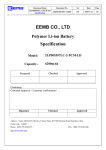
2.2.3 External Power Connector
Connect the external power supply (5 to 24 V DC ) to connector
CN1. The connector pin descriptions are given below:
CN1
+
GND
Vext
external power connector
2.3
Hardware Installation
The AX5400PA/PB board is shipped with protective electrostatic
cover. W hen unpacking, touch the board’s electrostatically
shielded packaging with the metal frame of your computer to
discharge the accumulated static electricity prior to touching the
board.
The following summarizes the installation procedures of
AX5400PA/PB.
WARNING:
8
Turn OFF the PC and all accessories connected
to the PC whenever you install or remove any
peripheral board including the AX5400PA/PB
card.
Installation
AX5400PA/PB 16 Ch. Isolated Output Card User’s Manual
2.4
Board Installation
1. Turn OFF the PC and the power connected to all
accessories.
2. Unplug all power cords and cables from the rear of the
PC.
3. Remove the PC’s cover. (Refer to your PC Operation
Guide if you are not skillful about it.)
4. Find an unused PCI expansion slot. Remove the blank
PCI expansion slot cover and save the screw for later
use.
5. Grab the upper edge of the AX5400PA/PB board. Align
the AX5400PA/PB board’s retaining bracket with the
expansion slot rear panel, and straighten the board’s
gold finger with the expansion slot. Gently push the
board into the slot.
6. Restore the screw in the PCI expansion slot retaining
bracket.
7. Replace the PC’s cover and connect the cables you
detached in step 2.
8. Now turn ON the power of the PC and other peripheral
devices. Proceed to Chapter 3 for software installation.
Installation
9
AX5400PA/PB 16 Ch. Isolated Output Card User’s Manual
This page does not contain any information.
10
AX5400PA/PB 16 Ch. Isolated Output Card User’s Manual
Chapter 3
Register Structure & Format
3.1
AX5400PA/PB I/O Address Mapping
The AX5400PA/PB uses only 1 I/O address space as follows:
3.1.1 AX5400PA
Only base address +0 is used for 16-bit wide relay output
register. This register is a read/write register for controlling
relays. The controlling bit B0 through B15 corresponds to Relay1
through Relay16 onboard.
Base address + 0
LSB
Bit No.
Bit Name
Bit No.
Bit Name
7
6
5
4
3
2
1
0
R8
R7
R6
R5
R4
R3
R2
R1
10
9
15
14
13
12
11
R16
R15
R14
R13
R12
R11 R10
8
R9
MSB
R1 - R16 represent the status of RELAY1 - RELAY16
CONTROL BIT
( R1 - R16 )
0
1
Register Structure & Format
CONTACT
CM - NO
Open
Short
CM - NC
Short
Open
11
AX5400PA/PB 16 Ch. Isolated Output Card User’s Manual
3.1.2 AX5400PB
Only base address +0 is used for 16-bit opto-isolated output
register. This register is a read/write register for digital output
control.
Base address + 0
Bit
7
6
5
4
3
2
1
0
D/O7
D/O6
D/O5
D/O4
D/O3
D/02
D/O1
D/O0
LSB
Bit
15
14
13
12
11
10
9
D/015 D/O14 D/O13 D/O12 D/O11 D/O10 D/O9
8
D/O8
MSB
D/O 0 through D/O15 represent digital output status for channel
0 through channel 15.
12
Register Structure & Format
AX5400PA/PB 16 Ch. Isolated Output Card User’s Manual
Chapter 4
Device Driver
Device driver is suitable for Plug & Play under DOS environment
to get some information from PCI BIOS. This chapter describes
in detail about how to install the device driver and use the its
command to get base address, IRQ level, and slot number. Also
testing programs are provided for reference.
After getting these information successfully, user can use the
information to act as parameter for driver function. All operations
within this section will not work if the device driver
“AX5400.SYS” is not successfully installed.
4.1
How to Install the Device Driver
Before executing any application program (including the
following examples), this device driver must be installed. To
install the device driver, type
SETUP [SOURCE DRIVE] [TARGET DRIVE] [DIRECTORY]
This will copy device driver to desire driver and directory. And
then add the following command line to your config.sys:
DEVICE = [PATH] AX5400.SYS
Example
If you insert this diskette in drive A: and want to copy the file into
C:\AX5400. You must key in the following command line at the
DOS prompt.
A:\SETUP A: C:\AX5400 [ENTER]
Then add the following line in your config.sys file.
DEVICE = C:\AX5400\AX5400.SYS
Reboot your computer.
If the AX5400 is plugged in your system, the following message
will appear:
Device Driver
13
AX5400PA/PB 16 Ch. Isolated Output Card User’s Manual
*
*
*
*
*
******************************************************************
Copyright 1998 by AXIOMTEK Co., LTD
Ver 1.0
AX5400 DEVICE DRIVER INSTALLED
******************************************************************
*
*
*
*
*
Now AX5400 acts like a file. You can OPEN, CLOSE, W RITE
(command), READ (base address, slot number) it via this device
driver.
If there is no AX5400 installed in your system, the following
message will appear:
AX5400 or PCI BIOS Not Found !!
Any OPEN to device driver will fail !
4.1.1 Using the Device Driver Command
The device driver is for user to get base address, and slot
number of AX5400 plugged in your system.
Before accessing the device driver, open it as needed. After
accessing the device driver, close it as also needed. To get any
information (BASE ADDRESS, or SLOT NUMBER), first you
must write a command to the device driver then the needed data
can be read from the device driver.
There are two commands for user to obtain base address, and
slot number. The number following the command indicates card
number.
To get base address, you must write the command string "B?" to
the device driver and then read a W ORD (two bytes) from the
device driver. This is the base address you need.
To acquire the slot number, you must write the command string
"S?" to the device driver and then read a W ORD (two bytes)
from the device driver. This is the slot number you need.
NOTE:
14
The question mark “?” must be replaced with a card
number. If base address returns to 0, it means all
information retrieved by the card number are not
available.
Device Driver
AX5400PA/PB 16 Ch. Isolated Output Card User’s Manual
Examples
1. Turbo C
*
*
*
*
*
*
*
*
#include
#include
#include
#include
#include
#include
*********************************************************
Example program for Turbo C language
To get BASE ADDRESS
SLOT NUMBER via device driver
Before executing this program, device driver must
be installed successfully.
*
*
*
*
*
*
*
********************************************************* *
<dos.h>
<stdio.h>
<string.h>
<conio.h>
<fcntl.h>
<io.h>
main()
{
int
fd;
int
base, busno;
unsigned int i, j, dat;
if ((fd=open("5400DRV",O_RDWR)) == -1 ) {
printf("AX5400 OPEN FAIL !\n");
exit(0);
}
else
printf("OK\n");
write(fd,"B1",2);
read(fd, &base,sizeof(int));
write(fd,"S1",2);
read(fd,&busno,sizeof(int));
close(fd);
printf("BASE ADDRESS :%X\n",base);
printf("SLOT NUMBER :%X\n",busno);
if (base == 0) {
printf("ERROR INFORMATION !\n");
Device Driver
15
AX5400PA/PB 16 Ch. Isolated Output Card User’s Manual
exit(0);
}
}
2. Turbo PASCAL
*
*
*
*
*
*
*
*
*********************************************************
Example program for Turbo PASCAL language
To get BASE ADDRESS
SLOT NUMBER via device driver
Before executing this program, device driver must
be installed successfully
*
*
*
*
*
*
*
********************************************************* *
PROGRAM TP_DEMO(input,output);
uses dos,crt;
var
fdw:text;
fdr :file of integer;
addr,irqno,slotno:intrger;
begin
clrscr;
assign(fdw,'5400DRV');
assign(fdr,'5400DRV');
rewrite(fdw);
writeln(fdw,'b1');
reset(fdr);
read(fdr,addr);
rewrite(fdw);
writeln(fdw,'s1');
reset(fdr);
read(fdr,slotno);
close(fdr );
writeln('BASE ADDRESS : ',addr:10);
writeln('SLOT NUMBER :',slotno:10);
if addr <> 0 then writeln('The information are correct');
END.
16
Device Driver
AX5400PA/PB 16 Ch. Isolated Output Card User’s Manual
3. Qbasic 4.5
*
*
*
*
*
*
*
*
*********************************************************
Example program for QB45 language
To get BASE ADDRESS
SLOT NUMBER via device driver
Before executing this program, device driver must
be installed successfully.
*
**
**
**
********************************************************* *
OPEN "5400DRV" FOR OUTPUT AS #1
OPEN "5400DRV" FOR BINARY AS #2
PRINT #1, "B1"
GET #2, 1, BL%
GET #2, 1, BH%
PRINT #1, "S1"
GET #2, , S%
CLOSE #1
CLOSE #2
BL = BL%
BH = BH%
ADDR = BH * 256 + BL
PRINT "BASE ADDRESS: ", ADDR
PRINT "SLOT NUMBER : ",S%
IF ADDR <> 0 THEN PRINT " The information are correct"
Device Driver
17
AX5400PA/PB 16 Ch. Isolated Output Card User’s Manual
This page does not contain any information.
18
AX5400PA/PB 16 Ch. Isolated Output Card User’s Manual
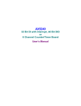
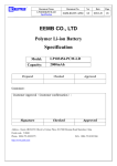
Appendix A
Block Diagram
VCC
CM 0
NC 0
D/O 0
Output
Register
with
Readback
opto coupler
and limit
resister ckt
NO 0
(RELAY1)
D/O 1
VCC
D/O 15
CM 1
P
NC 1
C
opto coupler
resister ckt
NO 1
(RELAY2)
I
B
U
S
PCI
Bridge
VCC
.
.
.
.
.
.
.
.
. CM 15
NC 15
opto coupler
resister ckt
NO 15
(RELAY16)
Block Diagram
19
AX5400PA/PB 16 Ch. Isolated Output Card User’s Manual
This page does not contain any information.
20
+
-
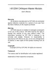
Location Diagram
CN2
CN1
1
J23 J24
RELAY 4
for
AX5400PA
RELAY 2
for
AX5400PA
J7 J8
RELAY 3
for
AX5400PA
RELAY 1
for
AX5400PA
RELAY 6
for
AX5400PA
RELAY 5
for
AX5400PA
RELAY 8
for
AX5400PA
RELAY 7
for
AX5400PA
RELAY 10
for
AX5400PA
RELAY 9
for
AX5400PA
RELAY 14
for
AX5400PA
RELAY 13
for
AX5400PA
J55 J56
RELAY 12
for
AX5400PA
RELAY 11
for
AX5400PA
RELAY 16
for
AX5400PA
RELAY 15
for
AX5400PA
AX5400PA/PB 16 Ch. Isolated Output Card User’s Manual
Appendix B
Location Diagram
21
AX5400PA/PB 16 Ch. Isolated Output Card User’s Manual
This page does not contain any information.
22
AX5400PA/PB 16 Ch. Isolated Output Card User’s Manual
Appendix C
Functional Description
Relay Outputs
The sixteen onboard electromechanical relays are Form C relays.
The contact rating is 3A at 120V AC or 24V DC .
Form C Relay
Each Form C relay has three contacts: Normally Open (NO),
Common (CM) and Normally Closed (NC). The CM post, located
at the middle, can make contact with either NO post or NC post.
W hen the control bit at relay output register is low (0), the CM
post and NC post make contact. If the control bit is high (1), the
CM post and NO post make contact. The following table lists the
contact arrangement for Form C relay.
CONTROL BIT
( RO1 ~ RO16 )
0
1
NOTE:
CONTACT
CM - NO
Open
Short
CM - NC
Short
Open
Upon power up or reset, the CM and NC contacts
are connected.
Logic "0"
COM
Logic "1"
NC
NO
Functional Description
COM
NC
NO
23
AX5400PA/PB 16 Ch. Isolated Output Card User’s Manual
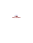
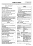
Open-Collector Output
Open-Collector output can be used to control another device
having larger current (100mA/channel) or voltage levels (5 to
24VDC). Limit resistor for the AX5400 includes 16 independent
0Ω (default) resistor, that is one resistor for each output channel.
The list of output channel and its corresponding limit resistor is
given in below table.
The sink current calculation is
Io =
VEXT - VCE (sat)
RL
There VEXT = external power supply voltage from 5 to 24VDC,
VCE (sat) = transistor collector-emitter saturation voltage ≅ 0.7V
and R L = limit resistor.
Here is an example for calculating R L , refer to below figure.
Assume an LED’s Load is 24mA and external power voltage is
5V then according to the above formula:
RL =
5V - 0.7V
= 179Ω
24mA
So install 179Ω resistor onto onboard reserved space.
VEXT (5V)
+5V
=179Ω
RL~
Io
VEXT(5V)
D/Ox~
Io=24mA
PC817
LED
1/7
D/O x+
ULN2803
From output
register
1/8
74LS244
NOTE:
24
D/Ox+
D/OxRL
VEXT
D/O0+ through D/O15 + pin at CN2
D/O0- through D/O15 pins at CN2
Onboard R1-R8 and R13-R20
External power supply voltage connected to
the AX5400 via pin1 and pin2 of CN2 or CN1
Functional Description