1
D811627 00100_02
INSTALLATION MANUAL
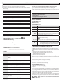
2) GENERAL INFORMATION
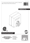
Actuator for motorizing residential and industrial sectional doors.
Its compact design and mounting versatility mean the drive can be applied in
different ways.
3) TECHNICAL SPECIFICATIONS
Power supply:
230V ±10%, 50/60Hz (*)
Max. power input:
70W
Limit switch:
Electronic ENCODER model
Output shaft MAX. 18 rpm
Courtesy light:
24V bulb ~ max. 25W, E14
Operating temperature range:
-15°C / +55°C
Max. door size:
20 m2
Max. torque:
55 Nm
Lubrication:
Lifetime greased
Knob-operated mechanical release
Protection rating:
IP 40
Noise level:
<70dBA
Operator weight:
10 kg
Dimensions:
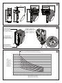
See Fig. H
Accessories power supply:
24V~ (180 mA)
24V max 25W
Fuses:
See Fig. D
Built-in Rolling-Code radio-receiver:
frequency 433.92MHz
8) ADJUSTMENTS
RECOMMENDED ADJUSTMENT SEQUENCE:
Adjusting the limit switches (Fig. E)
Autoset (Fig. F)
Programming remote controls (Fig. G)
Setting of parameters/logic, where necessary
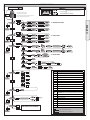
8.1) PARAMETERS MENU (N?P?K)
(TABLE “A” PARAMETERS)
Manual operation:
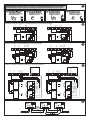
Flashing light connection:
7.1) SAFETY DEVICES
Note: only use receiving safety devices with free changeover contact.
Fig. L:
Connection of 1 untested device (photocell or safety edge).
Fig. M: Connection of 1 tested device (photocell or safety edge).
Fig. N: Connection of 2 tested devices (photocells or safety edges). This connection is made possible via the SCS-IO optional module only.
8.2) LOGIC MENU (JMEGA)
(TABLE “B” LOGIC)
8.3) RADIO MENU (0"'-)
Logic
?BBQR?PR
Add 2ch Key
associates the desired key with the 2nd radio channel command
PC?B
Read
Checks a key of a receiver and, if memorized, returns the
number of the receiver in the memory location (from 01 to
64) and number of the key (T1-T2-T3 or T4).
CP?QC
Erase List
WARNING! Erases all memorized remote controls from
the receiver’s memory.
AMB06
Read receiver code
Displays receiver code required for cloning remote controls.
SI
ON = Enables remote programming of cards via a previously memorizedW LINK transmitter. It remains enabled for 3 minutes
from the time the W LINK remote control is last pressed.
OFF=W LINK programming disabled.
.
4) REMOVING THE COVER Fig. A
5) TUBE ARRANGEMENT Fig. B
6) INSTALLING THE OPERATOR Fig. C
5) CABLE ENTRY FIG. I
6) MANUAL RELEASE (See USER GUIDE -FIG. Y-).
---------------------------------------------------------7) WIRING
TERMINAL
DESCRIPTION
JP2
Transformer wiring
JP10
Motor wiring
1-2
Antenna input for built-in radio-receiver board (1:BRAIDING 2:
SIGNAL)
3-4
START/OPEN INPUT (N.O.)
3-5
STOP input (N.C.) If not used, leave jumper inserted
3-6
PHOTOCELL input (N.C.) If not used, leave jumper inserted
3-7
SAFETY EDGE input (N.C.) If not used, leave jumper inserted
8-9
24 V~ output for flashing light (max. 25 W)
10-11
24V~ max. 180mA output - power supply to photocells or other devices.
12-13
24V~ Vsafe max. 180mA output - power supply to transmitters
photocells with test.
14-15
(NO contact) / Output 1 height programmable
16-17
PARTIAL OPENING/CLOSE input (N.O.)
1-2 (SCS-IO)
PHOT-FAULT input (NO). Input for photocells equipped with NO
test contact.
1-3 (SCS-IO)
BAR-FAULT input (NO). Input for safety edges equipped with NO
test contact.
4-5 (SCS-IO)
(NO contact) / Output 2 Height programmable
6-7 (SCS-IO)
Gate open light/2nd radio channel output (NO contact)
Add Start Key
associates the desired key with the Start command
?BBAF
(*) Special supply voltages to order.
Usable transmitter versions:
All ROLLING CODE transmitters compatible with
Description
-
IMPORTANT NOTE: THE FIRST TRANSMITTER MEMORIZED MUST BE
IDENTIFIED BY ATTACHING THE KEY LABEL (MASTER).
In the event of manual programming, the first transmitter assigns the RECEIVER’S
KEY CODE: this code is required to subsequently clone the radio transmitters.
The Clonix built-in on-board receiver also has a number of important advanced
features:
t $MPOJOHPGNBTUFSUSBOTNJUUFSSPMMJOHDPEFPSöYFEDPEF
t $MPOJOHUPSFQMBDFUSBOTNJUUFSTBMSFBEZFOUFSFEJOSFDFJWFS
t 5SBOTNJUUFSEBUBCBTFNBOBHFNFOU
t 3FDFJWFSDPNNVOJUZNBOBHFNFOU
To use these advanced features, refer to the universal handheld programmer’s
instructions and to the CLONIX Programming Guide, which come with the universal handheld programmer device.
8.4) LANGUAGE MENU (J?LES?EC)
Used to set the programmer’s language on the display.
8.5) DEFAULT MENU (BCD?SJR)
Restores the controller’s default factory settings.
8.6) AUTOSET MENU (SRMQCR) (Fig. F)
t .PWFUIFEPPSUPUIFDMPTFEQPTJUJPO
t -BVODIBOBVUPTFUPQFSBUJPOCZHPJOHUPUIFSFMFWBOUNFOVPOUIF7&/&3&
D panel.
t "TTPPOBTZPVQSFTTUIF0,CVUUPOUIFiwNFTTBHFJTEJTQMBZFEBOE
the control unit commands the door to perform a full cycle (opening followed
by closing), during which the minimum torque value required for the door to
move is set automatically.
During this stage, it is important to avoid breaking the photocells’ beams and
not to use the START and STOP commands or the display.
Once this operation is complete, the control unit will have automatically set
the optimum torque values. Check them and, where necessary, edit them as
described in the programming section.
WARNING: Check that the force of impact measured at the points
provided for by standard EN 12445 is lower than the value laid down
by standard EN 12453.
ARGO -
15