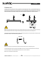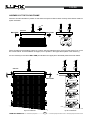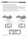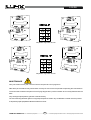
1
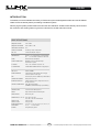
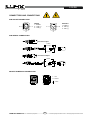
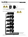
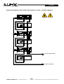
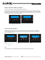
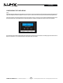
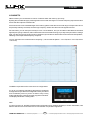
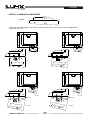
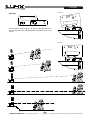
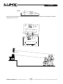
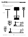
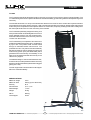
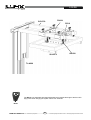
LX-F6
LX-F6P
USER MANUAL
V.13.10
Lynx Pro audio S.L.
Valencia, Spain - www.lynxproaudio.com - [email protected]
LX-F6
Class D Powered (bi-amplified)
Integrated Digital Processing
Internal temperature control
Electronic protection
Digital inclinometer system
High quality components
Online monitoring available
LYNX Pro Audio S.L. - Valencia, Spain -
www.lynxproaudio.com - [email protected]
LX-F6 / LX-F6P line array cabinet
Manufacturer
LYNX Pro Audio S.L.
Calle 7 - Pol. Ind. Picassent
E-46220 Picassent (Valencia)
CB SCHEME, IEC SYSTEM FOR CONFORMITY TESTING AND CERTIFICATION
OF ELECTRICAL EQUIPMENT
CE CERTIFICACTION, EUROPEAN PRODUCT
This user manual is property of Lynx Pro Audio S.L. Any reproduction of this manual, by any means is strictly prohibited.
Copyright 2013. All rights reserved.
CONTENTS
- SAFETY PRECAUTIONS
5
- CABINET INTRO
SPECIFICATIONS
6
BACK PANEL
7
CONNECTORS AND CONNECTIONS
8
- CONFIGURING THE CABINET DSP OPTIONS
CONFIGURING THE CABINET DSP OPTIONS
9
CONFIGURATION PANEL
9
SELECT THE INPUT: DIGITAL / ANALOG
12
SELECT AND RUN PRESETS
10
CONFIGURING THE LINE ARRAY
11
N CABINETS
11
AIR ABSORTION COMPENSATION
13
THROW
13
MANUAL AND AUTOMATIC MODES
14
ONLINE CONTROL SYSTEM
15
CONFIGURING ETHERNET
16
- SOFTWARE RAINBOW
22
- ACCESSORIES
24
- LYNX F6 FLYING SYSTEM
INTRO
25
TECHNICAL DATA
27
SAFETY PRECAUTIONS
28
HOW TO USE THE FLYING FRAME
29
ASSEMBLY AND ANGULATION OF THE CABINETS
31
MAINTENANCE
32
INSTALL & RIGGING ACCESSORIES
35
- GUARANTEE
41
LX-F6
Before starting to use this device, please read this instruction manual carefully.
Keep these instructions in the place where the equipment will be used and with easy access to them.
- Electrical appliance.
The exclamation mark within a triangle identifies the presence of electricity. Use the system carefully
without wet hands or feet. Avoid installing the speaker in wet or excesivelly humid places. Regularly
check the condition of the cables and make sure these are not being walked on or pinched. Connect
the speaker to bipolar, earthed mains. The mains plug must be connected to the appropriate protection
(fuse or breaker). Connection to any other type of mains could result in an electrical shock and violate
local electrical codes. DO NOT CONNECT OR DISCONNECT THE AC POWER CONNECTORS
UNDER LOAD.
- Heavy equipment.
Apply back protection when using the system. Avoid loading and unloading at heights.
- Electrical shock risk.
The diagonal mark within a triangle identifies the presence of dangerous voltage.
Do not open or handle the interior of the box. These parts are not to be adjusted by the user. For
maintenance and/or repair please go to an authorized service centre.
In order to reduce the risk of electric shock, disconnect from AC before plug in or unplugging Audio
signal cables. Reconnect to AC only if all signal connections are made and secured.
Never manipulate the ground type plug provided.
The AC mains plugs should always remain accessible for operation.
Unplug the loudspeaker during storms or when it’s being used for a long time.
- Hearing damage risk.
These systems can reproduce large quantities of sound pressure which can damage hearing. Take
precautions if you are going to be near them for extended amounts of time and do not get too close.
- Hanging – Flying.
Do not hang the cabinets from the handles or from any other part other than the designated hanging
point. When flying this system please observe the technical and “Lynx On Stage” software data
carefully. Never exceed the maximum safe working loads or ignore the instructions included within this
manual. Use Only flying accessories provided by Lynx Pro Audio S.L.
Rigging must be always carried out by professionals.
- Delicate Material.
Please ensure no foreign object or water enters the speaker. Do not place material that contains liquid
on or near the unit. Only clean the unit with dry cloths. Do not use solvents.
-Overheating – Fire risk.
To reduce the risk of the speaker over heating, avoid direct contact with sunlight. Avoid placing the unit
close to heat inducing objects such as radiators. Do not cover the equipment in use and do not block
any ventilation openings. Do not put naked flame, such as lighted candles, close or on top of the unit.
- Electromagnetic and interferente emissions.
Avoid placing objects which through electromagnetic waves can damage the unit, such as mobile
phones, lap tops, magnetic strip cards etc.
This system complies with normatives
EN 55103-1 (1)
EN 55103-2 (2)
(1) This device may not cause harmful interferences.
(2) This device may receive interference including interferences that may cause undesired working.
-IMPORTANT NOTE.
This Equipment must be used in accordance with these instructions and by trained professional
personnel only.
This equipment should not be used in places with extreme tropical climates. Don’t expose this
apparatus to extreme humidity and or temperature values.
5
LYNX Pro Audio S.L. - Valencia, Spain -
www.lynxproaudio.com - [email protected]
LX-F6
INTRODUCTION
To facilitate, correct and reliable use of the Lynx F6 Line Array we have designed this instruction manual. Please
read the manual carefully before proceeding to install the system.
When flying this system please observe the technical and “Rainbow” software data carefully. Never exceed
the maximum safe working loads or ignore the instructions included within this manual.
SPECIFICATIONS:
FREQUENCY RANGE
75Hz -20KHz
FREQUENCY RESPONSE
90Hz- 18KHz ± 3dB
HORIZONTAL COVERAGE
100º
VERTICAL COVERAGE
According to Array configuration
MAX SPL
124 dB/ 127dB peak 1w@ 1m
TRANSDUCERS
LF/MF: 2 x 6" Custom Nomex Cone Neodimium
HF:
1 x 5" Air Motion Transformer with horn
SHAPE
Bass Reflex Direct Radiation
SIGNAL CONNECTION
NEUTRIK connectors XLR Male Input
XLR Female Loop Thru
AC POWER
230v / 115v selectable. 50/60 Hz 3A
AC CONECTIONS
16A NEUTRIK POWERCON with Looping Output
ONLY LX-F6
ACTIVE CABINET
POWER AMPLIFIER
1500W Class D with Switching Power supply
1000W Low/Mid + 500W High
DSP
Internal Lynx processor DSPB-22® with FIR filters
CABINET ADJUSTMENT
Back panel LCD screen
INTERNAL CONTROLS
Cabinet Angle detection / Temperature sensor /
Fan Speed control
CONTROL CONNECTIONS
USB (DSP programming),
ETHERNET* (Online Monitoring System OMS®)
CONSTRUCTION
15 mm Premium Birch plywood
FINISH
High resistant water-based black paint
FRONT DESIGN
Black steel grille
DIMENSIONS (H x W x D) 204 x 646 x 290 mm
204 x 687 x 290 mm with ball-pins
WEIGHT LX-F6
WEIGHT LX-F6P
23 Kg (50 lbs)
20 Kg (44 lbs)
INTERCABINET ANGLE
ADJUSTMENT
0º/ 0,5º/ 1º/ 1,5º/ 2º/ 2,5º/ 3º/ 4º/ 5º/ 6º / 7º
8º / 9º
+ 7º Front adjust
RIGGING
Integrated flying plates
6
LYNX Pro Audio S.L. - Valencia, Spain -
www.lynxproaudio.com - [email protected]
LX-F6
LX-F6 BACK PANEL
6
5
8
4
3
2
7
1
1.- SIGNAL INPUT.
2.- SIGNAL LINK.
3.- AC INPUT.
4.- AC LINK (max. +2 cabinets).
5.- USB.
6.- DSP CONTROL.
7.- SPK LINK OUT.
8.- ETHERNET OPTION
LX-F6P BACK PANEL
2
1
1.- SPK LINK IN.
2.- SPK LINK OUT.
This passive cabinet includes exactly the same components as the active version, but without the amplification.
By linking this passive cabinet as «a slave» to an active one it takes the active features including the corrections
applied from the DSPB22 and the inclinometer and takes the amplification and processing from the active version.
It obtains the frequency response correction by air absorption, phase adjustments, amplitude, Cross over filters and
RMS and peak double limitation.
By linking the cabinets in this way (1 passive + 1 active), the system delivers exactly the same power as if all cabinets
were active but with the linking option it considerably reduces the weight and the cost of the system.
7
LYNX Pro Audio S.L. - Valencia, Spain -
www.lynxproaudio.com - [email protected]
LX-F6
CONNECTORS AND CONNECTIONS
XLR SOCKET CONNECTORS
2
1
INPUTS
1.- EARTH
2.- LIVE (+)
3.- LIVE (-)
1
2
OUTPUTS
1.- EARTH
2.- LIVE (+)
3.- LIVE (-)
3
3
XLR AEREAL CONNECTORS
Connect to input
1 Earth
2 Live(+)
3 Live(-)
Connect to output
1 Earth
2 Live(+)
3 Live(-)
SOCKET POWERCON CONNECTORS
L - Line
N - Neutral
- Earth
8
LYNX Pro Audio S.L. - Valencia, Spain -
www.lynxproaudio.com - [email protected]
LX-F6
SOCKET POWERCON CONNECTORS
L - Line
N - Neutral
- Earth
- CAUTION: DO NOT CONNECT OR DISCONNECT THE AC POWER CONNECTORS
UNDER LOAD.
ACTIVE SYSTEM CONNECTION EXAMPLE (6 CABINETS)
LX-F6
LX-F6
LX-F6
LX-F6
LX-F6
LX-F6
Connect to signal output
Connect to AC output
9
LYNX Pro Audio S.L. - Valencia, Spain -
www.lynxproaudio.com - [email protected]
LX-F6
MIXED ACTIVE/PASIVE SYSTEM CONNECTION EXAMPLE (3 ACTIVE + 3 PASSIVE CABINETS)
LX-F6
LX-F6P
LX-F6
LX-F6P
LX-F6
Connect to signal output
LX-F6P
Connect to AC output
10
LYNX Pro Audio S.L. - Valencia, Spain -
www.lynxproaudio.com - [email protected]
LX-F6
Note: Finite Impulse Response (FIR) filters are used in the signal processing of the LX-V8 cabinet. FIR is a type of
digital filter with linear phase characteristics. This frees system designers from the constraints of phase anomalies
associated with analogue filters or their digital versions (IIR, Infinite Impulse Response). When properly used, FIR
filtering can audibly improve a system’s impulse response and reduce crossover interference.
CONFIGURING THE CABINET DSP OPTIONS.
From the buttons below the display on the Lynx cabinet’s back panel you are able to configure the Basic
adjustment functions of the internal DSP.
NOTE:You must apply the desired configuration in each cabinet. This is done via the buttons located on the back
panel of the cabinet and requires electrical power to work.
From the LX cabinet’s back panel you are able to configure 4 basic internal DSP adjustments:
- Number of cabinets in the array to apply shelving equalization for frequency response correction.
- Air absorption compensation at various “throw” distances.
- Enable or disable the Inclinometer.
- Enable or disable the automatic correction feature.
CONFIGURATION PANEL
On the back panel you will see 3 buttons and an information screen, on which you can read the established parameters
and information such as digital or analog input, amplification module temperature, input signal level and name of the
current preset (Fig1). If changes are not made the display will automatically dim to save energy and avoid unnecessary
light in situations where light is not wanted. To re-activate the light simply press the OK button.
Fig 1
LYNX Pro Audio S.L. - Valencia, Spain -
11
www.lynxproaudio.com - [email protected]
LX-F6
SELECT THE INPUT: DIGITAL OR ANALOG
There are four input options: Analog / Digital L / Digital R / Digital L+R
To select the input mode just press the OK button (3) and the up button (1), both at the same time but pressing
the OK button first. Then you can select one of the four options using the up button (1). To confirm your selection
press OK (3) until the progress bar finishes. The display will show an inverted D (digital) or an inverted A (Analog)
so you can always know if the input is digital or analog.
1
2
3
SELECT AND RUN PRESETS
To change the preset configuration just press the up button (1) and down button (2) until you see the title and
preset number required (Fig2). Once found, press OK (3) until the progress bar finishes (Fig3). The display will
indicate “Loading DSP” (Fig4)
Fig 2
Fig 3
Fig 4
Note:
In case of a power cut, the DSP will save its last configuration when restarted.
12
LYNX Pro Audio S.L. - Valencia, Spain -
www.lynxproaudio.com - [email protected]
LX-F6
CONFIGURING THE LINE ARRAY.
Note:
You must apply the desired configuration in each cabinet. This is done via the buttons located on the back panel of the
cabinet and requires electrical power to work. For your comfort, we recommend you do this before flying the array.
On the back panel you will see 3 buttons and an information screen, on which you can read the established parameters
and information such as amplification module temperature, cabinet inclination and name of the current preset.
If changes are not made the display will automatically dim to save energy and avoid unnecessary light in situations where
light is not wanted. To re-activate the light simply press the OK button.
13
LYNX Pro Audio S.L. - Valencia, Spain -
www.lynxproaudio.com - [email protected]
LX-F6
N CABINETS.
With this button you can select the number of cabinets which will make up your array.
By doing this, the DSP will apply a shelving filter in the low and mid range to correct the frequency response and thus
ensure that the response maintains flat.
It is known that one of the disadvantages of a line array system is that the low and mid range of frequencies cannot
be precisely vertically corrected, whereas high frequency drivers have their own waveguide to do this.
For this reason, you can set up a line array to cover “x” area distance, and you can obtain a directed and controlled
high frequency range. However, it will not be the same on the mid and low range, if you stay at one point of the coverage
area, you will hear one of the high frequency drivers but you will also be able to listen to the whole low mid speakers,
obtaining a decompensated frequency response.
You can see this on the measurements comparing 1,4 and 8 cabinets (Black = 1x LX-F6, Red = 4x LX-F6, Green
= 8x LX-F6)
The DSP incorporates 5 of the most common configurations:
4, 6, 8, 10 or 12 cabinets, maintaining the preset of 12 cabinets
for larger size arrays. Select the configuration which you believe
to be acoustically correct. If you do not wish to carry out any
further adjustments, press OK until the progress bar finishes.
The display will indicate “Loading DSP”.
Note:
In case of a power cut, the DSP will save its last configuration when restarted. However, if it was in Auto Mode, it will
take the data from the inclinometer and re-calculate the compensation algorithms.
14
LYNX Pro Audio S.L. - Valencia, Spain -
www.lynxproaudio.com - [email protected]
LX-F6
AIR ABSORPTION COMPENSATION
As sound travels over distance, it starts to lose its energy due to atmosphere and physical properties. This varies
according to factors such as relative humidity and temperature and is most appreciable with high frequencies. To
compensate for this loss the Lynx LX cabinets apply special equalization algorithms. This compensation is carried
out for 3 types of throw: Short, Mid and Long.
THROW
After selecting the number of cabinets, the second button enables you to change the configuration of the throw as
follows:
- Short throw (Black)
- Mid throw (Red)
- Long throw (Green)
- Manual (with no correction)
- Auto (Reads the inclinometer reading and depending on the cabinet’s inclination this mode will apply the appropriate
parameter) Note: This data is only taken on DSP Start up to avoid unexpected equalization changes caused by
unnecessary movement of the array. This means that once the cabinets have their final inclination (the array must be
lifted, not stacked on the stage) you have to restart the preset in order to apply the necessary EQ for the real inclination
of each cabinet. Then you can lift the array completely.
To manual setup from the back panel, separate the coverage area in 3 smaller zones, one closet o the array, one in
the middle and one further away trying to ensure they are similar in size. Depending on the size of the array and its
angulation you can add or remove cabinets to each zone. Once this is done, enter the type of throw in to each cabinet
bearing in mind which area they are targeting.
15
LYNX Pro Audio S.L. - Valencia, Spain -
www.lynxproaudio.com - [email protected]
LX-F6
With classic configurations, the higher cabinets have the task of covering the area furthest away, thus needing the
“Long Throw” preset. Remember you must enter this preset in to every cabinet that requires this configuration.
Choose the configuration which meets the needs of your installation. If you do not need to make any further changes
press OK until the progress bar finishes. The display will indicate “Loading DSP”.
MANUAL MODE
By selecting Manual mode, the system does not take in to account the number of boxes or the inclination, and uses
the factory equalization parameters, crossover and dynamics. This enables you to manually correct the system with
an external processor if the configuration is not common or you desire a different type of adjustment other than that
supplied by the factory.
AUTOMATIC MODE
In this mode the cabinet will read the inclinometer information upon Start up and then apply the corresponding preset
according to the inclination of the cabinet. This only happens when the cabinet is switched on and will last until the
next reading which will be when the power is taken up again. This is done to anticipate movements such as wind
causing variations of the inclination and changing the configuration when not desired.
Average values have been taken to detect the angulation and apply different throw presets based on the most typical
configurations:
- If the cabinet has between
0º and –13º
The Long Throw preset will be applied.
- If the cabinet has between
–13,1º and –21º The Mid Throw preset will be applied.
- If the cabinet has between
–21,1º and –90º The Short Throw preset will be applied.
Note: If positive degree values are detected, the DSP Long Throw preset will be applied.
16
LYNX Pro Audio S.L. - Valencia, Spain -
www.lynxproaudio.com - [email protected]
LX-F6
ONLINE CONTROL SYSTEM
Who is it for?
Users of Self powered DSP incorporated Lynx Pro Audio Cabinets where the user has requested the cabinets be
supplied with the Ethernet Module kit.
What is it for?
Obtain detailed information of cabinet behaviour and monitor the cabinet/s in real time. You can change the
preset, gain, mute and polarity. You can also activate the air absorption compensation and select the «SOLO»
mode.
How does it work?
Via Ethernet (cable or wireless). Once installed, the O.C.S. software automatically detects all the cabinets
connected to the network and displays them in the O.C.S. window on the users PC.
What does it show?
As well as displaying the cabinet model and IP address the O.C.S will be monitoring in real time and the user will
be able to view RMS levels, Input clip, power module temperature, compression levels, air absorption
compensation and cabinet angulation.
17
LYNX Pro Audio S.L. - Valencia, Spain -
www.lynxproaudio.com - [email protected]
LX-F6
CONFIGURING ETHERNET TO WORK WITH THE LYNX F6
There are two possible ways to connect:
1.- Connecting through an ETHERNET SWITCH/HUB::
- You will need a normal CAT5 Cable.
2.- Connecting through a Wirless ETHERNET.
Let us now proceed to configure the Ethernet network, setting the IP address of the computer as static. To do this
go to:
START > CONFIGURATION > NETWORK CONFIGURATION
We will launch the properties of "Local Area
Connection" by clicking the right mouse button
and clicking on properties.
18
LYNX Pro Audio S.L. - Valencia, Spain -
www.lynxproaudio.com - [email protected]
LX-F6
Select "Internet Protocol (TCP / IP)" and click on
properties.
Select: “Use next IP Address” And write as you wish, in
order to configure your network.
Normally, Ip values will be something like this:
IP Address: 192.168.1.xxx
Subnet Mask: 255.255.255.0
Where xxx will be a number between 1 and 254
Accept to quit the network settings and again to apply
them at the next screen. Depending on the Windows Version, you will be asked to reboot or not.
Once the Computer is configured with a static IP proceed
to connect to the line array system through the OCS (online
control system) software.
Open the OCS software and from the Initial Screen choose
Ethernet device into the configuration menu.
It will open a different screen, as follows, there you can see your Network configuration, and the cabinets currently
connected.
LYNX Pro Audio S.L. - Valencia, Spain -
19
www.lynxproaudio.com - [email protected]
LX-F6
If you want to change the IP select the cabinet and modify the assigned IP in order to be able to connect to it.
By default, the Cabinet will have this IP 192.168.1.100
The Network enviroment consists in the first 3 sets of three numbers separated by dots. In order to detect/communicate
with the cabinets, the software and the cabinets must have the same Network settings.
If it is not in the same environment Windows Profesional (2000, XP, VISTA, Windows 7 and 8) will detect it, but is not
going to be able to establish connection. In Windows Home, the processor is not going to be detected until the same
enviroment is applied.
In order to change the IP settings to have the same configuration as the PC, we can change the IP address of the
cabinets by clicking in the Assign IP to select Device button after writing in the box above the desired data. Remember
there cannot be two devices with exactly the same IP address, the last set of three numbers has to be different and
unique to each one of the devices.
20
LYNX Pro Audio S.L. - Valencia, Spain -
www.lynxproaudio.com - [email protected]
LX-F6
for example, write 192.168.1.100 and click "Change Device IP" button.
The OMS software will send the new IP to the cabinet and it will scan the network again showing the same information
as before, plus more information such as Pc name, IP address and Port in which the communication is established.
When we have a lot of cabinets connected in the network we can use the button “Identify Device” to see which
box is selected (two activity LEDS will blink for one second). With that information then we can “Change device
NAME” assigned to this Cabinet by clicking in the “Change Device Name” button after writing in the box above the
desired Name.
Returning to the main screen, we can see each cabinet showing: Model, IP address and Name, as well as monitoring:
RMS levels, Input clip, power module temperature, compression levels, air absorption compensation and cabinet
angulation, as well as displaying the cabinet model and IP address.
21
LYNX Pro Audio S.L. - Valencia, Spain -
www.lynxproaudio.com - [email protected]
LX-F6
If you need to know the PC Network settings go to:
START > ALL PROGRAMS > ACCESSORIES > Command Prompt
It will open the cmd.exe from where you can type the IPCONFIG command ( ipconfig + Enter),
which will show your actual IP settings.
Here we can see that this PC has IP set as 192.168.2.99.
22
LYNX Pro Audio S.L. - Valencia, Spain -
www.lynxproaudio.com - [email protected]
LX-F6
You can also use the command promt to know if an IP is already in use by another device. In this case type "ping
IP" (ping 192.168.2.xxx) and press enter. If there is no device with this IP you will see the following information:
If the IP is in use, the device will respond to the Ping, and we will obtain this information:
You now have the Cabinets working in the ETHERNET Network Enviroment.
23
LYNX Pro Audio S.L. - Valencia, Spain -
www.lynxproaudio.com - [email protected]
LX-F6
RAINBOW – ACOUSTICAL PREDICTION SOFTWARE
Thanks to the RAINBOW software, you will be able to “virtually” determine the acoustical response of one or
various cabinets at the same time.
Based on polar response measurements, taken
meticulously with a 360º coverage both vertically
and horizontally, the Rainbow software is able to
calculate the SPL response including the
interaction between them taking into account the
magnitude and phase response, in order to
enable the user to correct cancellations and even
to create them if the acoustical design so
requires.
Rainbow is very easy to use and offers a very
intuitive design, multitool interface and on-line
updatable data base.
The Rainbow software has been designed by and
for sound technicians. Its aim is to help installers
and users of LYNX products.
This software is able to import WMF Vector Files
with technical drawings and insert them directly
into the prediction window and thus enabling real
measurement predictions.
This also helps to determine dead zones and
obtain the maximum performance from each of
the cabinets installed.
24
LYNX Pro Audio S.L. - Valencia, Spain -
www.lynxproaudio.com - [email protected]
LX-F6
Features
The RAINBOW acoustical prediction software allows among other things:
- Prediction up to 4 LINE ARRAYS of 24 cabinets each simultaneously, together with multiple points
with cabinets
- Flying points information according to the inclination of the cabinets
- Weight calculation of the different systems
- Sub-bass simulation (for instance to achieve cardiod configurations)
- Orientation of cabinets (Horizontal/vertical)
- Throw Direction of cabinets (right/ left)
- Individual delay per cabinet/system
- Polarity selection for each cabinet
- Up to 40 process insertions with Equalization and CrossOver assignable per cabinet.
- Simulation of the Air absorption sound loss with the distance
- SPL Pressure information
- Distance measurement
- Import of CAD files
- Up to 4 audience or hearing zones
- Coverage curves on the hearing zones.
- Export of SPL Map and coverage curves on jpg or bmp format
- Print project report (SPL prediction, flying points, weights, cabinet inclination, polarities, process
aplied, EQ Curves…)
25
LYNX Pro Audio S.L. - Valencia, Spain -
www.lynxproaudio.com - [email protected]
LX-F6
ACCESSORIES
The Lynx F6 system has at its disposal a variety of practical accessories to help use the system in a number of
applications.
SV-LXV6
SV-LX212S
Flying frame for rigging of
up to 36 cabinets
Flying frame for the sub
bass cabinet.
The LX-F6 can then be
flown underneath the sub
GS-0,8
SS-LXF6
Steel shackle 800 Kg
Ground stack support
SP-TLF6
SA-F6
Adjustable T-bar support
for LX-F6 with sub unit.
Pole is included
Accessory for negative
angulation
FC-LXF6
Flight case for 4 LX-F6
FD-1LXF6NL
Rain cover for the back
panel of the cabiinet
FC-LX212/F6
Flight case for 4 LX-F6 +
1 Sub LX-212
SA-LX212
SA-212
Accessory for negative
angulation
Adaptor use to fly the
LX-F6 under the sub units
LX-212S
26
LYNX Pro Audio S.L. - Valencia, Spain -
www.lynxproaudio.com - [email protected]
LX-F6
LYNX F6 FLYING SYSTEM
SVLX-F6
Cabinet 1
Cabinet 2
Cabinet 3
Cabinet 4
Cabinet 5
Cabinet 6
Cabinet 7
Cabinet 8
Cabinet 8
Up to 24 cabinets
27
LYNX Pro Audio S.L. - Valencia, Spain -
www.lynxproaudio.com - [email protected]
LX-F6
For a correct and safe Flying Frame usage for the Lynx LX Line Array we have created this instruction manual.
Read this manual carefully before flying your Lynx system. Observe technical data, “Rainbow” software data and do
not exceed maximum load capacities and usage conditions indicated in this manual.
All our products are put through rigorous tests and quality controls. We guarantee the characteristics described
here within and their quality against any fabrication defect.
The user loses all rights, if any modification to the product is carried out, over exceeding the loading capacities or
does not correctly install the system using all the pins in their correct positions.
SV-LXF6
The system is equipped with a solid and precise flying system that can hold up to 24 cabinets.
The flying support SV-LXF6 allows you to hang the array and adjust its inclination.
The Rainbow software provides all the necessary information to mount the array cabinets with the required angles
to get the calculated coverage and pressure. The Lynx is a practical equipment easy to install in any event.
28
LYNX Pro Audio S.L. - Valencia, Spain -
www.lynxproaudio.com - [email protected]
LX-F6
TECHNICAL DATA
The flying frame for the LYNX Line Array is compised of an upper support (SV-LXF6), constructed with steel and on
which all acoustic cabinets are hung, one beneath the other correspondingly. They are supported via 4 points with
2 lateral plates incorporated in each cabinet and with two special adjustable steel pieces in each plaque, S1. These
enable the cabinets to be situated according to the desired orientation indicated by the “Rainbow” software.
G
SV-LXF6
S1
Note: To hang the system with motors or hoists, use the shackles code nº GS-0,8. If using an alternative, the linking
system employed must be able to support the total weight of the system with a security margin of 5.
The support of the lateral plates for the flying system cabinets to be placed one on top of the other is carried out with
special 8mm steel pins, with 38KN shearing resistance.
BALL-PSR
Note: Ensure all pins on all cabinets are inserted correctly and fully in their corresponding holes.
The lateral plates are fixed to the cabinet with M-8/8.8 screws which are also internally fixed for extra strength.
Construction Materials : Steel profile DIN 2394. Steel ST-42. aluminium 6082 T5
Exterior finish: Black satin polyester finish.
29
LYNX Pro Audio S.L. - Valencia, Spain -
www.lynxproaudio.com - [email protected]
LX-F6
SAFETY PRECAUTIONS
O R IG IN AL
To fix the cabinets to the Flying Frame always use the pins supplied with the equipment.
Do not use different bolts etc.
To hang the motors or manual hoists, use the hooks supplied with the flying frame SVLXF6. In case of failure, the link system used should be capable of supporting the total
weight of the complete system.
If the Lynx is installed outdoors check that the support structure will be stable against
the wind strength. If the Lynx is used outdoors secure it with cable to avoid pendular
movement.
Do not stand underneath the system.
30
LYNX Pro Audio S.L. - Valencia, Spain -
www.lynxproaudio.com - [email protected]
LX-F6
ASSEMBLY OF THE FLYING FRAME
Place the SV-LXF6 shackles in position so that when the system is lifted it raises correctly and achieves maximum
system orientation.
G
SVLX-F6
BALL-PSR
BALL-PSR
S1
Fix the shackles to the elevation system (e.g motors, lifts) and elevate enough so as to fix the SVLX-F6 on to the
first LX-F6 cabinet so that the S1 link of support, fit in to position in the upper lateral plates of the cabinet (1).
It is not necessary to remove the BALL-PSR pins situated in the upper part of the lateral plates of this first cabinet.
SVLX-F6
S1
BALL-PSR
Up to 24 cabinets
LYNX Pro Audio S.L. - Valencia, Spain -
Up to 24 cabinets
31
www.lynxproaudio.com - [email protected]
LX-F6
To extract or fix the pins it is necessary to press the central button of the pin.
Introduce the link pieces of the SVLX-F6 support in the corresponding holes in the upper part of the lateral plates
from where we have removed the special steel pins, so that by coinciding with the holes these pins can be put back
in and achieve required inclination.
0º FRONTAL
A
+3º FRONTAL
Adjustable inclination 0º to 9º
Press the central button of each pin and insert them fully in the link holes. Now, cabinet (1) is fixed and secured on
the Flying Frame and we can add more cabinets.
32
LYNX Pro Audio S.L. - Valencia, Spain -
www.lynxproaudio.com - [email protected]
LX-F6
ASSEMBLY AND ANGULATION OF LX-F6 CABINETS
The cabinets can be placed with variable angulation between 0º and 9º.
Once the angle has been determined for each of the following cabinets, lightly raise the flying frame and cabinet 1
so that you can release the pins BALL-PSR located at the rear of cabinet 1. Insert piece S1 on each side of cabinet
1 in position according to the necessary inclination, removing and inserting the pin BALL-PSR accordingly.
Insert piece S1 from cabinet 1 in to the slots for the lateral plates in cabinet 2 from where we have removed pins PALLPSR so that when the relevant holes coincide we can re-insert these pins.
Now cabinet 2 will be fixed to cabinet 1 with the corresponding inclination degree. Repeat the same process for the
remaining cabinets until all required cabinets are assembled in vertical array.
SV-LXF6
SV-LXF6
LX-F6
LX-F6
S1
De 0º a 6º
De 3º a 9º
33
LYNX Pro Audio S.L. - Valencia, Spain -
www.lynxproaudio.com - [email protected]
LX-F6
0º
6º
Adjustable angulation 0º to 6º
Adjustable angulation 3º to 9º
MAINTENANCE
Carry out at least once a year a check of all the components in the flying frame.
With all the pins the ball security should work correctly. Do not remove the pins without pressing the central button.
The screws which hold the link pieces for the Flying Support are in perfect condition and correctly fastened with the
bolts.
Only use original spare parts to guarntee continual security.
The user loses all guarantee rights if un-original spare parts are used or any modification is carried out to the product.
To request any spare part please indicate the reference numer.
34
LYNX Pro Audio S.L. - Valencia, Spain -
www.lynxproaudio.com - [email protected]
LX-F6
INSTALL & RIGGING ACCESSORIES
SA-212
LXF6 / Sub LX-212S adaptor. It is used to fly the LX-F6 under the sub units LX-212S, with adjustable
angulation 0º to 12º.
3º
0º
0º
3º
3º / 12º
0º / 9º
SA-212
SA-212
0º to 9º
3º to12º
35
LYNX Pro Audio S.L. - Valencia, Spain -
www.lynxproaudio.com - [email protected]
LX-F6
6º to 9º
SA-LX212
LX-F6 / sub LX-212S support. It is used to stack the LX-F6 on
the sub units LX-212S, with adjustable angulations of 0º, 3º, 6º
and 9º.
0º to 3º
9º
6º
3º
0º
0º
36
LYNX Pro Audio S.L. - Valencia, Spain -
www.lynxproaudio.com - [email protected]
LX-F6
SA-F6
LX-F6 / sub LX-215S support. It is used to stack the LX-F6 on the sub units LX-212S, with adjustable «negative»
angulations from 0º to -6º.
0º to -6º
37
LYNX Pro Audio S.L. - Valencia, Spain -
www.lynxproaudio.com - [email protected]
LX-F6
SP-TLXF6
Support kit with bar and top hat. Up to 4 cabinets
LX-F6 can be installed with a sub bass unit.
SP-TLXF6
0º
-3º
38
LYNX Pro Audio S.L. - Valencia, Spain -
www.lynxproaudio.com - [email protected]
LX-F6
TL-A220
The TL-A220 is specifically designed for lifting Line Array to a height of 5.5m with a maximum weight of 220kg. The
TL-A220 is designed to offer unprescedented front and lateral stability, guaranteeing fixed and safe positioning of the
Line Array.
The towerlift allows the Line Array to be situated at a distance from the lift so as to achieve the required inclination
of the cabinets and ensure perfect coverage.. With conventional towerlifts, the maximum load is rapidly reduced the
further away from the profile the load is placed. With a conventional lift, a capacity of 300kg is reduced to 190kg when
the load is placed at 50cm from the main body of the towerlift.
The TL-A220 is specifically designed for lifting Line
Array and this model can lift 220kg with the centre of
gravity situated at 50cm from the towerlift profile.
This means that the front of the Line Array can be at
1 metre from the towerlift.
The TL-A220 body is comprised of four aluminium
profiles which slide against each other, guided along
by nylon rolls. The profiles raise via steel cable
through an automatic brake manual winch. The
profiles lift in order. They also remain automatically
blocked and fixed in working position thanks to the
ALS security system (Pat. pen 200501056) which
guarantees the total security and reliabilty of the
load. Once blocked the towerlift does not rely on the
cable for any support.
The detailed design of the towerlift steel base has,
for the first time, made it possible to load a Line Array
directly next to the towerlift body without the outriggers
getting in the way.
The rear support bars as well as the frontal support
affirm this towerlifts stability.
SPECIFICATIONS
Maximum height
Maximum load
5.5 m
220 Kg (0,5 m advanced)
Security
Work surface
Folded height
ALS
2,1 x 1,6 m
1,72 m
Weight
Winch
Load support
95 Kg
900 Kg
Forks
39
LYNX Pro Audio S.L. - Valencia, Spain -
www.lynxproaudio.com - [email protected]
LX-F6
FAS-01
BC-075L
PR-01
SV-LXF6
GS-500
TL-A220
The PR-01 is an adjustable link especially designed to regulate the angle of the SV-LXF6
flying frame when hanging the system from the TL-A240 lift.
PR-01
LYNX Pro Audio S.L. - Valencia, Spain -
40
www.lynxproaudio.com - [email protected]
LX-F6
LYNX GUARANTEE
Lynx products are guaranteed against every kind of manufacturing fault 2 year after the date of sale. When products
are under guarantee, the repairing and the free supplying of the device parts in order to correct any kind of defect
are guaranteed by Lynx Pro Audio S.L. In the case that the product could not be returned to the factory for checking
and repairing, Lynx would supply all the necessary parts.
Lynx is not responsible for any damage or defect caused during the transport or caused by an undue or improper
handling y a non-authorized person during the life of this guarantee.
All our products undergo rigorous tests and quality controls. We guarantee the characteristics described here within
and their quality against any fabrication defect.
The user loses all warranty rights if he incorporates or carries out any modification to the product, if he uses it outside
of the stated safe working loads or does not secure the system properly using all the pins in their corresponding holes.
For any question regarding the product, the user must quote the model and serial number.
LYNX Pro Audio S.L. - Valencia, Spain -
41
www.lynxproaudio.com - [email protected]
LX-F6
DECLARATION OF CONFORMITY
LYNX Pro Audio S.L.
Calle 7 - Pol. Ind. Picassent
E-46220 Picassent (Valencia)
Lynx Pro Audio S.L. declares that LX-F6 cabinets are in conformity with the following EC directives:
Low Voltage Directive
Electromagnetic Compatibility EMC
RoHS Directive
2006/95/EC
2004/108/EC
2002/95/EC
In accordance with Harmonized European Norms:
EN 60065:2002
Audio, video and similar electronic apparatus. Safety requirements
EN 55103-1:1996
Electromagnetic compatibility. Product family standard for audio, video, audiovisual
and entertainment lighting control apparatus for professional use. Part 1: Emission.
EN 55103-2:1996
Electromagnetic compatibility. Product family standard for audio, video, audiovisual
and entertainment lighting control apparatus for professional use. Part 2: Immunity.
WEEE Declaration: Electrical and electronic equipment must be disposed of separately from normal waste at the
end of its operational lifetime. Please dispose of this product according to the respective national regulations or
contractual agreements. If there are any further questions concerning the disposal of this product please contact
Lynx Pro Audio S.L.
LYNX Pro Audio S.L. - Valencia, Spain -
www.lynxproaudio.com - [email protected]