1
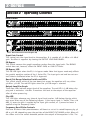
2-Series Graphic Equalizers 131s 215s 231s User Manual Professional Audio Equipment IMPORTANT SAFETY INSTRUCTIONS WARNING FOR YOUR PROTECTION READ THE FOLLOWING: CAUTION RISK OF ELECTRIC SHOCK DO NOT OPEN ATTENTION: R I S Q U E D E C H O C E L E C T R I Q U E - N E P A S O U V R I R W A R N I N G : TO REDUCE THE RISK OF FIRE OR ELECTRIC SHOCK DO NOT EXPOSE THIS EQUIPMENT TO RAIN OR MOISTURE 4HE SYMBOLS SHOWN ABOVE ARE INTERNATIONALLY ACCEPTED SYMBOLS THAT WARN OF POTENTIAL HAZARDS with electrical products. The lightning flash with arrowpoint in an equilateral triangle means that there are dangerous voltages present within the unit. The exclamation point in an equilateral triangle indicates that it is necessary for the user to refer to the owner’s manual. 4HESE SYMBOLS WARN THAT THERE ARE NO USER SERVICEABLE PARTS INSIDE THE UNIT $O NOT OPEN THE unit. Do not attempt to service the unit yourself. Refer all servicing to qualified personnel. Opening the chassis for any reason will void the manufacturer’s warranty. Do not get the unit wet. If liquid is spilled on the unit, shut it off immediately and take it to a dealer for service. Disconnect the unit during storms to prevent damage. NOTICE FOR CUSTOMERS IF YOUR UNIT IS EQUIPPED WITH A POWER CORD. WARNING:THIS APPLIANCE MUST BE EARTHED. The cores in the mains lead are coloured in accordance with the following code: BLUE - Neutral HEED ALL WARNINGS FOLLOW ALL INSTRUCTIONS THE APPARATUS SHALL NOT BE EXPOSED TO DRIPPING OR SPLASHING LIQUID AND NO OBJECT FILLED WITH LIQUID, SUCH AS VASES, SHALL BE PLACED ON THE APPARATUS CLEAN ONLY WITH A DRY CLOTH. DO NOT BLOCK ANY OF THE VENTILATION OPENINGS. INSTALL IN ACCORDANCE WITH THE MANUFACTURER’S INSTRUCTIONS. DO NOT INSTALL NEAR ANY HEAT SOURCES SUCH AS RADIATORS, HEAT REGISTERS, STOVES, OR OTHER APPARATUS (INCLUDING AMPLIFIERS) THAT PRODUCE HEAT. ONLY USE ATTACHMENTS/ACCESSORIES SPECIFIED BY THE MANUFACTURER. UNPLUG THIS APPARATUS DURING LIGHTNING STORMS OR WHEN UNUSED FOR LONG PERIODS OF TIME. Do not defeat the safety purpose of the polarized or grounding-type plug. A polarized plug has two blades with one wider than the other. A grounding type plug has two blades and a third grounding prong. The wide blade or third prong are provided for your safety. If the provided plug does not fit your outlet, consult an electrician for replacement of the obsolete outlet. SAFETY INSTRUCTIONS GREEN andYELLOW - Earth KEEP THESE INSTRUCTIONS BROWN - Live As colours of the cores in the mains lead of this appliance may not correspond with the coloured markings identifying the terminals in your plug, proceed as follows: s4HE CORE WHICH IS COLOURED GREEN AND YELLOW MUST BE connected to the terminal in the plug marked with the LETTER%ORWITHTHEEARTHSYMBOLORCOLOUREDGREENOR green and yellow. s4HE CORE WHICH IS COLOURED BLUE MUST BE CONNECTED TO THETERMINALMARKED.ORCOLOUREDBLACK s4HECOREWHICHISCOLOUREDBROWNMUSTBECONNECTEDTO the terminal marked L or coloured red. This equipment may require the use of a different line cord, ATTACHMENT PLUG OR BOTH DEPENDING ON THE AVAILABLE POWER SOURCE AT INSTALLATION )F THE ATTACHMENT PLUG NEEDS TO BE changed, refer servicing to qualified service personnel who SHOULDREFERTOTHETABLEBELOW4HEGREENYELLOWWIRESHALLBE connected directly to the units chassis. Protect the power cord from being walked on or pinched particularly at plugs, convenience receptacles, and the point where they exit from the apparatus. Use only with the cart stand, tripod bracket, or table specified by the manufacture, or sold with the apparatus. When a cart is used, use caution when moving the cart/apparatus combination to avoid injury from tip-over. CONDUCTOR WIRE COLOR Normal Alt BLACK L LIVE BROWN N NEUTRAL BLUE E EARTH GND GREEN/YEL WHITE GREEN WARNING: If the ground is defeated, certain fault conditions in the unit or in the system to which it is connected can result IN FULL LINE VOLTAGE BETWEEN CHASSIS AND EARTH GROUND 3EVERE injury or death can then result if the chassis and earth ground are touched simultaneously. 2 Refer all servicing to qualified service personnel. Servicing is required when the apparatus has been damaged in any way, such as powersupply cord or plug is damaged, liquid has been spilled or objects have fallen into the apparatus, the apparatus has been exposed to rain or moisture, does not operate normally, or has been dropped. POWER ON/OFF SWITCH: If the equipment has a Power switch, the Power switch used in this piece of equipment DOES NOT break the connection from the mains. MAINS DISCONNECT: The plug shall remain readily operable. For rackmount or installation where plug is not accessible, an all-pole mains switch with a contact separation of at least 3 mm in each pole shall be incorporated into the electrical installation of the rack or building. FOR UNITS EQUIPPED WITH EXTERNALLY ACCESSIBLE FUSE RECEPTACLE: Replace fuse with same type and rating only. MULTIPLE-INPUT VOLTAGE: This equipment may require the use of a different line cord, attachment plug, or both, depending on the available power source at installation. Connect this equipment only to the power source indicated on the equipment rear panel. To reduce the risk of fire or electric shock, refer servicing to qualified service personnel or equivalent. If connected to 240V supply, a suitable CSA/UL certified power cord shall be used for this supply. IMPORTANT SAFETY INSTRUCTIONS LITHIUM BATTERY WARNING CAUTION! 4HISPRODUCTMAYCONTAINALITHIUMBATTERY4HERE ISDANGEROFEXPLOSIONIFTHEBATTERYISINCORRECTLY replaced. Replace only with an Eveready CR 2032 or EQUIVALENT-AKESURETHEBATTERYISINSTALLEDWITHTHE CORRECTPOLARITY$ISCARDUSEDBATTERIESACCORDINGTO manufacturer’s instructions. U.K. MAINS PLUG WARNING $PROGHGPDLQVSOXJWKDWKDVEHHQFXWRIIIURPWKHFRUGLVXQVDIH 'LVFDUGWKHPDLQVSOXJDWDVXLWDEOHGLVSRVDOIDFLOLW\ NEVER UNDER ANY CIRCUMSTANCES SHOULD YOU INSERT A DAMAGED OR CUT MAINS PLUG INTO A 13 AMP POWER SOCKET. 'RQRWXVH WKH PDLQV SOXJ ZLWKRXW WKH IXVH FRYHU LQ SODFH 5HSODFHPHQW IXVH FRYHUVFDQEHREWDLQHGIURP\RXUORFDOUHWDLOHU5HSODFHPHQWIXVHV DUHDPSVDQG0867EH$67$DSSURYHGWR%6 DECLARATION OF CONFORMITY ADVARSEL! ,ITHIUMBATTERI%KSPLOSJONSFARE6EDUTSKIFTINGBENYTTESKUNBATTERISOMANBEFALTAVAPPARATFABRIKANTEN "RUKTBATTERIRETURNERESAPPARATLEVERANDREN ADVARSEL! ,ITHIUMBATTERI%KSPLOSIONSFAREVEDFEJLAGTIGHÍNDTERING5DSKIFTNINGMÍKUNSKEMEDBATTERIAVSAMME FABRIKATOGTYPE,EVÏRDETBRUGTEBATTERITILBAGETIL LEVERANDREN -ANUFACTURERS.AMEDBX0ROFESSIONAL0RODUCTS Manufacturer’s Address: 8760 S. Sandy Parkway Sandy, Utah 84070, USA declares that the product: VAROITUS! 0RODUCTNAME .OTE Paristo voi räjähtää, jos se on virheellisesti asennettu. 6AIHDAPARISTOAINOASTAANLAITEVALMISTAJANSUOSITtelemaan tyyppin. Hävitä käytetty paristo valmistajan ohjeiden mukaisesti. DBX333 0RODUCTNAMEMAYBESUFFIXEDBYTHE%5 Product option: None VARNING! conforms to the following Product Specifications: %XPLOSIONSFARAVIDFELAKTIGTBATTERIBYTE!NVËND SAMMABATTERITYPELLERENEKVIVALENTTYPSOMREKOMMENDERASAVAPPARATTILLVERKAREN+ASSERAANVËNTBATTERIENLIGTFABRIKANTENSINSTRUKTION 3AFETY )%#!MD EMC: %. %. &##0ART Supplementary Information: %,%#42/-!'.%4)# #/-0!4)"),)49 4HISDEVICECOMPLIESWITHPARTOFTHE FCC Rules and the Product Specifications noted on the Declaration of Conformity. /PERATIONISSUBJECTTOTHEFOLLOWINGTWO conditions: sTHISDEVICEMAYNOTCAUSEHARMFUL interference, and sTHISDEVICEMUSTACCEPTANYINTERFERence received, including interference that may cause undesired operation. Operation of this unit within significant ELECTROMAGNETICFIELDSSHOULDBEAVOIDED sUSEONLYSHIELDEDINTERCONNECTING CABLES If you want to dispose this product, do not mix it with general household waste. There is a separate collection system for used electronic products in accordance with legislation that requires proper treatment, recovery and recycling. The product herewith complies with the requirements of the: ,OW6OLTAGE$IRECTIVE%# %-#$IRECTIVE%# 2O(3$IRECTIVE%# 7%%%$IRECTIVE%# 7ITHREGARDTO$IRECTIVE%# AND%#2EGULATIONOF $ECEMBERTHISPRODUCTIS designed, produced, and classified as Professional Audio Equipment and thus is exempt from this Directive. Roger Johnsen 6ICE0RESIDENTOF%NGINEERING 8760 S. Sandy Parkway Sandy, Utah 84070, USA $ATE!UGUST European Contact: 9OURLOCALDBX3ALESAND Service Office or Harman Music Group 8760 South Sandy Parkway Sandy, Utah 84070 USA 0H &AX Private household in the 25 member states of the EU, in Switzerland and Norway may return their used electronic products free of charge to designated collection facilities or to a retailer (if you purchase a similar new one). For Countries not mentioned above, please contact your local authorities for a correct method of disposal. By doing so you will ensure that your disposed product undergoes the necessary treatment, recovery and recycling and thus prevent potential negative effects on the environment and human health. 3 User Manual 2-Series Table of Contents Section 1 - Introduction .........................................................................6 Section 2 - Operating Controls .................................................................7 Section 3 - Connecting the EQ to Your System ...........................................8 Section 4 - Rear Panel Descriptions ..........................................................9 Section 5 - Installation Considerations......................................................9 Section 6 - Operation and Application Notes..............................................10 Specifications........................................................................................11 Service Info If you require technical support, contact dbx Technical Support. Be prepared to accurately describe the problem. Know the serial number of your device - this is printed on a sticker attached to the chassis. If you have not already taken the time to fill out your warranty registration card and send it in, please do so now. You may also register online at www.dbxpro.com. Before you return a product to the factory for service, we recommend you refer to the manual. Make sure you have correctly followed installation steps and operation procedures. For further technical assistance or service, please contact our Technical Support Department at (801) 568-7660 or visit www.dbxpro.com. If you need to return a product to the factory for service, you MUST first contact Technical Support to obtain a Return Authorization Number. No returned products will be accepted at the factory without a Return Authorization Number. Please refer to the Warranty information on the following page, which extends to the first end-user. After expiration of the warranty, a reasonable charge will be made for parts, labor, and packing if you choose to use the factory service facility. In all cases, you are responsible for transportation charges to the factory. dbx will pay return shipping if the unit is still under warranty. Use the original packing material if it is available. Mark the package with the name of the shipper and with these words in red: DELICATE INSTRUMENT, FRAGILE! Insure the package properly. Ship prepaid, not collect. Do not ship parcel post. 4 2-Series User Manual Warranty This warranty is valid only for the original purchaser and only in the United States. 1. The warranty registration card that accompanies this product must be mailed within 30 days after purchase date to validate this warranty. You can also register online at www.dbxpro.com. Proof-of-purchase is considered to be the responsibility of the consumer. A copy of the original purchase receipt must be provided for any warranty service. 2. dbx warrants this product, when bought and used solely within the U.S., to be free from defects in materials and workmanship under normal use and service. 3. dbx liability under this warranty is limited to repairing or, at our discretion, replacing defective materials that show evidence of defect, provided the product is returned to dbx WITH RETURN AUTHORIZATION from the factory, where all parts and labor will be covered up to a period of two years. A Return Authorization number must first be obtained from dbx. The company shall not be liable for any consequential damage as a result of the product’s use in any circuit or assembly. 4. dbx reserves the right to make changes in design or make additions to or improvements upon this product without incurring any obligation to install the same additions or improvements on products previously manufactured. 5. The foregoing is in lieu of all other warranties, expressed or implied, and dbx neither assumes nor authorizes any person to assume on its behalf any obligation or liability in connection with the sale of this product. In no event shall dbx or its dealers be liable for special or consequential damages or from any delay in the performance of this warranty due to causes beyond their control. 5 User Manual 2-Series Section 1 - Introduction Congratulations on your purchase of a dbx 2-Series Graphic Equalizer. The 2-Series represents a major step forward in the performance of entry-level graphic equalizers. From their amazing 10 Hz to 50 kHz frequency response, to its 112 dB dynamic range, the 2-Series offer out of this world specifications with a down to earth price point. Sure to find a home in the studio, on tour and with installed sound venues, the 2-Series is destined to take its rightful place in the lineage of great dbx® signal processors that are the Professional’s Choice™. With such affordable quality, there’s no longer any excuse for compromising your sound. The 2-Series Equalizers include the following features: sS/NEBANDOCTAVE#ONSTANT1FREQUENCYBANDS S4WOBANDOCTAVE#ONSTANT1FREQUENCYBANDS S4WOBANDOCTAVE#ONSTANT1FREQUENCYBANDS s3WITCHABLEBOOSTCUTRANGESOF¢D"OR¢D" sD"PEROCTAVE(ZLOWCUTFILTER s&RONTPANELBYPASSSWITCH s¢D"INPUTGAINRANGE sSEGMENT,%$LADDERSFORMONITORINGOUTPUTLEVELS s8,2AND423)NPUTSAND/UTPUTS s&REQUENCY2ESPONSEOF(ZTOK(Z s$YNAMICRANGEOFGREATERTHAND" Inspection Verify that the equalizer’s package contains the following: s%QUALIZERUNITMATCHINGSERIALNUMBERMARKEDONPACKAGE s!#POWERCORD s/PERATION-ANUAL s2EGISTRATION#ARD s&OURRACKMOUNTSCREWSANDWASHERS If any of these items are missing please contact dbx customer service at the number provided on the back cover of this manual. 6 2-Series User Manual Section 2 - Operating Controls Front Panels 131s- Single Channel 31 Band Graphic EQ 215s- Dual Channel 15 Band Graphic EQ 231s- Dual Channel 31 Band Graphic EQ Input Gain Control This control sets the signal level to the equalizer. It is capable of -12 dB to +12 dB of gain. Its effect is apparent by viewing the OUTPUT LEVEL BAR GRAPH. EQ Bypass This switch removes the graphic equalizer section from the signal path. The BYPASS switch does not, however, affect the INPUT GAIN, or LOW CUT filters. EQ Bypass LED This red LED lights when the EQ is in bypass mode. Note that bypass mode only effects the graphic equalizer section of the 2 Series EQs. The input gain and and low cut controls remain unaffected when the EQ is bypassed. Boost/Cut Range Selection Switch and LEDs 4HISSWITCHSELECTSWHICHOFTHETWOBOOSTCUTRANGESTHEEQUALIZERWILLUSEEITHER ¢D"OR¢D"4HERED,%$LIGHTSWHENTHE¢D"RANGEISSELECTED Output Level Bar Graph These four LEDs indicate output level of the equalizer. The red LED is 3 dB below clipping and is marked as +18 dBu. It monitors the level at the output of the equalizer after all other processing. Clip LED This LED lights whenever any internal signal level reaches 3 dB below clipping which may occur when any of the following happen: 1) the input signal is “hotter” than +18 dBu, 2) excessive gain is applied by the input gain control, or 3) excessive boost is applied using the frequency sliders. Frequency Band Slider Controls %ACHONEOFTHESESLIDERPOTENTIOMETERSWILLBOOSTORCUTATITSNOTEDFREQUENCYBY¢ D"OR¢D"DEPENDINGUPONTHEPOSITIONOFTHE"//34#542!.'%SWITCH7HENALL the sliders are in the center detented position the output of the equalizer is flat. The 7 User Manual 2-Series FREQUENCYBANDCENTERSOFTHESANDSAREMARKEDATRDOFANOCTAVEINTERVALS on ISO standard spacings, while the frequency band centers of the 215s are marked at RDSOFANOCTAVEINTERVALSON)3/STANDARDSPACINGS Low Cut Enable Switch The LOW-CUT switch inserts or removes the 12 dB per octave 50 Hz low-cut filter from the signal path. When the LOW-CUT switch is pushed in, the LOW-CUT filter is IN the audio path. Section 3 - Connecting the EQ to Your System The 2-Series Equalizers have balanced inputs and impedance balanced outputs that can be used with any balanced or unbalanced line-level device. To connect the equalizer to your sound system refer to the following steps: r 5VSOPGGBMMFRVJQNFOUCFGPSFNBLJOHDPOOFDUJPOT r .PVOUFRVBMJ[FSJOBTUBOEBSEXJEUISBDL Install the EQ in a rack with the rack screws provided. It can be mounted above or below anything that does not generate excessive heat. Ambient temperatures should not exceed 113° F (45°C) when equipment is in use. Although the unit’s chassis is shielded against radio frequency and electromagnetic interference, extremely high fields of RF and EMI should be avoided. r .BLFBVEJPDPOOFDUJPOTWJB9-3PS534KBDLTBDDPSEJOHUPBQQMJDBUJPO OFFET Both types of connectors for the inputs and outputs can be used for balanced or unbalanced connections. The use of more than one connector at a time for the inputs could unbalance balanced lines, cause phase cancellation, short a conductor to ground, or cause damage to other equipment connected to the equalizer. More than one output may be used simultaneously as long as the combined parallel load is greater than 2 k7. r 4FMFDUUIFPQFSBUJOHSBOHFXJUIUIF#PPTU$VUSBOHFTFMFDUJPOTXJUDI /05&#FTVSFUPSFEVDFBVEJPMFWFMTBUUIFQPXFSBNQMJGJFSTXIFODIBOHJOH UIFTFUUJOHPGUIJTTXJUDIBTJUNBZHFOFSBUFBOBVEJCMFUSBOTJFOU r "QQMZQPXFSUPUIFFRVBMJ[FS Connect the AC power cord to the AC power receptacle on the back of the equalizer. Route the AC power cord to a convenient power outlet away from audio lines. 8 2-Series User Manual Since the 2-Series Equalizers consume a relatively small amount of power, the units may be left on continuously. Section 4 - Rear Panel Descriptions s 131s- Single Channel 31 Band Graphic EQ s 215s- Dual Channel 15 Band Graphic EQ s 231s- Dual Channel 31 Band Graphic EQ Power Cord Receptacle Connects AC power to the equalizer. Output Connectors 4WOTYPESOFOUTPUTCONNECTORSAREPROVIDEDFOROUTPUTCONNECTIONSMALE8,2TYPE CONNECTORSANDTIPRINGSLEEVEPHONEJACKCONNECTORS Input Connectors 4WOTYPESOFINPUTCONNECTORSAREPROVIDEDFORINPUTCONNECTIONSFEMALELOCKING8,2 TYPECONNECTORSANDTIPRINGSLEEVEPHONEJACKCONNECTORS4HEMAXIMUMINPUT level that the equalizer can accept is typically +22 dBu (ref: 0.775Vrms). Section 5 - Installation Considerations Hookups and Cabling: The 2-Series Equalizers are designed for nominal +4 dBu levels. The equalizers can be used with either balanced or unbalanced sources, and the outputs can be used with either balanced or unbalanced loads, provided the proper cabling is used. 9 User Manual 2-Series A balanced line is defined as two-conductor shielded cable with the two center conductors carrying the same signal but of opposite polarity when referenced to ground. An unbalanced line is generally a single-conductor shielded cable with the center conductor carrying the signal and the shield at ground potential. Input Cable Configurations: The equalizer has an input impedance of 40 k7 balanced and 20 k7 unbalanced. This makes the 2-Series Equalizers’ audio inputs suitable for use with virtually any low source impedance (under 2 k7). Output Cable Configurations: The equalizer’s output is capable of driving down to a 2 k7 load to at least +21 dBu. For maximum hum rejection with a balanced source, avoid common grounding at the equalizer’s inputs and outputs. Most balanced (3-conductor) cables have the shield connected at both ends. This can result in ground loops which cause hum. If hum persists try disconnecting the shield on one or more of the cables in the system, preferably at the input of a device, not at the output. Section 6 - Operation and Application Notes The dbx 2-Series Graphic Equalizers are useful audio signal processing tools in situations where precise frequency control is required across the audible frequency spectrum. When used with an audio spectrum analyzer the EQs can tune any acoustical environment -- from the studio to the concert hall -- to stop ringing, increase clarity, and tailor the overall frequency response of the environment. A real-time spectrum analyzer or other types of audio environment analyzers are very useful in determining the amount of equalization needed. Insert the graphic equalizer between the signal source (usually a mixer) and the power amplifiers (or the crossover if there is one). Adjust the level and equalization as required to yield the desired system response. For optimum signal-to-noise response, the gain structure of the sound system must be properly set up. Each component of the sound system should be set at its nominal operating level, starting with the first element in the system, usually a mixing console. Each element should be run at its nominal operating level in order to take advantage of the maximum signal-to-noise properties of that element. Loudspeaker amplifiers, as the last element in the chain, should be set only as loud as necessary, in order to avoid inducing unnecessary noise into the system. 10 2-Series User Manual Specifications Inputs #ONNECTORS 4YPE Impedance: -AX)NPUT,EVEL #-22 423FEMALE8,2PINHOT % LECTRONICALLYBALANCEDUNBALANCED2&FILTERED Balanced 40 k7, unbalanced 20 k7 D"UBALANCEDORUNBALANCED D"TYPICALLYD"ATK(Z Outputs #ONNECTORS 4YPE Impedance: -AX/UTPUT,EVEL 423MALE8,2PINHOT ) MPEDANCEBALANCEDUNBALANCED2&FILTERED Balanced 1007, unbalanced 507 D"UBALANCEDUNBALANCEDINTOK7 or greater D"MBALANCEDUNBALANCEDINTO7) System Performance "ANDWIDTH &REQUENCY2ESPONSE $YNAMIC2ANGE 3IGNALTO.OISE 4($.OISE )NTERCHANNEL#ROSSTALK (ZTOK(ZD" (ZTOK(ZD" 4YPICALLYD" 4YPICALLYD" D"(ZTOK(Z Function Switches EQ Bypass: ,OW#UT 2ANGE Bypasses the graphic equalizer section in the signal path !CTIVATESTHE(ZD"OCTAVEHIGHPASSFILTER 3 ELECTSEITHERD"ORD"SLIDERBOOSTCUTRANGE Power Supply /PERATING6OLTAGE Power Consumption: Mains Connection: 6!#(Z 15 W IEC receptacle Physical Dimensions S S S 3IZE(X7X$ Product Weight: 6.2 lbs, Shipping Weight 7.9 lbs 3IZE(X7X$ Product Weight: 4.8 lbs, Shipping Weight 6.2 lbs 3IZE(X7X$ Product Weight: 4.8 lbs, Shipping Weight 6.2 lbs Note: Specifications subject to change. 11 3OUTH3ANDY0ARKWAYs3ANDY5TAH 0HONEs&AX )NTL&AX %MAILUSATCUSTOMER DBXPROCOMORVISITUS on the web at: WWWDBXPROCOMsWWWDRIVERACKCOM Printed in China 18-0804V-A