1
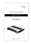
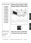
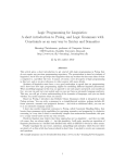
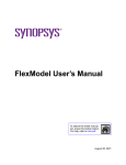
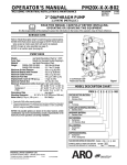
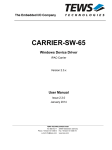
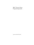
A Verification Environment for PCI-X BFMs in VERA
Renwei Wang, Zongyao Wen
Intellectual Property and System
Synopsys Inc.
[email protected], [email protected]
ABSTRACT
Conventionally, the method for testing Synopsys Bus Functional Models (BFMs) was to typically
create a set of command files, with each of them testing a particular functional area. This process
was and is time consuming because tests for all possible cases must be created manually.
In this paper, we will document a new verification environment that takes the advantage of the
VERA language for verifying Synopsys PCI-X BFMs. The environment produces test bench
code which is highly reusable due to object-oriented programming (OOP) techniques. The effort
on directed testing is greatly reduced by specifying only the areas to be tested. This system can
support three entries: directed testing, random testing, and playback. The play back scheme is
important when a bug is found after days of random run/testing with a single reset. The use of
CoverMeter and a coverage object in VERA is also addressed in this paper. However, a
functional coverage object was not fully implemented.
Using this verification methodology, we are able to improve the quality of our models much
faster. This environment can also be adapted to verify a custom PCI-X design.
Keyword: VERA, PCI-X, Coverage, Random Testing, and Verification
1.0 Introduction
Bus Function Models (BFMs) are widely used to verify synthesizable intellectual property (IP).
They also serve as a second opinion on how to interpret the specification. It is important that
BFMs fully perform the same functionality as the equivalent IPs. In this paper, we will only talk
about the functional verification of PCI-X BFMs. The concept can also be adapted to verify the
function of IPs (refer Section 4.2). The purpose of this paper is to illustrate how we pursued a
trial automatic verification environment by using VERA.
The paper starts with a brief review of the PCI-X protocol and difficulties it has for modelers and
testers. Given that, we will discussion how an environment can be setup to efficiently test and
greatly reduce the coding effort. To create testcases one-by-one is not only time-consuming, but
also impossible for reaching the goal of covering as many function as possible. Experience shows
that verification should be automated. The VERA language fits nicely into this because of its
OOP features and for its ability to generate random stimuli.
The rest of this paper focuses on explaining our approaches for achieving automatic verification.
It is true that developing a good and efficient verification environments needs some degree of
OOP programming in VERA. Following is a brief overview of each section. Section 2.0
introduces the basic PCI-X bus protocol and its complexity for verification. Section 3.0 presents
the system setup. Section 4.0 discusses the details of the verification flow. Section 5.0 goes over
the advanced VERA features valuable to verification, that is, its OOP support and random
stimulus generation. Section 6.0 gives the results achieved by this approach in our own project,
whose goals were achieved. Section 7.0 discusses enhancements to this verification system.
Finally, we conclude the entire paper in Section 8.0.
2.0 PCI-X Bus Protocol
2.1 Basic Concept
PCI-X is an addendum to the PCI Local Bus Specification. PCI is a shared bus to which multiple
requesters and completers are connected. There is only one address-data (AD) bus; therefore,
transactions are divided into address and data phases. A set of control signals is used to indicate
phase transitions and bus ownership.
A transaction is initiated by a requester, which acts as bus master. A completer samples the
control signals and decodes the AD bus during an address phase to determine whether to
respond.
2.2 Variety and Complexity of PCI-X Bus Protocol
The complexity of PCI-X protocol comes from three sources. The first is the type of transactions
a requester can initiate, such as Memory Read, Memory Write, I/O Read, I/O writes, etc. The
second is the type of responses a completer can reply with, such as Retry, Disconnect-on-nextADB, etc. The third is the possible requester and completer configurations, such as 64-bit data,
SNUG San Jose 2002
2
A Verification Environment for PCIX BFMs in VERA
Dual Address Cycles, completer decode speed, TRDY delay, etc. The number of different
transaction variations is the product of all the types minus some illegal combinations.
TransVariations = (NumOfTransTypes * RequesterConfig Types)
*(NumOfRespTypes * CompleterConfigTypes)
– IllegalCombinations
In a real design environment, a requester does not have to support all transaction types, and a
completer does not have to support all response types. However, our models must support all of
them, which makes the verification job more difficult, and thus VERA more valuable to us.
We estimated that there are five hundred thousand variations. There could still be illegal
combinations not excluded, but the scale of the task is certainly on the hundreds of thousands.
3.0 System Setup
The verification system consists of BFMs and VERA verification components. The BFMs serve
both as testing targets and stimulus/response generators. We have two types of PCI-X BFMs,
FlexModels and DesignWare (DW) VERA models. The DW Vera models work like third party
PCIX devices in a system, and they can serve as either a requester or a completer. The project’s
goals were to improve FlexModel quality, so not all verification components for the VERA
models were implemented. Please see Section 7.2 for enhancements required to make the VERA
model fully operational in the test environment.
Figure 1 shows the verification system setup. Gray boxes are BFMs; white boxes are verification
components; dark pattern areas are language boundaries, and light pattern boxes are incomplete
verification components.
SNUG San Jose 2002
3
A Verification Environment for PCIX BFMs in VERA
Figure 1: Verification System Setup
MasterPCIXFlex
ModelCmd
pcixmaster_fx
SlavePCIXFlexM
odelCmd
pcixslave_fx
MasterPCIXFlex
ModelCmd
pcixmonitor_fx
Transaction
PCI-X Bus
Transaction
Dispatcher
Transaction
Generator
DW
Requester
RequesterPCIXD
WModelCmd
DW
Completer
CompleterPCIXD
WModelCmd
DW monitor
Verilog Test Bench
Vera Verificaion Environment
4.0 Verification Flow
4.1 Centralized Representation of PCIX Transaction in Test Bench
An important part of the verification environment is the representation of transaction
information. There can be two approaches. The first approach is to divide the information into
requester related and completer related. The second approach is to create a centralized object that
holds both the requester and completer’s information. Our verification environment used the
latter approach.
The first approach’s advantage is that models can be controlled independently. All of the
completer’s response types can be fed sequentially without knowing whether the response is used
to reply to a single requester transaction or multiple ones. This makes coding easier. The
disadvantage is that the top-level test bench program has little control over which response
matches with which transaction.
SNUG San Jose 2002
4
A Verification Environment for PCIX BFMs in VERA
The second approach’s advantage is that test bench knows exactly what to expect on the bus.
When a transaction uses up all response types as specified, a default response is used. It makes
bus activity more predictable and easier to debug. For example, assume we want to create a
scenario that has one transaction getting a disconnect-on-next-ADB, followed by another
transaction getting a Retry. The disconnect-on-next-ADB would break the first transaction into
two transactions. Using the first approach, the second part of the first transaction would use the
Retry response meant for the second transaction. Using the second approach, the second part of
the first transaction will get a default response, and the Retry response will still occur during the
second transaction. If a failure occurs, we know exactly what is expected on the bus. This
becomes much more valuable when there are hundreds or thousands of transactions in a test
scenario.
The disadvantage of centralizing both the requester and completer’s information is that command
generation becomes difficult. When translating from transaction information to a model
command, all scenarios must be considered. Using the previous example, what if the transaction
is too short and the completer never has a chance to do the disconnect-on-next-ADB? The
Completer ModelCmd class would have to use master information, starting address and byte
count, to calculate the result, and discard responses not being used.
Because we believe the advantage of the centralized representation out-weights its disadvantages,
we chose it for our environment. We would rather spend more time up front rather than having to
go through the pain of figuring out what setup caused a failure in a test. At the end, we also got a
nice surprise when we tried to support partial play back of a failed, long simulation run. Details
of logging and playback are discussed in Section 4.5.
4.2 Layered Verification Environment
The PCI-X verification environment was designed not only for verifying PCI-X, but also
designed to allow the reuse of components in the environment for other BFM’s verification as
well. We divided the verification components into different layers by using VERA’s OOP
features to create a class hierarchy as shown in Figure 2. Each layer’s classes inherit properties
from its super class. The top layer is a set of virtual classes that serve as base for most of the
other classes we needed. The second layer is a protocol independent layer. It is transaction based
at this time. The third layer is a protocol dependent layer, which is PCI-X for this project. The
lowest layer is a module dependent layer, which has FlexModel and DW VERA model support
(the DW VERA model support is an enhancement in Section 7.2). Each layer is enclosed in a
dotted box in Figure 2.
New variations can be added at each layer to expand this environment for other protocol
verification schemes. For example, at the second layer we can add scenario base classes which
can group transactions together into groups; in addition, at the protocol dependent layer we can
add conventional PCI, InfiniBand, or other protocol support. At the module dependent layer we
can add new interfaces to real designs, or other model solutions, given that the design can
provide configuration and/or synchronization schemes during simulation.
SNUG San Jose 2002
5
A Verification Environment for PCIX BFMs in VERA
Figure 2: PCI-X Verification Class Hierarchy
VIPObject
Property
Generator
Dispatcher
ModelCmd
Base Class Layer
Transaction
Transaction
Generator
Transaction
Dispatcher
Protocol Independent Layer
PCIXTransaction
PCIXTransaction
Generator
PCIXRandomTra
nsaction
PCIXRandomTrans
actionGenerator
PCIXTransaction
Dispatcher
PCIXModelCmd
Protocol Dependent Layer
PCIXFlexModelC
md
MasterPCIXFlex
ModelCmd
SlavePCIXFlexM
odelCmd
MonitorPCIXFlex
ModelCmd
PCIXDWModelC
md
RequesterPCIXD
WModelCmd
CompleterPCIXD
WModelCmd
Model Technology Layer
4.3 Multi-termination for a Transaction
As illustrated by the PCI-X specification, a transaction initiated by a requester can be terminated
multiple times by a completer. A requester must resume the burst from where it was terminated.
The following method was mainly set up to check if a requester can resume correctly, and if a
completer can behave as configured. When either one of them does something wrong and should
be caught.
For example, a burst read can be terminated by one of the following termination types:
Disconnect on ADB, Retry, Split, Abort etc. The methodology to create those test cases was to
define an array of termination types of predefined length inside of Transaction. Each element of
the array can have one value out of six options [5]. The array value can be either set by a user in
direct testing, or randomly generated in random testing.
SNUG San Jose 2002
6
A Verification Environment for PCIX BFMs in VERA
With this sequence of termination types, how can we check when the termination type happens,
and if it happens exactly as expected? This job was done at the model’s dependent layer, that is,
FlexModel Slave. The SlavePCIXModelCmd class in Figure 2 provided a non-blocking, but
queued command request. The number of accumulated requests tells the completer how many
times the #DEVSELNN pin had been asserted. The completer decreases the value one at a time
when it answers a transaction. Therefore, if extra requests are issued, then the simulation will
hang, and trigger a time out error. The cause can be from either wrong calculation requests in the
test bench, or the behavior of the IPs themselves. The service routine was created to calculate the
number of requests. First, based on the command encoding of the transaction, it skips the
inapplicable termination types in the array until it meets a proper one. Then, it issues a set of
configurations directives for a completer to perform this termination. The number of requests is
for this type of termination. Meanwhile, the service routine automatically adjusted the new
starting address and byte count where the requester should resume according to the termination
type. The service routine repeats this process until all termination types are walked through, or
the length of transaction is satisfied. Figure 3 illustrates the basic idea here.
Figure 3: Multi-termination Code Example
Example Code How slave does the multi-termination
class SlavePCIXFlexModelCmd extends PCIXFlexModelCmd
{
//
}
task SlavePCIXFlexModelCmd::switchtoMultiTermMode()
{
for ( i = 0; i < valueV; i++)
{
case(multiTermValue[i])
{
VIP_PCIX_DSCNT_ON_NEXT_ADB:
{
// first get the dedicated data from generic property array inside transaction
// check if this command can be disconnected on ADB, otherwise return
// which dscnt , stopB4ADB, datawidth, currentaddr, bytecount to determine new currentadd, bytecunt
updateAddressByteCountbyADB(ADBs, stopB4ADB, dataBusWidth,
currentaddr, currentbytecount, requests);
if(requests == 1) // DSCNT on ADB can happen
{
slaveDev.configure(PCISLAVE_STOP_ASSERT_B4_ADB, stopB4ADB, status);
delay = pcixTransaction.waitStates(……); // get correct latency for slave
slaveDev.request(1, decode, delay);
}
else break; //continue to next possible termination type
}
}// end of case
}// end of for
}
SNUG San Jose 2002
7
A Verification Environment for PCIX BFMs in VERA
4.4 Synchronization between Flexmodels for a Transaction
The transaction dispatcher passes a PCIX transaction to ModelCmd objects, and forks processes
by calling the execute method of each ModelCmd. Each ModelCmd translates the information
inside the transaction into model native commands. For example, requester will do device
configuration and start a read or write; a completer determines preload data properly based on
command type and configures the termination types as in Section 4.3. At the end of the execute
method, a blocking and queued command is forced. This means that all issued commands must
be executed before this command is executed. If extra requests are issued for a slave as discussed
in Section 4.3, then the simulation will hang since forked process are joined all.
4.5 Logging and Play Back Scheme
Each BFM itself provides pin logging and command logging, with which an internal tool can
play back the simulation for each BFM. If the logging for each BFM is turned on and the
simulation runs for hours, dumped log files become extremely large, They are time-consuming
to be reproduced. To reduce the time and achieve an easy play back, only centralized transactions
in test bench are logged during a long simulation. Play back will play those logged transactions.
The error can be easily found by playing back the last couple of transactions. If not, more logged
transactions are used. While playing back transactions, the logging for each BFM is turned on.
Given the small BFM specific log files, the model developer can address the problem in a very
short time through internal tools.
4.6 Flow of the System Verification
Putting things together, we now have the complete picture of a verification flow, as shown in
Figure 4. Transactions can be either generated by the transaction generator or read from a log file
on a disk.
SNUG San Jose 2002
8
A Verification Environment for PCIX BFMs in VERA
Figure 4 Flow of the System Verification
Transaction Generator
Play back
Transaction Dispatcher
ModelCmd
ModelCmd
Blocking Cmd
Message
Checker
timeout
Join all
5.0 Utilization of Advanced VERA Features
In the past, the traditional way of testing our model was to come up with a set of functions to test,
then a list of test cases, and finally implementation test cases by writing model commands.
Because of the complex nature of PCI-X, this method failed to provide us with a complete
verification environment.
5.1 Object Oriented Programming
The first problem we wanted to solve was to avoid writing test cases one-by-one in the model’s
command set. We had to encapsulate transaction information into a data structure, then write a
generator to process and generate model’s commands from the information. VERA’s object
oriented features enabled us to create the data structure, and the generation mechanism
effectively. Example code is in Figure 5.
SNUG San Jose 2002
9
A Verification Environment for PCIX BFMs in VERA
Figure 5:
The Branch up to PCIXTransaction is defined.
Code Example 1 Hierarchy of simplified class definition
--------------------------------------------------------virtual class VIPObject
{
task print(){}
}
virtual class Transaction extends VIPObject // can not be newed
{
protected integer source;
// id of the source of the transaction
protected integer destination;
// id of the destination of the transaction
protected integer numberOfProp=0;
// number of properties in the array
protected Property property[];
// An associative array of properties
protected integer id;
// transaction id
protected bit preloadDataforRead;
// is this read a new one, or read after write
protected integer ReadafterWrite;
// need a read to check previous write? Generator use
// bit flag to generate a read transaction for write if set
task setReadafterWrite( integer inputRAW);
function integer getReadafterWrite();
task setPreloadDataforReadFlag(bit loadFlag);
function bit getPreloadDataforReadFlag();
virtual task initializeRandTrans(randPayloadCls randPayload){} // how can we get random value
virtual task mapAddr(){}
// system address mapping
task new(integer inSource, integer inDestination);
task setPropertyArray(Property inProperty[]); // set the array of properties
}
class PCIXTransaction extends Transaction
{
protected bit multiTermFlag;
// multi-term for a transaction?
task setMultiTermFlag(bit inFlag);
function bit getMultiTermFlag();
task mapAddr()
{
…// map the system address for this transaction
}
// completer latency rule check, returns the valid waits for TRDY pin.
// It is called before issue the request to slave
function integer waitStates(integer inDelay, integer decode, integer addrWidth,
integer abortLimit, integer terminationType, integer cmdType);
task print()
{
… // log the transaction in the meaningful mode to PCIX protocol
}
}
SNUG San Jose 2002
10
A Verification Environment for PCIX BFMs in VERA
5.2 Randomization
There are two types of supported tests: directed (or loop), and random. The directed testing
method recursively generates the combination of given areas. Since direct testing introduced only
few bugs compared with random testing, we focused our efforts only on random testing, which is
discussed next.
5.2.1 Random Stimuli Generation
We have the dispatcher to distribute the centralized transaction to BFMs, with the layers below
the dispatcher being reusable. The remaining problem focused on how we could provide one
transaction after another. The answer was simple. We only needed to randomize the properties
inside of transaction. A class PCIXRandomTransaction was derived from PCIXTransaction, and
inside of it a set of random variables was defined. For each variable, a constraint was
constructed. A continuous range was subdivided into sub-ranges based on the experience of PCIX verification, and each range had a weight variable. The random variable of discrete values had
a similar constraint in that each value has a weight variable. See the example code in Figure 6 for
the constraint for termination of completer. Therefore, if a user is only interested in testing the
Disconnect on Next ADB, in the weight control matrices file, they can be set as shown in the
example code, which also created a directed test case.
So to create a random test case becomes a matter of writing the weight control matrices file. We
can easily pick up the testing area by turning on some weights, and turning off other irrelevant
weights. To test all areas is to assign all weights with positive values. We can also control the
frequency by giving weights different values.
Besides those weight variables, a seed was also recorded for the play back purposes. Other
control parameters were also provided: for example, how many transactions are generated, does
it need to do a proper read after a write, etc.
Each random variable has its own constraint, the legal combination of those random variables is
not guaranteed. There are two ways to make it correct: one is to define a complex constraint
based on the order of random variables; another way is to use post_randomize(). We choose the
latter method because it provides flexibility and easy maintenance.
SNUG San Jose 2002
11
A Verification Environment for PCIX BFMs in VERA
Figure 6: Random Stimuli Generation
class PCIXRandomTransaction extends PCIXTransaction
{
rand
{
// transaction variable declaration
integer slaveTermType;
}
//weight matrix variables and random seed
integer NORMALweight;
integer DSCNTONNEXTADBweight;
integer TARGETABORTweight;
integer RETRYweight;
integer SINGLEDATADSCNTweight;
integer SPLITRESPONSEweight;
constraints slaveTerm{
slaveTermType[0] dist
{
NORMAL:= NORMALweight, DSCNT_ON_NEXT_ADB:=
DSCNTONNEXTADBweight, TARGET_ABORT:= TARGETABORTweight,
RETRY:= RETRYweight, SINGLE_DATA_DSCNT := SINGLEDATADSCNTweight,
SPLIT_RESPONSE := SPLITRESPONSEweight
};
}
task post_randomize() {……} // deal some protocol checking between the generated variable
}
============================================================================
// Random transaction generation
PCIXRandomTransaction RandTrans = new(2,3); // source and destination
RandTrans.setReadAfterWrite(1);
RandTrans. NORMALweight = 0;
RandTrans.DSCNTONNEXTADBweight = 50;
RandTrans.TARGETABORTweight = 0;
RandTrans.RETRYweight = 0;
RandTrans.SINGLEDATADSCNTweight = 0;
RandTrans.SPLITRESPONSEweight = 0;
While(1)
{
RandTrans.randomize();// generate payload
RandTrans.print();
// log the transaction
If( read_transaction){
RandTrans.setPreloadDataforReadFlag(1); // preload data for this read transaction
randTrans.mapAddr();
disatcher.dispatch(randTrans); //blocked and wait until all command is successfully executed by models
}
else
{
RandTrans.setPreloadDataforReadFlag(0); // preload data for this read transaction
randTrans.mapAddr();
disatcher.dispatch(randTrans);
randTrans.commandType= read;
disatcher.dispatch(randTrans);
}
}
SNUG San Jose 2002
12
A Verification Environment for PCIX BFMs in VERA
6.0 Quality Result
In our experience, random testing can not only find bugs faster than directed testing, but it also
produced the bigger yield. Almost 90 percent of the bugs were discovered in the world of random
testing. A lot of burden was put on model developers to quickly fix those bugs generated from
random testing. Based on its productivity, it serves as an important quality measurement for our
three PCI-X Flexmodel BFMs (master, slave and monitor). We started four simulations on four
servers with different seeds, and the result was that the simulation took 202 hours on average of
computer wall clock time, and generated more than one million transactions on average, without
errors. After hitting a product milestone, the random testing runs in the background as both a
gatekeeper of each enhancement, and a “discoverer” of potential bugs.
7.0 Improvements on the System
7.1 Monitor Gap
Like some other verification systems, this system counts on how many areas the monitor covers.
The monitor gap is put in a table and used as a way of improvement.
7.2 Verification between Models from Different Source
Having DW BFMs talk to Flex BFMs has not been fully implemented. The classes at the model
command level are partially done. We can do basic transactions from the Flexmodel to the DW
models, and vice versa. Due to the time constraints of this project, the fully functional
environment (multi terminations) has not been done. To fully verify the communication between
two types of BFMs is out of the scope of this project.
7.3 Coverage
One question frequently asked a verification engineer is the following: "when do you think the
verification is done?" However, the answer is always not as direct as the question.
There is one exit point for a random test: when the coverage goal is reached. How the coverage is
defined is of critical importance. Most often, the line coverage of the source code plays on table.
As we know, even though we have 100 percent line coverage, this does not mean the product is
of good quality. BFMs are no exception to this. The line coverage provided by CoverMeter,
while good, was not complete because errors were still coming in. As discussed in Section 2.2, it
is impossible to have a complete combination of all possible behaviors of PCI-X. As a result, we
proposed a method to define coverage which we called Reduced State Space Coverage (RSSC).
A transaction was defined from a requester’s point of view; with some low-level transactions not
controllable by a requester (for example, completion messages). Thus, we identified a set of
parameters from the point of view of the monitor, since monitor is the “king device” which
knows exactly the activity on the bus.
SNUG San Jose 2002
13
A Verification Environment for PCIX BFMs in VERA
First, we needed an entry point of the feature, and then we searched for all other possible features
in the specification which could produce variations of behavior. Each feature was represented as
a state variable. The combination of those state variables is the complete coverage. For each state
variable, we only picked up representative values or regions as an individual reduced state, so the
coverage becomes the combination of reduced states. With the reduced state space, we can also
define the sequence of combinations. Both the reduced state space and sequences form the
RSSC.
With the current version of the VERA language, it is possible to create such an object. However,
it still needs a certain amount of manual coding for the creation of state bins. It would be better
that VERA had the ability to abstract this type of work and ease the programming burden. The
SynopsysVERA group has been notified of this application enhancement.
The coverage object that is proposed here can be used to provide a quantitative reports on
functional coverage, and thus benefit random testing. We wanted to see whether random testing
generated every corner case. In addition, we did not want to see the random generator producing
the same transactions frequently. It was also desired to provide a closed loop between the
generator and coverage. Therefore, random generator can query the coverage object and
dynamically adjust the weights to cover corner cases very quickly.
8.0 Conclusions and Recommendations
The Object-oriented features provided by VERA can make the testing environment very
manageable with the added benefit of reusable code. Virtual functions and abstract classes hide
the actual implementation of the interfaces. The scheme of random stimuli generation can ease a
lot of work on writing directed testing, providing efficient testing in short period of time. After
the environment was set up, most of time was spent on identifying and fixing issues. The
verification was automated to such a degree that user only needed to specify a certain area to be
tested. Logging can happen at transaction levels during testing. The logs for BFMs are only
turned on at the stage of play back and debugging. Along with those features, we achieved the
goal of making BFMs high quality.
This was the first trial at verifying BFMs in such a way. Many other BFMs may be potentially
tested in this way as well. The regression test suite is still valuable in verifying BFMs standalone.
In order to replace the regression test suite in system verification environment, it is necessary to
implement the coverage to make the system complete.
9.0 Acknowledgements
We would like to thank the support from team players in this project for their contribution in
resolving bugs quickly. The PCI-X Macro cell team from DesignWare at Mt.View deserves
special thanks for their valuable review on our verification methodology. Thanks to IPS
management for allowing us to publish this work.
SNUG San Jose 2002
14
A Verification Environment for PCIX BFMs in VERA
10.0 References
[1]
[2]
[3]
[4]
VERA User Manual Ver.4.5
FlexModel User Manual Latest
PCI-X FlexModel User's Manuals
Application Note for Developing Generic Classes and Methods in VERA Revision 1.0 Oct,
13, 2000
[5] PCI-X Addendum to the PCI Local Bus Specification Revision 1.0, 1999 & 1.0a 2000
SNUG San Jose 2002
15
A Verification Environment for PCIX BFMs in VERA