1
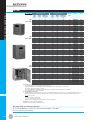
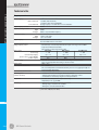
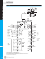
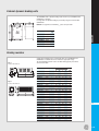
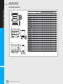
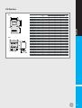
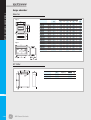
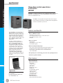
VAT2000
T2000
Micro variable speed drives
Three phase variable speed drives
for AC motors
VAT2000
VAT2000 is a compact, maintenance free, reliable AC drive for three phase
220-240V or 380-460V power source, allowing high accuracy speed
control of standard AC motors.
VAT2000 is an open platform using the latest technology in
both hardware and software, providing advanced application
functions and full motor protection.
Features and Benefits
The VAT2000 is a new generation of
high performance vector AC drives.
Between 10% and 30% smaller than
the former range and using the latest
32 bits microprocessors, the new
range covers the power ratings from
0.4 to 315kW in constant torque, and
up to 370kW in variable torque
applications.
• All in one Multimode drive:
- Sensorless vector control
- Very high performance vector control with sensor
- V/F, advanced torque control
- PM drive
• Easy to operation:
As well as satisfying industry’s
requirement for a top performance
drive, the VAT2000 is hailed as a
truly environmentally friendly drive.
Coupled with a PM motor this drive
can offer up to 20% increase in
energy efficiency at 2.2kW, saving
energy costs. The carefull selection
of materials means that the drives
plastic components are free of
harmful dioxins, and a new soft
sound performance significantly
reduces noise pollution by randomly
altering the carrier frequency during
operation.
- Rotary knob
- Autotuning for vector control
- Removable keypad
• Environmentally friendly design:
- Up to 20% energy saving using a permanent magnet motor
- Dedicated energy saving function for induction motors
- Drives plastic components are free of harmful dioxins
- Soft sound PWM
• Exceptional pack of monitoring, protection and operating functions
• Conform to global standards
Removable keypad
Other features
J
Approvals
CE compliance
UL approval (UL508C) 400V series
up to U2KX45K0S only.
J.8
GE Power Controls
- Extended I/O range
- Advanced functions
- Autotuning
- Torque control
- Soft Sound
- PID control
- Multipump control
- Pattern run
- Programmable speeds
- Traverse function
- Skip frequency
- Speed ratio control
- «S» shape ramp
- Communications
- Built-in RS485 port
- Optional Profibus DP interface
Multi-mode vector drive
Mode 1
Mode 2
V/F control for variable torque loads with advanced torque
control
This mode uses auto-tuning to give voltage vector control in open
loop with the added benefit that, because of a higher continuous
current rating than in constant torque mode, an inverter of one
size lower may be used in order to reduce the purchase cost.
Features include:
1. Special energy saving features for fans and pumps where V/F
ratios are dynamically controlled to optimise the power usage.
2. The drive can auto-tune to two independent motors, so that
one inverter can be used in apllications such as pumping
where a main and standby pump are fed by the same source.
3. Multi-pump control. This is a logogic control system commonly
used where two or more pumps maintain pressure in a
system, one being variable speed abd the others being
brought in as required.
Sensorless vector control
There are many drives which claim to offer sensorless vector
control but we feel that this term is misused and describes a
control system similar to our standard Advanced Torque Control.
We define true Sensorless Vector Control as Flux Vector Control
without encoder. Closed loop vector control requires the use of
an encoder so that shaft position can be used in order to
calculate and control phase angle and shaft speed. Because of
this, all settings within a closed loop environment relate to actual
shaft rotation rather than output frequency.
Developing a method whereby the shaft rotation can be
calculated by very closely monitoring the waveform and feedback
at three output phases of the drive. All of the settings the
VAT2000 in sensorless vector mode are therefore set using
rotational speed and not output frequency.
In addition, incorporate two current loops to control magnetising
current independently. Thus, the VAT2000 can perform almost as
well as a closed loop system and uniquely provide torque at zero
speed.
VAT2000
V/F control for constant torque loads with advanced toruqe
control
This mode uses auto-tuning to give voltage vector control in
open loop.
The main features of this mode are:
1. Build-in PID controller eliminates the requirement, and cost, of
a separate device.
2. Tripless operation. This safe and convenient fetaure is a
combination of:
- the availability of dinamically extend ramp times during
operation if the load is likely to demand a too high current or
regenerate a higher current than the programmed limit.
- automating limiting of the IGBT switching frequency if the
heatsink temperature rises too high.
- the ability to limit current transients caused by shock loads.
- alarms and controlled shutdown in the event of a fault which
is non-life threatening of the drive motor.
3. «Motor Loss Braking»is a system which reduces motor
efficiency during regenerative braking allowing some of the
braking energy to be dissipated from the motor as heat, so
reducing the size (or even eliminating) the brake resistor.
Mode 3
Mode 4
Closed Loop Vector Control
This advanced mode enables motor speed to be varied across a
1000 : 1 speed range, with 0.01% accuracy up to 6 times faster
than conventional drives (30Hz response time).
In addition to outstanding torque performances, this mode
contains a new feature whereby the loss of the encoder signal
will cause the drive to automatically switch into Sensorless
Vector mode. The drive then issues an alarm signal which can be
used as an indicator or as a shutdown signal.
Closed Loop Vector Control requires an Encoder Feedback card.
Mode 5
PM Motor Control
This mode enables the use of ultraefficient PM motors for energy
conservation.
J
J.9
VAT2000
T2000
Micro variable speed drives
VAT2000
Input voltage
Heavy duty / Constant torque (1)
overload 150% 60 sec.
Input
Output
Maximum (3)
power
current
motor power
kVA
A
kW
Light duty / Variable torque (2)
overload 120% 60 sec.
Input
Output
Maximum (3)
power
current
motor power
kVA
A
kW
Protection
degree
Cat. no.
Ref. no.
3ph
200V - 230V
1
1.7
2.7
3.8
5.5
8.3
11.4
15.9
21.1
26.3
31.8
41
50
3
5
8
11
16
24
33
46
61
76
92
118
144
0.4
0.75
1.5
2.2
4
5.5
7.5
11
15
18.5
22
30
37
1.2
2.1
3.0
5.1
7.6
10.0
14.5
19.3
24.2
29.7
37.4
45
55
5
8
11
16
22
33
42
61
76
86
108
134
161
0.75
1.5
2.2
4
5.5
7.5
11
15
18.5
22
30
37
45
IP20
IP20
IP20
IP20
IP20
IP20
IP20
IP20
IP20
IP00
IP00
IP00
IP00
U2KN00K4S
U2KN00K7S
U2KN01K5S
U2KN02K2S
U2KN04K0S
U2KN05K5S
U2KN07K5S
U2KN11K0S
U2KN15K0S
U2KN18K5S
U2KN22K0S
U2KN30K0S
U2KN37K0S
168000
168001
168002
168003
168004
168005
168006
168007
168008
168009
168010
168011
168052
3ph
380V - 460V
1
1.7
2.5
3.8
5.9
9
11.7
15.9
21.4
25.6
30.4
41.5
50
60
75
100
120
150
170
220
300
350
400
1.5
2.5
3.6
5.5
8.6
13
17
23
31
37
44
60
72
87
108
145
173
214
245
321
428
519
590
0.4
0.75
1.5
2.2
4
5.5
7.5
11
15
18.5
22
30
37
45
55
75
90
110
132
160
200
250
315
1.7
2.5
3.8
5.9
9.0
11.7
15.9
21.4
25.6
30.4
41.5
50.5
55
75
100
120
140
170
200
250
330
400
450
2.5
3.6
5.5
8.6
13
17
23
31
37
44
60
73
84
108
147
179
208
242
293
365
479
581
651
0.75
1.5
2.2
4
5.5
7.5
11
15
18.5
22
30
37
45
55
75
90
110
132
160
200
250
315
370
IP20
IP20
IP20
IP20
IP20
IP20
IP20
IP20
IP20
IP20
IP00
IP00
IP00
IP00
IP00
IP00
IP00
IP00
IP00
IP00
IP00
IP00
IP00
U2KX00K4S
U2KX00K7S
U2KX01K5S
U2KX02K2S
U2KX04K0S
U2KX05K5S
U2KX07K5S
U2KX11K0S
U2KX15K0S
U2KX18K5S
U2KX22K0S
U2KX30K0S
U2KX37K0S
U2KX45K0S
U2KX55K0S
U2KX75K0S
U2KX90K0S
U2KX110KS
U2KX132KS
U2KX160KS
U2KX200KS
U2KX250KS
U2KX315KS
168024
168025
168026
168027
168028
168029
168030
168031
168032
168033
168034
168035
168036
168037
168038
168039
168040
168041
168042
168043
168044
168045
168046
3ph
400V
1
1.7
2.5
3.8
5.9
9
11.7
15.9
21.4
25.6
30.4
41.5
50
60
-
1.5
2.5
3.6
5.5
8.6
13
17
23
31
37
44
60
72
87
-
0.4
0.75
1.5
2.2
4
5.5
7.5
11
15
18.5
22
30
37
45
-
1.7
2.5
3.8
5.9
9.0
11.7
15.9
21.4
25.6
30.4
41.5
50.5
55
75
2.5
3.6
5.5
8.6
13
17
23
31
37
44
60
73
84
108
0.75
1.5
2.2
4
5.5
7.5
11
15
18.5
22
30
37
45
55
IP54
IP54
IP54
IP54
IP54
IP54
IP54
IP54
IP54
IP54
IP54
IP54
IP54
IP54
IP54
IP54
U2KX00K4SP54B
U2KX00K7SP54B
U2KX01K5SP54B
U2KX02K2SP54B
U2KX04K0SP54B
U2KX05K5SP54B
U2KX07K5SP54B
U2KX11K0SP54B
U2KX15K0SP54B
U2KX18K5SP54B
U2KX22K0SP54B
U2KX30K0SP54B
U2KX37K0SP54C
U2KX37K0SP54V
U2KX45K0SP54C
U2KX45K0SP54V
169471
169472
169473
169474
169475
169476
169477
169478
169479
169480
169481
169482
169483
169484
169485
169486
(1) Heavy duty / Constant torque ratings
- Ambient temperature -10ºC to 50ºC for all range (IP54 range up to 40ºC)
- Drives up to U2KN22K0S or up to U2KX30K0S allow specified current ratings when carrier frequency is set up to 10KHz.
Above 10KHz, derate output current by 7% per 1KHz.
- Drives above U2KN22K0S or U2KX37K0S and above allow specified current ratings when carrier frequency is set up to 4KHz.
Above 4KHz, derate output current by 7% per 1KHz
J
(2) Light duty / Variable torque ratings
- Ambient temperature -10ºC to 50ºC (IP54 up to 40ºC). Fro drives up to U2KN7K5S derate output current by 2% per 1ºC if ambient temperature exceeds 40ºC
- Maximum recommended carrier frequency is 4KHz. Higher carrier frequency is allowed if drive’s output current is derated according following expression:
VT - CT
Amps, per 1KHz
6
VT = Drive rated current in variable torque
CT = Drive rated current in constant torque
- Ratings are given for standard four poles motors. Otherwise, check motor nameplate
Remark: More information is given in Product Manual
(3) Ratings given are for standard 4 poles induction motors
VAT2000
DC supply
drives for common bus operation
We can supply VAT2000 drives for common bus operation DC supply 270-360VDC or 520-720VDC.
Please ask your dealer for more information.
J.10
GE Power Controls
Optional PCBs Cards
Description
Cat. no.
Ref. no.
12V A/B phase 60kHz; 6V single phase 20kHz,
12VDC 100mA supply output
U2KV23DN1
168087
5V A/B phase differential 250kHz; 5VDC 200mA
5VDC 100mA supply output
U2KV23DN2
168088
5V 6 phase (A, B, Z, U, V, W) 250Hz for permanent
magnet motors
5VDC 100mA supply output
U2KV23DN3
168089
Relay interface
4 additional programmable inputs
2 additional programmable relay outputs
U2KV23RY0
168090
Parallel interface
Frequency setting through parallel 8/12/16 data bits
U2KV23PI0
168091
Serial communication interface
Additional RS232C/485 serial port
U2KV23SL0
168092
Profibus DP communication interface
Standard field bus interface
U2KV23SL6
168093
3m
1m
U2KV23W103
U2KV23W101
U2KV23W123
U2KV23W113
168102
168103
168104
168105
3
VAT2000
Encoder interface
Accessories
Extension cable for keypad
Extension cable for keypad
Drive to terminals RS485 cable
Drive to 15 pin D-sub connector
RS485 cable
Drive to PC RS232 cable
Includes RS232/485 converter
J
U2KV23CNVKIT 168106
J.11
VAT2000
T2000
Micro variable speed drives
Technical data
Frequency control
Control method
Carrier frequency
All digital control sine wave approximation PWM
Mono-sound mode
Soft sound mode
Output frequency resolution
Frequency setting resolution
Digital
Analogue
Frequency accuracy
Digital
Analogue
Output frequency
1 to15kHz (1kHz increments)
1 to 8kHz for drives above U2KX45K0S
Average frequency 2.1 to 5kHz with 3 or 4 tone modulation
0.01Hz
0.01Hz
0.025%, respect maximum frequency
± 0.01% at 25 ±10ºC
± 0.1% at 25 ±10ºC
From 0 to 440Hz in V/f control mode
From 0 to 120Hz in Vector control mode
Control specifications
Voltage frequency control
Vector control
Control range
Constant output range(*)
Speed accuracy (at Fmax.⊕50Hz)
Control response
Automatic tuning
Starting torque
Acceleration/deceleration time
Acceleration/deceleration mode
Operating system
(3 modes selectives)
Stop system
DC braking
Constant torque, constant output and reduction torque set in range from 3 to 440Hz
Torque Boost: Manual and automatic
Max. torque boost: allows improved V/f control
Sensorless
With sensor
For PM motors
1 : 100
1 : 1000
1 : 100
Up to 1 : 2
Up to 1 : 4
Up to 1 : 1.2
± 0.5%
± 0.01%
± 0.01%
5Hz
30Hz
Automatic measurement of motor constants and setting of critical parameters.
There are two independent Auto-tuning for all control modes.
200% or more
0.01 to 60000 sec.
Two sets of independent acceleration/deceleration, plus one set for jogging and eight sets
more for program ramp function
Linear and S type ramp selection
- Forward run or reverse run using two external dry contacts
- Run/Stop and forward/reverse changeover using two external dry contacts
- Forward/Reverse run and stop using three external push-buttons
Selectable either Ramp down to stop or coast to stop,
idependently for run, jog and EMS
- Braking stop frequency, set between 0.1 and 60.0Hz
- Braking voltage, set between 0.1 and 20.0%
- Braking time, set between 0.0 and 20.0 s.
(*) from 150 to 7200 rpm (max. 120Hz)
J
J.12
GE Power Controls
Technical data (continued)
Operation functions
Multi speed
Ratio interlock
VAT2000
Frequency jump
Slip compensation
Auto-run function
Others
8 fixed speed selectable with independent acceleration/deceleration ramps
for each speed
Output frequency or speed is operating according:
Y = Ax + B + C
x : frequency or speed setting
A : (gain) 0.000 to ±10.000
B : 0.00 to ± 440Hz (0 to ±7200min-1 with max.:120Hz in Vector control mode)
C : auxiliary input (AUX)
Upper and lower limits available
Up to three areas / Width can be varied between 0.0 and 10Hz
Slip compensation gain for V/f operation only from 0.0 to 20.0%
10-step automatic run function / Synchronous / Asynchronous selective
PID, Pick-up, Auto-start, Traverse, Multipump control, reverse run protection and Restart
after instantaneous power failure
External I/O
Operation keypad
Detachable IP54 unit with 5 digit LED display and eight status LED signals.
Includes three set keys and fast tuning knob system.
Door mountable by 3m extension cable
Input sequence
Output sequence
Three fixed inputs and five programmable to more than 30 functions
One fixed dry contact (fault), one dry contact and three open collector outputs all
programmable to more than 20 functions, like speed detection precharging, reverse run,
speed reached, direction, current reached, speed, acceleration, fault code, etc
FSV: 0 to 10V / 0 to 5V / 1 to 5V
FSI: 4 to 20mA / 0 to 20mA
AUX: 0 to ±10V / 0 to ±5V / 1 to 5V
Source potentiometer: 10V DC (2k2Ohms)
Two 0-10V programmable with output frequency, voltage, current, DC voltage, etc
Frequency settings
Meter outputs
Protection features
Prevention
Trip
Fault history
Overload level
Retry
Overcurrent and Overvoltage limit, Overload warning signal
Overcurrent, overvoltage, undervoltage, IGBT fault, overload, temperature rise, ground
fault, other self-diagnosis
The last four faults are recorded including in each:
main cause, secondary cause, output current and output frequency at the fault time
CT: 150% for 1 minute, 170% for 2,5 seconds
VT: 120% for 1 minute, 125% for 1second
For frequencies below 1Hz, overload of 75% during 60 seconds
Automatic reset after a fault. Adjusable from 0-10 tries
Operating environment
Installation
Working temperature
Relative humidity
Altitude
Vibrations
Indoor, with atmosphere free from corrosive or explosive gases, dust, steam or oil mist
-10 to +50ºC
max. 95% RH, non condensing
1000 m. max.
4.9 m/s2
J
J.13
VAT2000
T2000
Micro variable speed drives
I/O wiring
DBR driving unit (option) (3)
MCCB
MOTOR
POWER
SUPPLY
ANALOGUE INPUT
Frequency
setting
(voltage)
2k2Ω, 2W
Frequency
setting
(current)
Aux. setting
DC ± 10V
DC 0-10V
ANALOGUE OUTPUT
Voltage
output
(0-10V)
load max.
1mA
(5)
(5)
(5)
DIGITAL OUTPUT
DIGITAL INPUT
Max. 1A 250V AC
or 30V DC
Max. 0,4A 250V AC
or 1A 30V DC
Free voltage
input
(5mA per
signal)
Standard setting
Open collector
Max. 30VDC 50mA
J
RY0V (4)
(1)
(2)
(3)
(4)
(5)
J.14
Remove the link between L1 - L2 it using optional DC reactor
Dynamic braking included for drives up to U2KN7K5S and U2KX7K5S
Dynamic braking for drives U2KN11KS, U2KX11KS and larger is performed with external dynamic braking units
No connection shell be made between RY0V and COM since this section is insulated
Three COM terminals are internally connected
GE Power Controls
To comply with
UL, use at
30VAC/DC
or lower
Notes
VAT2000
J
J.15
VAT2000
T2000
Micro variable speed drives
I/O terminal board specifications
Terminals
Function
Description
Control terminal board
Digital inputs
RY0, RY24
PSI1 ~ PSI5
EMS
RESET
Analogue inputs
RUN
FSV
FSI
AUX
Analogue outputs
COM
FM
AM
COM
P10
Digital outputs
RC, RA
FC, FA, FB
PS01
PS02
PS03
PS0E
Relay input common
Programmable inputs
Emergency stop
This is a common terminal for relay input signals specified below
These inputs can be arbitrarily set to any of input sequence functions
If EMS is ON while the VAT2000 is stopped, all operational commands are cancelles. If it is ON during operation,
the VAT2000 is led into stopping sequence (ramp down stop or coast-to-stop are available.
It is also possible to output this signal as a fault (FLT).
Fault reset
A faulty condotion is reset. With this signal, a fault status output (FLT LED, FAULT relay operation) is turned OFF
and operation becomes possible
Forward run
This is a command for forward run. Run/Reverse mode by permanent or pulse command can be selected
Voltage/Frequency
This is mainly used for setting frequency (speed). The maximum speed setting is available at 10V input.
This input is valid when VFS function is ON
Current/Frequency
This is mainly used for setting frequency (speed). The maximum speed setting is available at 20mA input.
This input is valid when IFS function is ON
Auxiliary input
This is mainly used for setting frequency (speed). The maximum speed setting is available at ±10V input.
This setting is valid when AUX function is ON
Analogue input common This is a common terminal for FSV, FSI and AUX signals
Frequency meter
This is a voltage output signal for a frequency meter. In a standard mode, a 10V output is available at the
maximum frequency. This output voltage can be adjusted to 0.2 to 2.0 times 10V (max. output is, however,
approximately 11V). Internal parameters other than those of frequency can also be output (C13-0, C14-0)
Ammeter
This is a voltage output signal for ammeter. In a standard arrangements, an output of 5V is available for the
rated current. This output voltage adjustment of 0.2 to 2.0 times of 5V is also available. Internal parameters
other than those of current can also be output
Analogue output common This is a common terminal for a frequency meter and ammeter
FSV source
This is a 10V source used when a potentiomenter is connected to the FSV input circuit
The potentiometer should be of 2W and 2k2Ω
RUN
FAULT
READY
Current detection
Frequency speed
Open collector
output common
Dry relay contact assigned to RUN function as default. Programmable to other functions as well
Dry relay contact assigned to FAULT function. It operates when a fault occur
Programmable open collector output assigned to READY function as default
Programmable open collector output assigned to current detection function as default
Programmable open collector output assigned to speed detection as default attainment
This is a common terminals for the PS01, 2 and 3 outputs
All digital outputs can be set to any of output sequence functions
Input sequence functions
R RUN
Reverse run
F JOG, R JOG Forward/Reverse jogging
J
J.16
HOLD
BRAKE
C SEL
Hold
DC brake
Ramp selection
I PASS
VFS
IFS
AUX
PROG
CFS
S0 to S3, SE
Ratio interlock bypass
Speed setting 1
Speed setting 2
Speed setting 3
Program functions
CPU setting
Program setting
FUP
FDW
BUP
BDW
IVLM
AUXDV
PICK
EXC
ACR
PCTL
COP
LIM 1
LIM 2
CPASS
MCH
RF0
TRQB1
TRQB2
DROOP
DEDB
Frequency up
Frequency down
Bias up
Bias down
Bias ratio control
Dual settings
Pick-up
Pre-excitation
ACR
P control
CPU operation
Drive torque limiter
Regenerative torque lim.
Ramp bypass
MAchine time constant
0 setting
Torque bias 1
Torque bias 2
Drooping changeover
Dead band setting
GE Power Controls
This is a command for reverse run
These are jogging commands. If this signal is ON while RUN is OFF, operation then conforms to the setting of
jogging (A00-1 or 3). For stopping, either ramp down stop or coast-stop is available
This is a stop signal used when Forward/Reverse command is operated by push-buttons
DC brake can be operated with this signal
Accel./decel. ramp performance is switched over. ACCel./Decel. time 2 (B10-0, 1) is available with ON,
and Accel./Decel. time 1 (A01-0, 1) is available with OFF
Ratio interlock operation is bypassed
Enables frequency (speed) setting from analog input FVS (C07-0)
Enables frequency (speed) setting from analog input IFS (C07-1)
Enables frequency (speed) setting from analog input AUX (C07-2)
Used for multiple speed setting. Selection of up to 8 fixed speed (PROG0 ~ PROG7) is made with S0 ~ S3, SE
Enables frequency (speed) setting for a serial port
When PROG is ON, the program frequency (8 fixed speeds) (B11-0 up to 7) is enabled.
BCD or direct speed selection are allowed (B11-8)
Raises the output frequency or motor speed (A00-0, A00-2)
Decreases the output frequency or motor speed
Raises the output frequency set through PROG function
Decreases the output frequency set through PROG function
Enables BUP or BDW functions
Enables secondary settings (dual motor operation)
While this signal is ON, pick-up operation is effected as soon as RUN or R RUN is ON
Allows pre-excitation, establishing flux in the motor without generating torque
Enables ACR operation
ASR control is changed from the PI control to the P control
Enables command control from the serial port
The drive torque is limited by the analog input or serial transmission when enabled
The regenerative torque is limited by the analog input or serial transmission when enabled
The ramp function is bypassed when CPASS is enabled
Enables machine time constant compensation in ASR block
The speed setting is changed to 0 rpm.
The torque bias input 1 is enabled
The torque bias input 2 is enabled
Enables Drooping function (B13-5)
The dead band setting of ASR is enabled (B14-0)
I/O terminal board specifications (continued)
Terminals
Function
Description
Output sequence functions
Run
Fault
Charge completed
Ready (1)
Ready (2)
Local
Reverse run
Current detection
Speed attainment
Speed detection (1)
Speed detection (2)
CPU control
Fault code 0 to F
Acceleration
Deceleration
Dual selection
Minor fault
Fan control
ASW
ZSP
Auto-start wait
Zero speed
This turns ON during running, jogging or DC braking (C00-7)
This turns ON during a fault
This turns ON when the DC main circuit voltage reaches right voltage level at power ON
This turns ON when there is no fault, EMS is not activated, and pre-charging is completed
This turns ON when there is no fault, EMS is activated and pre-charging is completed
This turns ON when the operation mode is local (operation from the operation panel)
This turns ON while the motor is reverse running
This turns ON when the output current reaches the detection level (C15-1) or higher
This turns ON when the output frequency (speed) reaches the set frequency (speed) (C15-0)
This turns ON when the output frequency (speed) reaches the speed set level (C15-2)
This turns ON when the output frequency (speed) reaches the speed set level (C15-3)
This turns ON when serial transmission operation is selected
After a fault this outputs the fault code with a 4-bit binary format
This turns ON during acceleration
This turns ON during deceleration
This turns ON when the secondary drive parameter setting is validated
This turns ON during a minor fault
This turns ON during running, jogging, pre-excitation and DC braking. A three minute off delay is provided,
so even if the above operations turn OFF, this control will not turn OFF for three minutes.
This is used for external fan control
This is ON while Auto-start delay time (C08-0)
Tis turns ON when the output frequency (speed) is below the level set with (C15-4)
VAT2000
RUN
FLT
MC
RDY1
RDY2
LCL
REV
IDET
ATN
SPD1
SPD2
COP
EC0~EC3
ACC
DCC
AUXDV
ALM
FAN
Remark: ON means contact is closed
J
J.17
Micro variable speed drives
VAT2000
T2000
Auto-tuning
Soft Sound
The VAT2000 is performed with an Auto-tuning function which simplifies the adjustment of critical control parameters. The Automatic
tuning can be performed in four mode of operation, V/f Constant
Torque, V/f Variable Torque, Vector Sensorless, Full Vector with
sensor.
VAT2000 Soft Sound technology reduces the characteristic whine
from inverter-driven motors and eliminates the side-effects of conventional noise reduction methods, specifically that of raising the
carrier frequency.
Soft Sound varies the carrier frequency in one of two fixed patterns,
from a user-selected base frequency (between 2.1kHz and 5kHz). By
keeping the carrier frequency range low, torque performance is
notably better tha a high-frequency carrier.
The high frequency induced problems of hot running, degrading of
winding insularion, arcing across motor bearings, high leakage
currents, interference,.... These are decreased by using Soft Sound
carrier frequency.
Auto-tuning procedure
Input inverter and motor ratings
Select the drive mode
Soft Sound
Run the drive
(run the tuning)
Auto-tuning error
Auto
tuning
OK
Error
displayed
V/f or Vector related parameters are
automatically set
Auto-tuning is complete
Drive and motor ratings
B00/1-0
B00/1-1
B00/1-2
B00/1-4
B00/1-5
B00/1-6
B00/1-7
B01-8
Input voltage (V)
Motor rated output voltage (kW)
Number of motor poles (Pole)
Max. speed (min-1)
Base speed (min-1)
Motor rated current (A)
Carrier frequency
Number of encoder pulses (P/R)
Drive mode
C30-0 = 1
C30-0 = 2
C30-0 = 3
C30-0 = 4
C30-0 = 5
V/f Constant torque
V/f Variable torque
Vector sensorless
Full vector
PM motor control
J
J.18
GE Power Controls
Mono Sound
Vector control system.
Speed block diagram
The VAT2000 performs an high-end Vector control system, which
allows speed accuracy up to 0.01% using encoder feedback, and up
to 0.5% in sensorless. The dynamic response is excellent in all
cases.
The speed control block diagram is given below
P control
gain
Speed
setting
Torque
limiter
Torque
current
Current
detection
Torque
command
Disturbance
observer
Speed
detection
VAT2000
I control
gain
Detected motor
speed
Control
Corriente
Excitación
Estimated motor speed
Sensorless
vector control
Motor
speed
Flux observer
&
Speed
estimation
Vector control
with sensor
V/f Control. ATC system
The VAT2000 includes an ATC (Advanced Torque Control) function,
which improves the starting torque in the traditional V/F control
systems allowing up to 200% torque with standard induction motors.
The Automatic tuning function set automatically drive parameters,
avoiding difficult manual adjustments.
The ATC block diagram is given below
Slip compensation
setting
(A02-5)
Automatic torque boost
selection
(A02-1)
Overload limit
function
Set frequency
Manual torque boost
setting
(A02-2)
Manual torque boost
selection
(A02-0)
Voltage
command
J
Square reduction torque
setting
(A02-3)
R1 drop compensation
setting
(A02-4)
Frequency
command
Automatic torque boost
selection
(A02-1)
Maximum torque boost
setting
(A02-6)
J.19
VAT2000
T2000
Micro variable speed drives
Ratio interlock function
This function allows full control ratio of speed setting and motor speed.
Useful to synchronize several motors at different speed ratio. Ratio
interlock setting function includes up/down limits, up/down speed
setting increments and co-ordination between two analogue inputs.
(C07-3)
Bias
FSV, FSI, PC
serial interface
option
Upper/lower limit
Frequency
(speed)
command
Input
Bias
increase/
decrease
buffer
Coefficient
(B06-0)
Bias
(B06-1, 4)
PID Control
This function allows control of external conditions by using a feedback signal. Useful for slow process control like water pressure or
flow, temperature by fans, etc
Pressure
sensor
FSV or FSI
Pump
C12-4 (gain)
AUX / FSI
Aux: 0-10V, FSI:4-20mA
Converter
Multi-pump control
One pump is variable speed controlled and up to five more controlled
ON/OFF by the digital outputs provided in the VAT2000. The water
pressure in the pipe system is controlled to be constant according the
setting input in the VAT2000’s PID. The pumps are automatically
shifted in order to ensure same average working time. As standard
the drive provide control up to 3 ON/OFF controlled pumps. By using
optional card U2KV23RY0, then operation is allowed up to 5 pumps.
Example of system configuration (when operating five ON/OFF control pumps)
Pressure
setting
Speed controlled
pump
ON / OFF pump 1
J
ON / OFF pump 2
ON / OFF pump 3
ON / OFF pump 5
Converter
J.20
GE Power Controls
Pressure transducer
ON / OFF pump 4
Pressure transducer
4-20mA
Main
pump
Pump 1
Pump 2
Pump 3
Control ON/OFF auxiliary pumps
VAT2000
Speed controlled pump
Operation and pump shift sequence
PID
output
PS01
pump 1
PS02
pump 2
(1)
(2)
(3)
(4)
Pump with shortest time operation
Pump with longest time operation
Pump with longest time operation
Changeover ignored as time is less
than adjusted in timer T1
(5) Pump with longest time operation is
OFF if running time is over T2.
A pump with shortest time operation
in ON
(6) VAT2000 is stopped. Restart is
automatically produced if PID leaves
LLT level
PS03
pump 3
PS04
pump 4
PS05
pump 5
Stand-by status
T1 = Hold time
T2 = Continuous operation time limit
T3 = Changeover time
PID
output
Time
PS01
pump 1
J
PS02
pump 2
PS03
pump 3
Operation
Restart
VAT2000
J.21
VAT2000
T2000
Up to ten steps automatic operation.
Useful for machines working in a repeated cycle.
Frequency (speed)
Micro variable speed drives
Pattern run
Time
Step-0
Step-1
Step-2
Step-3
Step-4
RUN
Traverse
Usefull function for winding textil equipment.
The traverse centre frequency, can be selected from either analog
input setting, keypad setting or programmable fixed speeds.
Retry
Output frequency
Allows automatic restart after a fault. Provides up to 10
programmable re-tries with programmable time between tries.
J
Motor speed
Time
Internal
FLT
1
J.22
GE Power Controls
Waiting time after trip by Overcurrent,
2
3
4
Pick-up achieved and retry finished
Pick-up and retry
High efficiency operation
(Energy saving)
During V/f constant operation, the non-load loss is large with motor
unloaded or with a small load, and the motor efficiency drops
remarcably. Thus, this function automatically decreases output voltage according to the load, improving motor efficiency.
Sliping may increase during high-efficiency operation so is recommended to use the automatic slip compensation. Autotuning will help
for right adjustment.
Output voltage
V/F setting voltage
V/f setting
voltage
100%
Output voltage fluctuation
at frequency f
100%
C25-1 setting (10-100%)
Lower limit of output voltage
to be reduced
C25-1
(10~100)
Time
Reduced
voltage
C25-0
(0.1~30.0)
VAT2000
Output voltage
Frequency
f
Frequency jumps
By this function, the motor’s mechanical resonance at a specific
frequency can be skipped.
Communications
Built-in with RS485 port and ASCII communication protocol.
Optional Profibus DP interface.
Other communication interfaces in development.
Fault history
The last four faults are coded and saved in a internal buffer.
J
J.23
VAT2000
T2000
Micro variable speed drives
Dimensional drawings
Dimensional drawings and weights
Cat. no.
Supply
Supply
200-230V 380-460V
N00K4
N00K7
N01K5
N02K2
N04K0
X00K4
X00K7
X01K5
X02K2
X04K0
Cat. no.
Supply
Supply
200-230V 380-460V
X05K5
X07K5
N05K5
N07K5
X11K0
X15K0
X18K5
N11K0
N15K0
Cat. no.
Supply
Supply
200-230V 380-460V
X22K0
N18K5
X30K0
N22K0
N30K0
X37K0
N37K0
X45K0
X55K0
X75K0
X90K0
X110K
X132K
X160K
X200K
X250K
X315K
J
J.24
GE Power Controls
A
170
170
170
170
170
A
Dimensions (mm)
B
C
D
E
243
243
243
243
243
162
162
162
162
162
155
155
155
155
155
228
228
228
228
228
Dimensions (mm)
B
C
D
E
216
216
216
216
265
265
265
265
265
275
275
275
275
360
360
360
360
360
A
Dimensions (mm)
B
C
D
E
310
310
310
342
342
342
342
420
420
480
480
488
488
680
870
870
500
500
500
590
590
590
590
690
690
740
740
980
980
1100
1300
1300
169
169
169
169
228
228
228
228
228
253
253
253
307
307
307
307
309
309
352
352
358
358
379
379
379
201
201
201
201
245
245
245
245
245
200
200
200
200
200
200
200
300
300
400
400
320
320
500
600
600
260
260
260
260
340
340
340
340
340
480
480
480
570
570
570
570
686
686
714
714
956
956
1070
1270
1270
Ød
Main
circuit
terminal
Weight
(kg)
6
6
6
6
6
M4
M4
M4
M4
M4
3.5
3.5
3.5
3.5
3.5
Ød
Main
circuit
terminal
Weight
(kg)
7
7
7
7
7
7
7
7
7
M4
M4
M5
M5
M5
M5
M5
M6
M6
6
6
6
6
13
13
13
13
13
Main
circuit
terminal
M6
M8
M8
M8
M8
M8
M8
M10
M10
M10
M10
M10
M10
M16
M16
M16
Weight
(kg)
Ød
10
10
10
10
10
10
10
10
10
10
10
13
13
15
15
15
26
26
26
55
50
60
50
55
60
65
70
90
100
210
300
300
Dimensional drawings series IP54
Dimensions (mm)
Series IP20
Cat. no.
+
FeRIA WM
cabinet
U2KX00K4SP54B
U2KX00K7SP54B
U2KX01K5SP54B
U2KX02K2SP54B
U2KX04K0SP54B
U2KX00K4S
U2KX00K7S
U2KX01K5S
U2KX02K2S
U2KX04K0S
+
600 x 400 x 250
Ref. no.: 813015
U2KX05K5SP54B
U2KX07K5SP54B
U2KX05K5S
U2KX07K5S
+
600 x 600 x 300
Ref. no.: 813018
U2KX11K0SP54B
U2KX15K0SP54B
U2KX18K5SP54B
U2KX11K0S
U2KX15K0S
U2KX18K5S
+
800 x 600 x 400
Ref. no.: 813182
U2KX22K0SP54B
U2KX30K0SP54B
U2KX22K0S
U2KX30K0S
+
800 x 600 x 400
Ref. no.: 813182
U2KX37K0SP54C
U2KX37K0SP54V
U2KX45K0SP54C
U2KX45K0SP54V
USKX37K0S
U2KX37K0S
U2KX45K0S
U2KX45K0S
+
1200 x 800 x 400
Ref. no.: 813185
B
D
K
J
600
600
800
1200
400
600
600
800
250
300
400
400
290
490
490
690
326
526
526
726
VAT2000
Series IP54
Cat. no.
H
IP54 enclosure includes in addition to drive, an EMC filter, enclosure’s cooling
fan and I/O terminals
J
J.25
VAT2000
T2000
Constant torque ratings
Power
supply
VAT2000
Stand-alone option
DBR
unit
MCCB or
fuse
MC
Noise
filter
Main circuit
wiring device
Absorber
Micro variable speed drives
External accessories
Built-in PCB option
Stand-alone options
Noise filter
U2KF-
PR-
This device supresses the
elctromagnetic noise generated by
the inverter. It may be required for
EMC compliance (CE)
DBR unit
U2KV23DBU-
This module provides dynamic
braking capacity to drives larger
than 7.5kW (U2KN07K5S or
U2KX07K5S).
Always install appropriate braking
resistor
ACL
ACR-
If the line impedance is too low the
current ripple trough input rectifier
become excessive and may result
in inverter damage. This may
happen when the power supply
transformer exceeds 10 times the
inverter unit capacity, so always
install reactors in this case.
Reactors are also effective improving the power factor and suppressing the current high harmonics. The
power factor will be approx. 0.9.
J
DCL
DCR-
Same benefits than ACL reactors,
note however that ACL provides
additional protection to input rectifier
Surge absorber
ACFR-
&
N11P34018
This device protects the motor
against surge voltage. It is applicable to 400-460V systems, and may
be required if output wiring to motor
exceeds of 40m length.
The surge absorver is composed
by one output reactor and a RC
filter
Cat. No
Losses
W
U2KN00K4S
U2KN00K7S
U2KN01K5S
U2KN02K2S
U2KN04K0S
U2KN05K5S
U2KN07K5S
U2KN11K0S
U2KN15K0S
U2KN18K5S
U2KN22K0S
U2KN30K0S
U2KN37K0S
U2KX00K4S
U2KX00K7S
U2KX01K5S
U2KX02K2S
U2KX04K0S
U2KX05K5S
U2KX07K5S
U2KX11K0S
U2KX15K0S
U2KX18K5S
U2KX22K0S
U2KX30K0S
U2KX37K0S
U2KX45K0S
U2KX55K0S
U2KX75K0S
U2KX90K0S
U2KX110KS
U2KX132KS
U2KX160KS
U2KX200KS
U2KX250KS
U2KX315KS
49
62
84
117
153
215
301
420
506
708
757
1192
1491
63
83
111
129
175
275
345
369
481
550
675
876
945
1175
1558
2020
2509
3343
3906
4915
6520
7848
9026
Fuses
MCCB
Series
(1) (A)
(2) (A)
MC
20
20
50
60
110
125
225
225
250
400
500
500
600
10
10
20
30
50
60
90
110
125
175
225
250
300
400
400
500
700
800
800
1200
1600
200
2000
5
5
10
15
20
30
40
75
75
100
150
150
200
5
5
5
5
15
20
30
40
40
50
50
75
100
100
150
200
300
300
350
400
500
700
800
CL00
CL00
CL00
CL00
CL01
CL02
CL04
CL04
CL06
CL07
CL09
CL10
CK75
CL00
CL00
CL00
CL00
CL00
CL00
CL02
CL04
CL04
CL04
CL06
CL06
CL07
CL09
CK75
CK08
CK85
CK09
CK09
CK95
CK10
CK11
CK12
Variable torque ratings
VAT2000
Cat. No.
U2KN00K4S
U2KN00K7S
U2KN01K5S
U2KN02K2S
U2KN04K0S
U2KN05K5S
U2KN07K5S
U2KN11K0S
U2KN15K0S
U2KN18K5S
U2KN22K0S
U2KN30K0S
U2KN37K0S
U2KX00K4S
U2KX00K7S
U2KX01K5S
U2KX02K2S
U2KX04K0S
U2KX05K5S
U2KX07K5S
U2KX11K0S
U2KX15K0S
U2KX18K5S
U2KX22K0S
U2KX30K0S
U2KX37K0S
U2KX45K0S
U2KX55K0S
U2KX75K0S
U2KX90K0S
U2KX110KS
U2KX132KS
U2KX160KS
U2KX200KS
U2KX250KS
U2KX315KS
Losses
W
Fuses
(1) (A)
MCCB
(2) (A)
Series
MC
62
84
117
153
215
301
420
506
708
757
1032
1341
1657
83
111
129
175
275
345
369
481
550
675
876
1080
1104
1437
2091
2473
2998
3758
4637
5566
7266
8745
10061
20
50
60
110
125
225
225
250
400
500
500
600
600
10
20
30
50
60
90
110
125
175
225
250
300
400
400
500
700
800
800
1200
1600
2000
2000
2600
5
10
15
20
30
40
75
75
100
150
150
200
200
5
5
5
15
20
30
40
40
50
50
75
100
100
150
200
300
300
350
400
500
700
800
900
CL00
CL00
CL00
CL01
CL02
CL04
CL04
CL06
CL07
CL09
CL10
CK75
CK75
CL00
CL00
CL00
CL00
CL00
CL02
CL04
CL04
CL04
CL06
CL06
CL07
CL09
CL09
CK75
CK08
CK85
CK09
CK09
CK95
CK10
CK11
CK12
(1) To comply with UL with VAT2000, 400 series, use a Class J fuse
(2) Use MCCB with magnetic trip only
J.26
GE Power Controls
EMC
Dynamic braking
Braking
Input AC
filter
module
resistor (3)
AC reactor
DC reactor
Surge absorber (4)
U2KF3016PR1
U2KF3016PR1
U2KF3016PR1
U2KF3030PR1
U2KF3030PR1
U2KF3060PR2
U2KF3060PR2
U2KF3094PR3
U2KF3094PR3
PR3120STD
PR3120STD
PR3150STD
PR3180STD
U2KF3016PR1
U2KF3016PR1
U2KF3016PR1
U2KF3016PR1
U2KF3016PR1
U2KF3032PR2
U2KF3032PR2
U2KF3058PR3
U2KF3058PR3
U2KF3058PR3
U2KF3096PR4
U2KF3096PR4
PR3110STD
PR3150STD
PR3180STD
PR3280STD
PR3280STD
PR3330STD
PR3380STD
PR3450STD
PR3600STD
PR3750STD
PR3900STD
Built-in VAT2000
Built-in VAT2000
Built-in VAT2000
Built-in VAT2000
Built-in VAT2000
Built-in VAT2000
Built-in VAT2000
U2KV23DBUL1
U2KV23DBUL1
U2KV23DBUL1
U2KV23DBUL2
U2KV23DBUL2
U2KV23DBUL3
Built-in VAT2000
Built-in VAT2000
Built-in VAT2000
Built-in VAT2000
Built-in VAT2000
Built-in VAT2000
Built-in VAT2000
U2KV23DBUH1
U2KV23DBUH1
U2KV23DBUH1
U2KV23DBUH2
U2KV23DBUH2
U2KV23DBUH3
U2KV23DBUH3
2 x U2KV23DBUH2
UADOPTDBUH0
UADOPTDBUH0
UADOPTDBUH0
UADOPTDBUH0
UADOPTDBUH0
UADOPTDBUH0
UADOPTDBUH0
UADOPTDBUH0
TLR405P200
TLR216P200
TLR108P200
TLR74P200
TLR44P600
TLR29P600
TLR22P600
TLR15P1000
TLR11P1200
TLR8,8P1500
TLR7,4P1800
TLR5P2500
TLR4P3000
TLR864P200
TLR864P200
TLR432P200
TLR295P200
TLR175P600
TLR118P600
TLR86P600
TLR59P1000
TLR43P1000
TLR35P1500
TLR29P1800
TLR22P2500
TLR18P3000
TLR15P3700
(5)
(5)
(5)
(5)
(5)
(5)
(5)
(5)
(5)
ACR4A2H5
ACR6A2H5
ACR9A1H3
ACR12A0H84
ACR18A0H56
ACR27A0H37
ACR35A0H27
ACR55A0H18
ACR70A0H14
ACR80A0H14
ACR97A0H11
ACR140A0H072
ACR180A0H056
ACR3A8H1
ACR3A8H1
ACR4A5H1
ACR6A3H4
ACR10A2H
ACR14A1H4
ACR18A1H1
ACR27A0H75
ACR35A0H58
ACR38A0H58
ACR45A0H45
ACR70A0H29
ACR90A0H22
ACR115A0H18
ACR115A0H18
ACR160A0H14
ACR185A0H11
ACR225A0H096
ACR300A0H067
ACR360A0H056
ACR460A0H056
ACR550A0H039
ACR625A0H035
DCR32A0H78
DCR45A0H55
DCR60A0H4
DCR80A0H3
DCR100A0H24
DCR120A0H2
DCR150A0H17
DCR180A0H14
DCR18A2H9
DCR25A2H1
DCR32A1H6
DCR40A1H2
DCR50A0H96
DCR60A0H82
DCR80A0H58
DCR100A0H49
DCR140A0H32
DCR140A0H32
DCR180A0H25
DCR210A0H25
DCR270A0H18
DCR310A0H14
DCR400A0H13
DCR540A0H08
DCR650A0H07
DCR740A0H06
ACFR10A + N11P34018
ACFR10A + N11P34018
ACFR10A + N11P34018
ACFR10A + N11P34018
ACFR10A + N11P34018
ACFR14A + N11P34018
ACFR18A + N11P34018
ACFR27A + N11P34018
ACFR35A + N11P34018
ACFR38A + N11P34018
ACFR45A + N11P34018
ACFR62A + N11P34018
ACFR90A + N11P34018
ACFR115A + N11P34018
ACFR115A + N11P34018
ACFR160A + N11P34018
ACFR185A + N11P34018
ACFR225A + N11P34018
ACFR300A + N11P34018
ACFR360A + N11P34018
ACFR460A + N11P34018
ACFR550A + N11P34018
ACFR625A + N11P34018
EMC
filter
Dynamic braking
module
Braking
resistor (3)
Input
AC reactor
DC reactor
Surge absorber (4)
Reactor + RC filter
U2KF3016PR1
U2KF3016PR1
U2KF3016PR1
U2KF3030PR1
U2KF3030PR1
U2KF3060PR2
U2KF3060PR2
U2KF3094PR3
U2KF3094PR3
PR3120STD
PR3150STD
PR3150STD
PR3180STD
U2KF3016PR1
U2KF3016PR1
U2KF3016PR1
U2KF3016PR1
U2KF3016PR1
U2KF3032PR2
U2KF3032PR2
U2KF3058PR3
U2KF3058PR3
U2KF3058PR3
U2KF3096PR4
U2KF3096PR4
PR3150STD
PR3180STD
PR3280STD
PR3280STD
PR3330STD
PR3380STD
PR3450STD
PR3600STD
PR3750STD
PR3900STD
PR3900STD
Built-in VAT2000
Built-in VAT2000
Built-in VAT2000
Built-in VAT2000
Built-in VAT2000
Built-in VAT2000
Built-in VAT2000
U2KV23DBUL1
U2KV23DBUL1
U2KV23DBUL2
U2KV23DBUL2
U2KV23DBUL3
U2KV23DBUL3
Built-in VAT2000
Built-in VAT2000
Built-in VAT2000
Built-in VAT2000
Built-in VAT2000
Built-in VAT2000
Built-in VAT2000
U2KV23DBUH1
U2KV23DBUH1
U2KV23DBUH2
U2KV23DBUH2
U2KV23DBUH3
U2KV23DBUH3
2 x U2KV23DBUH3
UADOPTDBUH0
UADOPTDBUH0
UADOPTDBUH0
UADOPTDBUH0
UADOPTDBUH0
UADOPTDBUH0
UADOPTDBUH0
UADOPTDBUH0
UADOPTDBUH0
TLR405P200
TLR216P200
TLR108P200
TLR74P200
TLR44P600
TLR29P600
TLR22P600
TLR15P1000
TLR11P1200
TLR8,8P1500
TLR7,4P1800
TLR5P2500
TLR4P3000
TLR864P200
TLR864P200
TLR432P200
TLR295P200
TLR175P600
TLR118P600
TLR86P600
TLR59P1000
TLR43P1000
TLR35P1500
TLR29P1800
TLR22P2500
TLR18P3000
TLR15P3700
(5)
(5)
(5)
(5)
(5)
(5)
(5)
(5)
(5)
ACR6A2H5
ACR9A1H3
ACR12A0H84
ACR18A0H56
ACR27A0H37
ACR35A0H27
ACR55A0H18
ACR70A0H14
ACR80A0H14
ACR97A0H11
ACR140A0H072
ACR180A0H056
ACR200A0H051
ACR3A8H1
ACR4A5H1
ACR6A3H4
ACR10A2H
ACR14A1H4
ACR18A1H1
ACR27A0H75
ACR35A0H58
ACR38A0H58
ACR45A0H45
ACR70A0H29
ACR90A0H22
ACR90A0H22
ACR115A0H18
ACR160A0H14
ACR185A0H11
ACR225A0H096
ACR300A0H067
ACR360A0H056
ACR460A0H056
ACR550A0H039
ACR625A0H035
ACR700A0H035
DCR45A0H55
DCR60A0H4
DCR80A0H3
DCR100A0H24
DCR120A0H2
DCR150A0H17
DCR180A0H14
DCR220A0H11
DCR25A2H1
DCR32A1H6
DCR40A1H2
DCR50A0H96
DCR60A0H82
DCR80A0H58
DCR100A0H49
DCR125A0H40
DCR140A0H32
DCR180A0H25
DCR210A0H25
DCR270A0H18
DCR310A0H14
DCR400A0H13
DCR540A0H08
DCR650A0H07
DCR740A0H06
DCR800A0H06
ACFR10A + N11P34018
ACFR10A + N11P34018
ACFR10A + N11P34018
ACFR10A + N11P34018
ACFR14A + N11P34018
ACFR18A + N11P34018
ACFR27A + N11P34018
ACFR35A + N11P34018
ACFR38A + N11P34018
ACFR45A + N11P34018
ACFR62A + N11P34018
ACFR90A + N11P34018
ACFR90A + N11P34018
ACFR115A + N11P34018
ACFR160A + N11P34018
ACFR185A + N11P34018
ACFR300A + N11P34018
ACFR300A + N11P34018
ACFR360A + N11P34018
ACFR460A + N11P34018
ACFR550A + N11P34018
ACFR625A + N11P34018
ACFR700A + N11P34018
Reactor + RC filter
VAT2000
(3) External braking resistors for 100% braking torque, 10% ED.
Drives up to U2KN07K5S y U2KX07K5S include a small built-in braking resistor. Check product manual for appropriate usage.
(4) Both output reactor and RC filter are required to absorb surge voltage which may be produced on motor side.
(5) Ask your dealer for accessories of drives above U2KX45__.
J
J.27
VAT2000
T2000
Micro variable speed drives
EMC foot-print filters
Cat. No.
Ref. no.
Input
Weight
(A)
A
B
C
D
E
M.
terminal
(kg)
Current
Dimensions (mm)
U2KF3016PR1
167832
16
288
175
51
273
100
M5
10mm2
1.5
U2KF3030PR1
167833
30
288
175
51
273
100
M5
10mm2
1.5
U2KF3032PR2
167834
32
320
221
51
305
150
M5
10mm2
1.9
U2KF3058PR3
167835
58
427
275
66
402
225
M5
25mm2
4.4
U2KF3060PR2
167836
60
320
221
51
305
150
M5
25mm2
2.6
U2KF309PRD3
167837
94
427
275
66
402
225
M5
35mm2
5.1
U2KF3096PR4
167838
96
575
312
67
549
200
M5
35mm2
6.1
Cat. No.
Ref. no.
Current
EMC stand-alone filters
J
J.28
GE Power Controls
Input
Weight
(A)
A
B
C
D
E
M.
terminal
(kg)
Dimensions (mm)
PR3110STD
167978
110
400
170
90
373
130
M6
50mm2
15
PR3120STD
167979
120
400
170
90
373
130
M6
50mm2
15
PR3150STD
167980
150
510
180
115
470
156
M8
95mm2
17
PR3180STD
167981
180
510
180
115
470
156
M9
95mm2
17
PR3280STD
167982
280
700
260
130
660
230
M8
150mm2
37
PR3330STD
167983
330
790
300
150
600
280
M8
Bar 25x6
48
PR3380STD
167984
380
790
300
150
600
280
M8
Bar 25x6
50
PR3450STD
167985
450
790
300
150
600
280
M8
Bar 25x6
50
PR3600STD
167986
660
790
300
150
600
280
M8
Bar 30x8
80
PR3750STD
167987
750
680
430
215
450
400
M10 Bar 40x10
80
PR3900STD
167988
900
680
430
215
450
400
M10 Bar 40x10
90
External dynamic braking units
The VAT2000 includes a dynamic braking feature in drives up to U2KN07K5S and
U2KX07K5S as standard.
For larger drives the dynamic braking is performed by using the external module
U2KV23DBU.
Remark: For larger drives from U2KX45__, please ask your dealer.
Cat. No.
Ref. no.
Weight
U2KV23DBUL1
168098
1.7
U2KV23DBUL2
168099
1.7
U2KV23DBUL3
168100
1.7
U2KV23DBUH1
168084
1.7
U2KV23DBUH2
168085
1.7
U2KV23DBUH3
168086
1.7
(kg)
VAT2000
Braking resistors
Fig. 1
Resistors with terminals for
A small capacity braking resistor is included in drives up to U2KN07K5S and
U2KX07K5S as standard. Check User’s Manual for appropriate usage.
The external braking optional resistors for 100% braking capacity, 10% ED are
shown in below table:
Cat. No.
Ref. no.
Fig.
Dimensions (mm)
Weight
A
B
C
D
(kg)
TLR405P200
129867
1
195
65
210
60
0.6
TLR216P200
129868
1
195
65
210
60
0.6
TLR108P200
129869
1
195
65
210
60
0.6
TLR74P200
129870
1
195
65
210
60
0.6
TLR44P600
129166
1
450
95
465
60
1.2
Fig. 2
TLR29P600
129167
1
450
95
465
60
1.2
Resistors with terminals for
TLR22P600
129168
1
450
95
465
60
1.2
TLR15P1000
129169
1
450
100
465
70
1.8
TLR11P1200
129170
1
450
120
465
75
2.4
TLR8,8P1500
129171
2
440
100
460
140
2.2
TLR7,4P1800
129172
2
440
100
460
140
3.4
TLR5P2500
129871
2
440
180
460
140
3.2
TLR4P3000
129872
2
440
180
460
140
5.5
TLR864P200
129873
1
195
65
210
60
0.6
TLR432P200
129875
1
195
65
210
60
0.6
TLR295P200
129876
1
195
65
210
60
0.6
TLR175P600
129173
1
450
95
465
60
1.2
TLR118P600
129174
1
450
95
465
60
1.2
TLR86P600
129175
1
450
95
465
60
1.2
TLR59P1000
129176
1
450
100
465
70
1.8
TLR43P1000
129177
1
450
100
465
70
1.8
TLR35P1500
129877
2
440
100
460
140
2.2
TLR29P1800
129878
2
440
100
460
140
3.4
TLR22P2500
129879
2
440
180
460
140
3.2
TLR18P3000
129880
2
440
180
460
140
5.5
TLR15P3700
129881
2
440
180
460
140
5.8
J
J.29
VAT2000
T2000
Micro variable speed drives
AC Input reactors
Fig. 1
Fig. 2
Fig. 3
J
J.30
GE Power Controls
Cat. No.
ACR4A2H5
ACR6A2H5
ACR9A1H3
ACR12A0H84
ACR18A0H56
ACR27A0H37
ACR35A0H27
ACR55A0H18
ACR70A0H14
ACR80A0H14
ACR97A0H11
ACR140A0H072
ACR180A0H056
ACR200A0H051
ACR3A8H1
ACR4A5H1
ACR6A3H4
ACR10A2H
ACR14A1H4
ACR18A1H1
ACR27A0H75
ACR35A0H58
ACR38A0H58
ACR45A0H45
ACR70A0H29
ACR90A0H22
ACR115A0H18
ACR160A0H14
ACR185A0H11
ACR225A0H096
ACR300A0H067
ACR360A0H056
ACR460A0H056
ACR550A0H039
ACR625A0H035
ACR700A0H035
Ref. no.
Losses
129978
129979
129980
129981
129982
129983
129984
129985
129986
129987
129988
129925
129926
129927
129989
129990
129991
129992
129993
129994
129995
129996
129997
129998
129928
129700
129701
129702
129703
129704
129705
129706
129707
129708
129709
168285
(W)
9
11
14
19
21
23
25
28
32
35
39
40
42
47
8
9
11
14
19
21
23
25
32
35
40
42
47
51
53
58
75
78
107
110
120
130
Fig.
1
1
1
1
1
1
1
1
2
2
2
3
3
3
1
1
1
1
1
1
1
1
1
1
2
2
2
3
3
3
3
3
3
3
3
3
Dimensions (mm)
A
137
137
137
173
173
205
205
205
280
280
280
280
280
280
137
137
137
137
173
173
205
205
205
205
280
280
280
340
340
340
410
410
490
490
490
490
B
146
146
146
167
167
200
200
200
190
190
190
220
230
245
146
146
146
146
167
167
200
200
200
200
200
210
225
230
250
250
320
320
340
340
340
340
C
103
103
113
118
133
145
155
155
210
210
210
210
210
210
103
103
103
113
118
133
145
155
170
170
210
210
210
265
265
265
315
315
365
365
365
365
D
125
125
125
146
146
176
176
176
80
80
80
90
100
115
125
125
125
125
146
146
176
176
176
176
90
100
115
106
126
126
136
136
142
142
142
142
E
102
102
102
127
127
174
174
174
250
250
250
250
250
250
102
102
102
102
127
127
174
174
174
174
250
250
250
310
310
310
380
380
460
460
460
460
Weight
Ø
7
7
7
7
7
7
7
7
9
9
9
9
9
9
7
7
7
7
7
7
7
7
7
7
9
9
9
9
9
9
9
9
9
9
9
9
(kg)
2.9
3.2
4
8
10
12
13
13
20
20
20
22
27
29
2.8
2.9
3.2
4
8
10
12
13
14
14
22
27
29
38
43
45
81
86
97
98
101
105
DC Reactors
Fig. 1
Cat. No.
Ref. no.
Losses
Fig.
(W)
168371
168372
168373
168374
168375
168376
168377
168378
168379
168380
168381
168382
168383
168384
168385
168386
168286
168287
168288
168289
168290
168291
168292
168293
168294
168295
168296
168297
13
13
14
17
17
17
21
26
27
13
14
15
17
16
17
21
23
27
29
33
35
37
39
42
49
50
51
52
4
4
4
4
4
5
5
5
5
4
4
4
4
4
4
4
4
5
5
2
2
2
2
2
2
2
2
2
Weight
B
C
D
E
Ø
(kg)
150
150
150
150
150
190
190
240
240
125
125
125
125
150
150
150
150
190
190
250
250
250
250
300
300
300
300
300
200
200
200
200
200
200
210
200
200
167
167
167
167
200
200
200
200
200
200
230
240
250
250
270
300
300
300
300
145
145
155
170
170
215
215
265
265
118
118
133
133
145
155
170
170
215
215
300
300
300
300
350
350
350
350
350
176
176
176
176
176
90
100
96
96
146
146
146
146
176
176
176
176
90
90
106
126
136
136
116
136
136
136
136
102
102
102
102
102
160
160
210
210
89
89
89
89
102
102
102
102
160
160
210
210
210
210
260
260
260
260
260
7
7
7
7
7
9
9
9
9
7
7
7
7
7
7
7
7
9
9
9
9
9
9
11
11
11
11
11
7
7
8
9
9
15
17
21
21
5
5
6
6
7
8
9
9
15
15
25
27
28
31
55
56
57
58
60
VAT2000
Fig. 2
DCR32A0H78
DCR45A0H55
DCR60A0H4
DCR80A0H3
DCR100A0H24
DCR120A0H2
DCR150A017
DCR180A0H14
DCR220AH11
DCR18A2H9
DCR25A2H1
DCR32A1H6
DCR40A1H2
DCR50A0H96
DCR60A0H82
DCR80A0H58
DCR100A0H49
DCR125A0H40
DCR140A0H32
DCR180A0H25
DCR210A0H25
DCR270A0H18
DCR310A0H14
DCR400A0H13
DCR540A0H08
DCR650A0H07
DCR740A0H06
DCR800A0H06
Dimensions (mm)
A
J
J.31
VAT2000
T2000
Micro variable speed drives
Surge absorber
Reactor
Fig. 1
Cat. No.
Ref. no.
Losses
Fig.
(W)
Fig. 2
ACFR10A
ACFR14A
ACFR18A
ACFR27A
ACFR35A
ACFR38A
ACFR45A
ACFR62A
ACFR90A
ACFR115A
ACFR160A
ACFR185A
ACFR225A
ACFR300A
ACFR360A
ACFR460A
ACFR550A
ACFR625A
ACFR700A
168471
168472
168473
168474
168475
168476
168477
168478
168479
168480
168481
168482
168483
168484
168485
168486
168487
168488
168489
9
14
18
19
20
21
32
32
42
44
51
53
78
80
120
140
160
175
190
1
1
1
1
1
1
1
1
2
2
2
2
2
2
2
2
2
2
2
Dimensions (mm)
Weight
A
B
C
D
E
Ø
(kg)
137
137
173
173
173
173
205
205
280
280
340
340
410
410
490
560
560
700
700
146
146
167
167
167
167
200
200
230
245
230
250
300
320
360
360
380
400
420
103
113
120
120
133
133
160
170
210
210
265
265
315
315
365
415
415
520
520
125
125
146
146
146
146
176
176
100
115
106
126
116
136
162
120
160
150
170
102
102
127
127
127
127
174
174
250
250
310
310
380
380
460
520
520
660
660
7
7
7
7
7
7
7
7
9
9
9
9
9
9
9
11
11
11
11
2.9
4
9
9
10
10
12
14
24
27
40
45
80
86
124
140
155
172
193
RC Filter
Cat. No.
Ref. no. Losses
J.32
GE Power Controls
Dimens. Weight
frequency
D
(kg)
N11P3401806 168260
1470
8
275
14
N11P3401807 168261
297
4
135
8
Dimensions in mm
J
Max. carrier
(W)