1
VAT2000
T2000
Micro variable speed drives
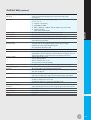
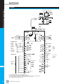
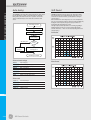
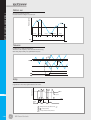
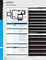
I/O terminal board specifications
Terminals
Function
Description
Control terminal board
Digital inputs
RY0, RY24
PSI1 ~ PSI5
EMS
RESET
Analogue inputs
RUN
FSV
FSI
AUX
Analogue outputs
COM
FM
AM
COM
P10
Digital outputs
RC, RA
FC, FA, FB
PS01
PS02
PS03
PS0E
Relay input common
Programmable inputs
Emergency stop
This is a common terminal for relay input signals specified below
These inputs can be arbitrarily set to any of input sequence functions
If EMS is ON while the VAT2000 is stopped, all operational commands are cancelles. If it is ON during operation,
the VAT2000 is led into stopping sequence (ramp down stop or coast-to-stop are available.
It is also possible to output this signal as a fault (FLT).
Fault reset
A faulty condotion is reset. With this signal, a fault status output (FLT LED, FAULT relay operation) is turned OFF
and operation becomes possible
Forward run
This is a command for forward run. Run/Reverse mode by permanent or pulse command can be selected
Voltage/Frequency
This is mainly used for setting frequency (speed). The maximum speed setting is available at 10V input.
This input is valid when VFS function is ON
Current/Frequency
This is mainly used for setting frequency (speed). The maximum speed setting is available at 20mA input.
This input is valid when IFS function is ON
Auxiliary input
This is mainly used for setting frequency (speed). The maximum speed setting is available at ±10V input.
This setting is valid when AUX function is ON
Analogue input common This is a common terminal for FSV, FSI and AUX signals
Frequency meter
This is a voltage output signal for a frequency meter. In a standard mode, a 10V output is available at the
maximum frequency. This output voltage can be adjusted to 0.2 to 2.0 times 10V (max. output is, however,
approximately 11V). Internal parameters other than those of frequency can also be output (C13-0, C14-0)
Ammeter
This is a voltage output signal for ammeter. In a standard arrangements, an output of 5V is available for the
rated current. This output voltage adjustment of 0.2 to 2.0 times of 5V is also available. Internal parameters
other than those of current can also be output
Analogue output common This is a common terminal for a frequency meter and ammeter
FSV source
This is a 10V source used when a potentiomenter is connected to the FSV input circuit
The potentiometer should be of 2W and 2k2Ω
RUN
FAULT
READY
Current detection
Frequency speed
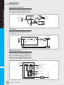
Open collector
output common
Dry relay contact assigned to RUN function as default. Programmable to other functions as well
Dry relay contact assigned to FAULT function. It operates when a fault occur
Programmable open collector output assigned to READY function as default
Programmable open collector output assigned to current detection function as default
Programmable open collector output assigned to speed detection as default attainment
This is a common terminals for the PS01, 2 and 3 outputs
All digital outputs can be set to any of output sequence functions
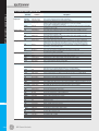
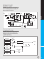
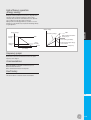
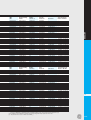
Input sequence functions
R RUN
Reverse run
F JOG, R JOG Forward/Reverse jogging
J
J.16
HOLD
BRAKE
C SEL
Hold
DC brake
Ramp selection
I PASS
VFS
IFS
AUX
PROG
CFS
S0 to S3, SE
Ratio interlock bypass
Speed setting 1
Speed setting 2
Speed setting 3
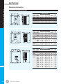
Program functions
CPU setting
Program setting
FUP
FDW
BUP
BDW
IVLM
AUXDV
PICK
EXC
ACR
PCTL
COP
LIM 1
LIM 2
CPASS
MCH
RF0
TRQB1
TRQB2
DROOP
DEDB
Frequency up
Frequency down
Bias up
Bias down
Bias ratio control
Dual settings
Pick-up
Pre-excitation
ACR
P control
CPU operation
Drive torque limiter
Regenerative torque lim.
Ramp bypass
MAchine time constant
0 setting
Torque bias 1
Torque bias 2
Drooping changeover
Dead band setting
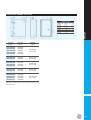
GE Power Controls
This is a command for reverse run
These are jogging commands. If this signal is ON while RUN is OFF, operation then conforms to the setting of
jogging (A00-1 or 3). For stopping, either ramp down stop or coast-stop is available
This is a stop signal used when Forward/Reverse command is operated by push-buttons
DC brake can be operated with this signal
Accel./decel. ramp performance is switched over. ACCel./Decel. time 2 (B10-0, 1) is available with ON,
and Accel./Decel. time 1 (A01-0, 1) is available with OFF
Ratio interlock operation is bypassed
Enables frequency (speed) setting from analog input FVS (C07-0)
Enables frequency (speed) setting from analog input IFS (C07-1)
Enables frequency (speed) setting from analog input AUX (C07-2)
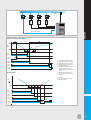
Used for multiple speed setting. Selection of up to 8 fixed speed (PROG0 ~ PROG7) is made with S0 ~ S3, SE
Enables frequency (speed) setting for a serial port
When PROG is ON, the program frequency (8 fixed speeds) (B11-0 up to 7) is enabled.
BCD or direct speed selection are allowed (B11-8)
Raises the output frequency or motor speed (A00-0, A00-2)
Decreases the output frequency or motor speed
Raises the output frequency set through PROG function
Decreases the output frequency set through PROG function
Enables BUP or BDW functions
Enables secondary settings (dual motor operation)
While this signal is ON, pick-up operation is effected as soon as RUN or R RUN is ON
Allows pre-excitation, establishing flux in the motor without generating torque
Enables ACR operation
ASR control is changed from the PI control to the P control
Enables command control from the serial port
The drive torque is limited by the analog input or serial transmission when enabled
The regenerative torque is limited by the analog input or serial transmission when enabled
The ramp function is bypassed when CPASS is enabled
Enables machine time constant compensation in ASR block
The speed setting is changed to 0 rpm.
The torque bias input 1 is enabled
The torque bias input 2 is enabled
Enables Drooping function (B13-5)
The dead band setting of ASR is enabled (B14-0)