1
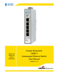
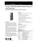
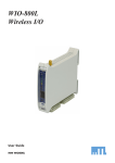
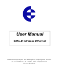
915U-2 Wireless Mesh Networking I/O & Gateway
Long Range, Scalable and Highly Resilient Multi I/O Node and Gateway
Applications
• Oil and Gas Production and
Distribution
• Pipeline Monitoring and Leak
Detection
• Pharmaceutical Monitoring and
Production
• Mining Operations Infrastructure
• Water Treatment Facilities
• Water & Wastewater Systems and
Treatment Facilities
Specifications
Transmitter/Receiver
Description
The ELPRO 915U-2 Wireless Mesh Networking I/O and Gateway is a multiple
I/O node that extends communications to sensors and actuators in local,
remote, or difficult to reach locations. Designed with a long range, licensefree 900MHz wireless transceiver, the ELPRO 915U-2 is capable of providing
IP-based mesh networking across sprawling industrial environments typical
of industrial applications.
Capable of ad-hoc mesh networking, roaming and discovery, as well as
deterministic mesh, the 915U-2 can serve as an end node, routing node
or network gateway. Scalable to thousands of nodes, Gather-ScatterTM
and Block Mapping technology offers the efficient utilization of network
resources, and eases integration into complex monitoring and control
systems. Integrated Modbus server capability allows further I/O expansion
through the use of ELPRO 115S Expansion modules.
Frequency
902 – 928MHz(1)
Transmit Power
1mW (+0dBm) to 1W (+30dBm)
Transmission
Frequency Hopping Spread Spectrum (FHSS)
Modulation
Frequency Shift Keying (FSK)
Receive Sensitivity
-109dBm @ 19.2kbps (3% FER)
Channel Spacing
50 x 250KHz(2)
Data Rate
19.2 – 115.2kbps(1)
“Auto Mode” selects fastest rate possible relative to RSSI
Range (LoS)
32Km (20 mi.) @ 1W(3)
Antenna Connector
1 x Female SMA Standard Polarity
Discrete Input
8 Digital I/O (1 – 4 Configurable as PI or PO)
On-State Voltage: <2.1Vdc
Wetting Current: 5mA
Max I/P Pulse Rate – DI 1/2: 50kHz, DI 3/4: 1kHz
Max I/P Pulse Width - DI 1/2: 10uSec, PI 3/4: 0.2mSec
Discrete Output
8 Digital I/O (1 – 4 Configurable as PI or PO)
On-State Voltage – DO Max: 30Vdc
Wetting Current – DO Max: 200mA
Max O/P Pulse Rate – PO Max Rate: 10kHz
Analog Inputs
4 AI (2 Differential, 2 Single Ended)
Current Range: 0 – 24mA
Current Resolution: 14 Bits
Accuracy (Current): 0.1%
Voltage Input Range: AI 1/2: 0 – 25V, AI 3/4: 0 – 5V
Voltage Resolution: 14 Bits
Accuracy (Voltage): 0.1%
Analog Output
2 AO (Sourcing)
Current Range: 0 – 24mA
Current Resolution: 13 Bits
Accuracy (Current): 0.1%
Input/Output
Features
• 902 – 928MHz Frequency up to 1W RF Power
• Frequency Hopping Spread Spectrum to 115kbps
• 50 x 250kHz Channels
• Self Healing IP-Based Wireless Mesh Networking
• Multi-Hop Repeater and Gateway Functionality
• Gather-ScatterTM and Block Mapping
• Serial Client/Server/Multicast Modbus TCP to RTU Gateway
• Configurable Digital, Pulse and Analog I/O to 14bit Resolution
• 10/100baseT IEEE 802.3 Ethernet
• Secure 128-bit AES Encryption
• Modbus RTU and TCP Support
• Over-The-Air Network Diagnostics and Configuration
Note: Specifications subject to change.
1) Country specific configuration
2) 18 New Zealand
3) Typical Maximum Line of Sight Range
Continued on back.
COMHAS SRL Via Matteotti, 66 20092 Cinisello Balsamo (MI) Tel. 02.6129.8551 Fax. 02.6659.4921
E-mail: [email protected] www.comhas.com
0212
BU-SB11855
Page 1 of 2
Data Sheet # 7923
915U-2 Wireless Mesh Networking I/O & Gateway
Long Range, Scalable and Highly Resilient Multi I/O Node and Gateway
Specifications
Ordering
Ethernet Port
To order, select product code from the table and specify country of application.
Ethernet Port
10/100baseT; RJ45 Connector – IEEE 802.3
Link Activity
Link, 100baseT via LED
Serial Port
EIA-562 (RJ45 Connector)
RS485
2-Pin Terminal Block – Non-Isolated(4)
Data Rate (Bps)
1200, 2400, 4800, 9600, 14400, 19200, 38400, 57600,
76800, 115200, 230400bps
Serial Settings
7 / 8 Data Bits; Stop/Start/Parity (Configurable)
Frequency
RF Power
915U-2
Wireless Mesh I/O
902-928MHz FSK
1W
Accessories
The following accessories can assist with compatibility when commissioning.
Product Code
Protocols and Configuration
System Address
ESSID; 1 – 31 Character Text String
Protocols Supported
TCP/IP, UDP, HTTP, FTP, TFTP, TELNET, MODBUS, MODBUS-TCP
User Configuration
All User Configurable Parameters via HTTPS
Security
Description
Note: Available RF power and frequency may vary depending on country of application.
RS232
Configurable
Parameters
Product Code
Unit details, I/O mappings and parameters, radio settings,
for more refer to user manual.
Modbus TCP/ RTU Gateway
Embedded Modbus Master/Slave for I/O transfer
Data Encryption – 128bit AES. Secure HTTP Protocol
LED Indication/Diagnostics
Description
Data
Sheet #
Interface
915U-TCP
Modbus TCP/RTU Gateway
7923
915U-TCADP
TCP Adaptor (Type T Thermocouple)
7930
DG900
Whip Antenna - SMA Male, angle bracket, -2dB gain,
1m (3’) coaxial cable
7942
WH900
Whip Antenna - SMA Male
7942
CFD890EL
Dipole Antenna - SMA Male, mounting bracket,
5m (16’) Coaxial cable
7942
Antennas - 900MHz
LED Indication
Power/OK; TX/RX; RS232; RS485; Digital I/O; Analog I/O status
Reported Diagnostics
RSSI Measurements (dBm), Connectivity Information/Statistics,
System Log file
SG900EL
Collinear Antenna - N-type Female, 5dB gain
7942
SG900-6
Collinear Antenna - N-type Female, 8dB gain
7942
Optional Network Management System
YU6-900
Yagi Antenna - N-type Female,10dB gain
7942
YU16-900
Yagi antenna - N-type Female, 15dB gain
7942
CC3/10/20-SMA
Coaxial Cable Kit - 3m (9.8’)/10m (32’)/20m (65’),
N-type to SMA
7932
CCTAIL-SMA-F/M
Coaxial Cable Tail - 600mm (24”), SMA to N-type
Female or Male
7932
ETH-C5A
Ethernet Cable - 1.8m (6’), direct, RJ45 to RJ45
7932
RS232 Serial Cable - DB9 Male to DB9 Female
7932
RS232 Serial Cable - DB9 Female to RJ45
7932
Network Management
Compliance
EMC
FCC Part 15; EN 301 489; AS 3548
RF (Radio)
FCC Part 15.247; AS 4268.2 ; RFS29 NZ
Hazardous Area
CSA Class I, Division 2; ATEX; IECEx Na IIC
Safety
IEC 60950 (RoHS Compliant)
UL
UL Listed
Cables
General
Size
180 x 150 x 35 mm (5.91” x 7.09” x 1.38”)
SER-DB9
Housing
IP20 Rated High Density Thermoplastic
SER-RJ45
Surge Diverters
Mounting
DIN Rail
Terminal Blocks
Removable; Max conductor 12AWG (2.5 mm2)
CSD-SMA-2500
SMA Surge Diverter for use with CC10, CC20 - SMA
7936
Temperature Rating
-40 to +60°C; -40 to +140°F
CSD-N-6000
Coaxial Surge Diverter, Bulkhead N Female to N Female
7936
Humidity Rating
0 – 99% RH Non-condensing
MA15/D/1/SI
Power Supply Surge Diverter, 110Vac/15A
7936
0.5kg (1.1lb).
IOP32D
Signal Surge Diverter, 2 x 2-wire/1 x 4-wire
7936
Weight
Power Supplies
Power Supply
15 to 30Vdc; Under/ Over Voltage Protection
PS-DINAC-12DC-OK
DIN Rail Power Supply, 100 - 250Vac, 12Vdc/2.5A
7935
Average Current Draw
220mA @ 12V (Idle), 110mA @ 24V (Idle)
PS-DINAC-24DC-OK
DIN Rail Power Supply, 100 - 250Vac, 24Vdc/2A
7935
Transmit Current Draw
500mA @ 12V (1W), 250mA @ 24V (1W)
BR-COL-KIT
Mounting Bracket Kit for Collinear Antenna
7933
BR-YAG-KIT
Mounting Bracket Kit for Yagi Antenna
7933
Nominal Supply
Mounting Brackets
Note: Specifications subject to change.
4) Maximum Distance 1200m (3937‘)
The only controlled copy of this Data Sheet is the electronic read-only version located on the Cooper Bussmann Network Drive. All other copies of this document are by definition uncontrolled. This bulletin is intended to clearly present comprehensive product data and provide technical information that will help the end user with design applications. Cooper Bussmann reserves the right, without notice, to change design or construction of any products and to discontinue or limit distribution of
any products. Cooper Bussmann also reserves the right to change or update, without notice, any technical information contained in this bulletin. Once a product has been selected, it should be tested by the user in all possible applications.
COMHAS SRL Via Matteotti, 66 20092 Cinisello Balsamo (MI) Tel. 02.6129.8551 Fax. 02.6659.4921
E-mail: [email protected] www.comhas.com
0212
BU-SB11855
Page 2 of 2
Data Sheet # 7923