1
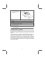
your hard disk drive. If it doesn’t, enter the Setup Utility and use the IDE Hard
Disk Auto Detect feature to configure the hard disk drive that you have installed. See IDE HDD Auto-Detection on page 27 for more information.
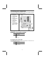
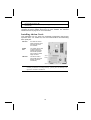
Installing a CD-ROM/DVD Drive
1.
2.
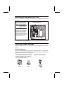
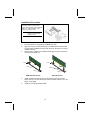
Install the CD-ROM/DVD drive into the drive cage in your system case.
Plug the IDE cable into IDE1
(A). If you have already installed
an HDD, use the other connector on the IDE cable.
Note: Ribbon cable connectors are
usually keyed so that they can only
be installed correctly on the device
connector. If the connector is not
keyed, make sure that you match the
pin-1 side of the cable connector with
the pin-1 side of the device connector. Each connector has the pin-1
side clearly marked. The pin-1 side of
each ribbon cable is always marked
with a colored stripe on the cable.
3. Plug an IDE cable connector into the CD-ROM/DVD drive IDE connector (B). It
doesn't matter which connector on the cable you use.
4. Plug a power cable from the case power supply into the power connector on
the CD-ROM/DVD drive (C).
5. Use the audio cable provided with the CD-ROM/DVD drive to connect to the
mainboard CD-in connector CDIN1 or CDIN2 (D).
When you first start up your system, the BIOS should automatically detect
your CD-ROM/DVD drive. If it doesn’t, enter the Setup Utility and configure
the CD-ROM/DVD drive that you have installed. See IDE Primary/Secondary
Master/Slave (Auto) on page 27 for more information.
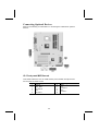
Installing a Floppy Diskette Drive
The mainboard has a floppy diskette drive (FDD) interface and ships with a
diskette drive ribbon cable that supports one or two floppy diskette drives. You
can install a 5.25-inch drive and a 3.5-inch drive with various capacities. The
floppy diskette drive cable has one type of connector for a 5.25-inch drive and
another type of connector for a 3.5-inch drive.
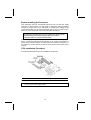
1.
2.
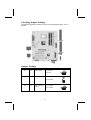
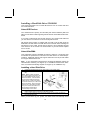
Install the FDD into the drive cage in your system case.
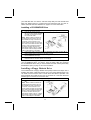
Plug the FDD cable into FDD1
(A):
Note: Ribbon cable connectors are
usually keyed so that they can only
be installed correctly on the device
connector. If the connector is not
keyed, make sure that you match the
pin-1 side of the cable connector with
the pin-1 side of the device connector. Each connector has the pin-1
side clearly marked. The pin-1 side of
each ribbon cable is always marked
with a colored stripe on the cable.
17