1
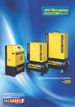
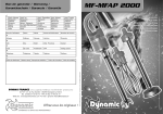
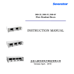
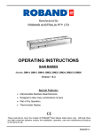
Gas rig user manual
BM26
Gas rig @ DUBBLE
Figure 1 Scheme of the whole installation
Abbreviations:
MFC – mass flow controller
BPC – back pressure controller
Operating procedure
Switching on the gas rig
i)
Switch on main power supply on the electrical box placed inside the experimental hutch.
The switch is mounted on the left hand side of the box. Turn red button ¼ clockwise into
the position ON. Wait few seconds to system to start.
ii)
Switch on compressed air which is needed for opening pneumatic valve.
iii)
Open vent valve
iv)
Restart the DUBBLE 15 computer even though the computer is already running
v)
Start ‘GAS RIG’ application. In the top left corner is icon called PORT, choose
‘COM1’. Wait few seconds for establishing digital communication between PC and
RS232 remote converter. Once the connection is established, it will appear on your
screen a picture as shown in Figure 2. If an error message ‘incorrect port’ appears on the
screen, restart again DUBBLE15 PC.
vi)
Once you connected gas cylinders: make sure that end of line ON/OFF valves are open
on the MFC panel and two valves on back pressure controller panel are in position
towards BPC.
vii)
Make sure two manual valves before exhaust are open
How to operate software while using only gases
Following establishing connection and double checking that everything is connected properly, you
can start typing in desirable value for a gas flow and pressure.
i)
Double clicking on MFCi (i = 1 – 6), it will pop up window as shown in appendix A,
where are displayed calibration curves for each MFC. Choose one calibration curve by
clicking on circle.
ii)
Click on red square below EVi (i = 1-6). This will result in changing a colour from red
to green. Red colour – pneumatic valve closed; green colour – pneumatic valve open.
Open only EVi valves which you will use.
iii)
Type in window above MFC desirable flow which must in the range stated in calibration
curve.
iv)
Keep hands off from clicking on buttons ‘heat off’!!!
v)
In a green window above BPC type desirable pressure between (0-50) bars.
vi)
EV10; EV7 and EV8 are fast switching valve. Clicking on them, you will change the
position of the valve (towards cell or towards vent). If you don’t use steam is highly
recommended to use only EV10. There is no need for you to use EV7 and EV8.
vii)
Click on a green process button.
Procedure for connecting bottles
i)
Purge lines which will be in use at least for 30 min with He or N2
ii)
In appendix A is a list of calibration curves inserted in each MFC according to a flow
rate and a gas. According to your experimental proposal select the MFC which is the
most suitable for your reaction process in terms of flow rate and type of a gas.
iii)
Go to the panel with pressure regulators in the corridor and look for a line with a
pressure regulator which refers to a selection of MFC in a step ii).
iv)
Connect a gas cylinder with correct bottle connector installed on flexible hose. The
stainless steel flexible hose are permanently connected to a gas panel. In order to change
a bottle connector disconnect fast connect adapter on a bottle connector.
v)
Make sure that pressure regulator is closed and upstream and downstream pressure set to
zero. If not, release the pressure by following procedure: Close pressure regulator and
slowly open vent valve. Once pressure is released, keep vent valve open and slowly
open pressure regulator in order to set upstream pressure to zero.
vi)
Open ON/OFF manual valve connecting flexible hose.
vii)
Open GENTLY valve on a gas cylinder.
viii)
Vent a gas cylinder couple of times as described in paragraph v) for pressure release
procedure.
ix)
Make sure that vent and purge valves are closed during a gas delivery to experimental
hutch.
x)
Make sure the end of line valve installed on the MFC panel in experimental hutch are
open for lines in use.
xi)
Once you finished you experiment purge all used line.
Figure 2 Screen shot of software after starting ‘Gas rig’ application
Appendix A
List of calibration curves inserted in each mass flow controller
Figure 3 Calibrations curves for MFC1
Figure 4 Calibration curves for MFC2
Figure 5 Calibration curves for MFC3
Figure 6 Calibration curves for MFC4
Figure 7 Calibration curves for MFC5
Figure 8 Calibration curve for MFC6