1
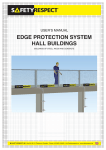
USER MANUAL
EDGE PROTECTION SYSTEM
STANDARD
INSTRUCTIONS IN ACCORDANCE WITH
EN 13374
[email protected] • Phone +46 (0)63-130400
CONTENTS
3. Safety precautions
4. Attachments
5. Socketbase
6. Clamps
8. Platform Bracket
9. Console Bracket
10. Vertical Bracket
10. Slab Edge Bracket
11. Beam Brackets
12. Barrier Brackets
13. Post
13. Ground Support and Base Plate
14. Barriers
16. Adjustable Link Bars
17. Flex System
19. Standing Seam Bracket
20. Checklist for mounting
CONTACT US
Phone:
Fax:
E-mail:
Web site:
+46 (0) 63-130400
+46 (0) 63-181319
[email protected]
www.safetyrespect.com
Mail:
SafetyRespect AB
Box 69
SE-831 21 Östersund
Sweden
2
Deliveries:
SafetyRespect AB
Jägarvallsvägen 19
Stadsdel Norr
SE-831 32 Östersund
Sweden
safetyrespect.se +46 (0)63-130400
SAFETY PRECAUTIONS
Risks when mounting
•
•
•
•
•
•
Falling
Dropping of tools
Dropping of components
Crushing
Injuries to eyes and ears
Incorrect mounting
Measures to minimise the risks
Always use personal fall protection when carrying out
mounting work.
• When mounting or dismounting, personal fall protection shall
always be used if there is a risk of falling. This also applies
when working from a claw crane, aerial platform, etc.
• We recommend using a painter connected to tools.
• Cordon off the area below and around the place of mounting
so that unauthorised people cannot be injured in case of
dropping, for instance, tools or material.
• Always use clothing and protective equipment dedicated for
the purpose.
• Always check the products and equipment before use.
• Do not use damaged material as it may influence the safety.
• Use tools dedicated for mounting.
Do not combine products of different brands
The fall protection is a system and should therefore
not be used with other products that are not allowed by
SafetyRespect. The product responsibility applies only to
SafetyRespect’s products and approved solutions.
+46 (0)63-130400 safetyrespect.se
3
ATTACHMENTS
CONCRETE SCREW
Drill holes that are 12 mm x 85 mm deep at least 120 mm from an
edge. Clear the hole from drilling residues. Make sure the bracket
is mounted so that the whole construction surface rests on the
foundation. Tighten screws, but not too much - Then the screw
might come loose.
CONCRETE WEDGE ANCHOR
Mounting should be done on
sufficiently hardened concrete only.
Drill a 20 mm hole that is at least 75
mm deep and 200 mm from the edge.
Clear the hole from drilling residues.
Mount wedge anchor M16. Then
mount the bracket and screw the bolt
to the wedge anchor.
WOOD SCREW
The wood should be of high quality, and preferably cross-glued
in order for it not to crack. Use wood screw, for example
WFD-T 12 x 100/70, when mounting. The screw should be
mounted at least 100 mm from the nearest edge. Tighten
screws and make sure the bracket is mounted so that the whole
construction surface rests on the foundation.
Characteristic extension loads:
• Concrete screw 12 x 75
• Wedge anchor M16
• Wood screw WFD 12 x 100/70
4
36.0 kN
31.8 kN
11.3 kN
safetyrespect.se +46 (0)63-130400
SOCKETBASE
Mount the Socketbase so that the whole
construction surface rests on the foundation.
Tighten screws/bolts so that the Socketbase
is butt against the foundation.
MOUNTING WITH
CONCRETE SCREW 12X75
See mounting instructions
on page 4.
MOUNTING WITH
WEDGE ANCHOR M16
See mounting instructions
on page 4.
OK!
NOT OK!
MOUNTING WITH
WOOD SCREW 12X100/70
See mounting instructions
on page 4.
+46 (0)63-130400 safetyrespect.se
5
CLAMPS
All clamp models should be mounted
according to the following structure:
Check that the clamp is mounted transversely to the mounting
surface (see picture below). Make certain to have as large a
mounting surface as possible. The clamp can be mounted both
horizontally and vertically. Protect sensitive surfaces that the
clamp may damage when tightened. Tighten so that the clamp is
properly fastened in a stable manner.
6
OK!
OK!
NOT OK!
NOT OK!
OK!
NOT OK!
safetyrespect.se +46 (0)63-130400
CLAMP 550
Clamp 550 can be mounted either in horizontal or vertical postition,
and in staircases. The Clamp can be mounted to the right or the left.
The gap can be adjusted from 20 mm up to 550 mm.
Make sure to tighten the clamp properly.
CLAMP 300
Clamp 300 can be mounted either in horizontal or vertical postition in
several situations. The socket can be attached in four different places
on the clamp. The gap can be adjusted from 10 mm up to 300 mm.
Make sure to tighten the clamp properly.
+46 (0)63-130400 safetyrespect.se
7
CONSOLE BRACKET
SafetyRespect Console Bracket is used when edge
protection must not interfere with the work surface or when
the distance between the slab edge and edge protection
requires adjustments.
The Console Bracket is used
combined with the Socket Base.
See information about attachments
and mounting on page 4.
0
15-50
M16 x 30
8
safetyrespect.se +46 (0)63-130400
PLATFORM BRACKET
Console Bracket (1) and Bracket Pin (2) are used together to
create the product Platform Bracket. This is intended to be used
as a plateau for wooden beam 45 x 195 mm (3) to create a
platform in shafts and openings.
MOUNTING
Drill holes for bracket pin Ø20
depth = 85 mm, consider edge
distance for drilling. Clear the
hole from drilling residues.
Install the Platform Bracket
in the hole and do the same
on the other side of the shaft
or opening. Cut the beam at
the correct length to lock the
Platform Bracket in both ends.
Oblique ends
appr. 2 degrees
Warning!
SafetyRespect only takes
responsibility for the Platform
Bracket meets the requirements
according to the prescribed
use and not for timber or other
details that may be included in
the overall construction.
Maximum load 1000 kg/Console
+46 (0)63-130400 safetyrespect.se
9
VERTICAL BRACKET
The Vertical Bracket is
used on facades, balconies
or slab edges. The vertical
bracket allows mounting
at the working level.
Alternative mounting
position is outside the
slab edge when there is
a need for access to the
slab edge. The bracket
has an integrated socket.
See information about
attachments on page 4.
SLAB EDGE BRACKET
See information about attachments and mounting on page 4.
10
safetyrespect.se +46 (0)63-130400
BEAM BRACKETS
Beam brackets are available
both for primary and secondary
beams. Beam brackets are
available for different beam
systems found in the market.
Make sure the brackets are
correctly mounted in a vertical
position and tightened properly.
+46 (0)63-130400 safetyrespect.se
Primary
Secondary
11
BARRIER BRACKETS
BARRIER BRACKET WEDGE COUPLER
Used with Barriers and Adj. Link Bars.
Mounted on 48,3 mm pipes and posts.
Make sure the brackets are tightened properly.
BARRIER BRACKET WEDGE COUPLER DUBBLE
Used with Barriers and Adj. Link Bars.
Mounted on 48,3 mm pipes and posts.
Make sure the brackets are tightened
properly.
12
safetyrespect.se +46 (0)63-130400
POST
1
2
3
Mount the post in the
socket and turn it at least
half a turn to activate the
post lock.
GROUND SUPPORT PLATE
Is used to protect sensitive surfaces or for building walk ways.
The Socket Base can be mounted at three different distances.
Nail or screw the ground support where possible
to fasten it properly.
+46 (0)63-130400 safetyrespect.se
13
BARRIERS
Place the Barrier on the
Barrier bracket and lock it
in a vertical position.
The Barriers shall always
be mounted towards the
working surface.
14
safetyrespect.se +46 (0)63-130400
The barrier’s side with a logotype should face towards the
posts. Continue building with brackets, posts and barrier.
The distance between the brackets should be a maximum
of 2.4 metres. Joint the barriers on the posts.
Max end without post 300 mm.
End of barrier
The free end of the barrier
may not exceed 300 mm.
Each barrier must be
supported by two posts.
+46 (0)63-130400 safetyrespect.se
15
ADJUSTABLE LINK BARS
Adjustable Link Bars are available in three different lengths and
each of these is adjustable. Mount Adjustable Link Bars onto the
brackets of the posts and lock them in vertical position.
Adjust the link bar and tighten the stop screw properly.
BARRIER BRACKET 360
Used to create flexible corners and
angels with Barriers and Link Bars.
16
safetyrespect.se +46 (0)63-130400
FLEX SYSTEM
FLEX FACADE BRACKET
Can be mounted on steel,
concrete and wood. Make
sure the mounting meets
the required extension load.
Adjust the post socket to
the working surface.
FLEX WORKING PLATFORM
< 1100
See user’s manual for
mounting instructions.
FLEX ROOF GABLE ATTACHMENT
1. Drill holes in the roof and mount the brackets. 2. Adjust to the
facade. 3. Adjust the post socket to the working surface.
+46 (0)63-130400 safetyrespect.se
17
FLEX EAVE BRACKET
Please see the separate user’s
manual for more information
and mounting instructions.
40
60
Ø13
60
45-150
120
18
safetyrespect.se +46 (0)63-130400
STANDING SEAM BRACKET
Standing Seam Brackets are used on sheet
metal roofing with double lock standing seam.
The roof must be in good condition and the
sheets well anchored to the underlay.
Mount the bracket over the standing seam
allowing the seam locks to grip under the
seam. Tighten the bolts. The bracket can
be adjusted to four positions for roof pitches
from 5 - 40°.
NOTE!
The bracket may only be subjected to forces
directed parallel to the sheet metal seam.
+46 (0)63-130400 safetyrespect.se
19
12 06 07
CHECKLIST FOR MOUNTING
Carry out a careful inspection of your mounting to make certain
that it has been done in accordance with the instructions. If you
have any questions, please contact SafetyRespect. Please use
the checklist below for inspection.
Checklist for mounting of fall protection
Check that:
More information at page:
1. The included components have been checked to ensure
that there is no damages.
3
2. Holes for bolts/wedge anchors have been drilled to the
proper depth and correct dimension, and that the distances
between the edges are according to the recommendations.
4
3. The attachment parts are tightened against the foundation
and that there is no looseness.
5
4. The posts are mounted and locked to the brackets.
The posts should be turned at least half a turn.
13
5. The barrier and link bars is correctly mounted on the
correct side of the posts.
14
6. The lower edge of the barrier is close to the foundation.
14
7. The barrier is locked with the railing lock.
14
8. The joints between the barriers are correct.
15
9. The free end of the barrier is a maximum of 300 mm.
15
10. Holes and openings are secured by using required safety straps.
Contact SafetyRespect:
+46 (0)63-130400 • [email protected] • www.safetyrespect.com
Quality-assured fall protection