1
SECOM 737CE
User Manual
Version 1.94/01
s c h e r m u l y
t e x t i l e
c o m p u t e r
User - Manual
SECOM 737CE
Copyright 2009 SETEX Schermuly textile computer GmbH
SETEX
Schermuly textile computer GmbH
Hauptstr. 23–25
35794 Mengerskirchen
Germany
Version 1.94/01 (date 15.01.2010).
The content of this user manual is subject to changes without notice.
This user manual may contain copyright information. No part of this manual should be copied or
duplicated without the written approval from SETEX.
Document number: 737CE-KEA-001-0194-1
Article number: SD2125001
2008
Schermuly textile computer
EG declaration of conformity
for the CE marking
Product (s)
Industrial PC
SECOM 737CE
If used as directed the indicated product is in line with the regulation of the following European
Directives:
93/68/EWG
Directive for CE Marking
89/336/EWG
Directive for Electromagnetic Compatibility (EMC)
73/23/EWG
Low Voltage Directive (LVD)
The conformity of the indicated product with the regulations of the above-mentioned directives is
proven by the compliance with the following harmonised standards:
Emitted Interference:
DIN EN 55022 (09/03), DIN EN 61000-6-4 (08/02)
Interference resistance:
DIN EN 61000-6-2 (08/02)
Security:
DIN EN 60950-1 (03/03)
Oliver Schermuly
Managing Director
for
SETEX Schermuly textile computer GmbH
Hauptstraße 23–25
35794 Mengerskirchen
Germany
Safety advices
General notice
Several icons are used in this manual to point out warnings,
possible errors and hints. The icons have the following
meanings:
Reference
This icon is used for general references.
Attention
Parts in the manual marked with this symbol refer to
possible error conditions or dangerous situations that might
occur when working with the controller.
Warning
This symbol is used to point out dangers for the user’s
health.
Safety advices
S-I
Safety advices
The operating instructions should be read carefully before
installing and setting the controller into operation. Wrong
handling can lead to injuries and/or damages of equipment.
The proper and safe function of the controllers requires a
correct transport and storage of the equipment as well as a
professional installation and maintenance.
In principle, electronic appliances are not fail-safe. The user
must take care that the machine is in a safe mode if a
failure on the controller occurs. Otherwise, this could cause
injuries to persons or damages to the equipment
When opening covers or removing parts from the controller,
parts connected to the supply voltage may be uncovered
and could be touched. Before working on it or exchanging
parts of the controller, if it becomes necessary to open the
controller’s housing, the controller must be disconnected
from power. Repairs of the controller which have to be done
while the housing is open while power is applied to the
controller, this must only be done by trained and qualified
personnel..
If one can assume that a safe operation is no longer
possible, the appliance must be switched off. Make sure
that it cannot be switched on accidentally in this case.
It can be assumed that a safe operation is no longer
possible in the following conditions,
− If there are visible damages on the controller,
− If the controller does not work,
− If the controller has been stored under inadequate
conditions for a longer period of time,
− After unsuitable transportation conditions.
S-II
Safety advices
Safety advices
1. General information
During operation, the SECOM controllers might have –
corresponding to their protection class – parts with live
voltages, hot surfaces or eventually moving parts.
There is a risk of injuries to persons and damages of the
equipment if the protective covers are opened, if the
controller is not properly installed or when operating errors
occur.
You will find more information on this subject in the
documentation.
All work in regard to the transport, the installation, the setting
into operation and the maintenance should be done by
authorized and qualified personnel only (the relevant IEC-,
DIN-, VDE- and national regulations for prevention of
accidents and electrical hazards must be observed).
Qualified personnel in this sense are persons who are
familiar with the installation, the mounting, the setting into
operation and the operation of the controller and who
possess the qualifications related to their profession.
2. Use of the controllers
The SECOM controllers are electrical equipment for the
installation in control cabinets of electrical facilities or
machines.
Please find the technical data and the information on the
connection of the controller in the documentation. These
instructions must strictly be observed.
3. Transport, storage
Please observe the advice for the transport, the storage and
the proper handling of the controllers.
4. Installation
The installation and measures for adequate air ventilation of
the controllers must be done in accordance with the
instructions in the related documentation.
Make sure that no components are bend during transport
and handling. Avoid touching the electrical components and
contacts.
Safety advices
S-III
Safety advices
5. Electrical connection
The electrical installation has to be done according to the
relevant regulations (e. g. wire cross section, fuse protection,
protective conductor connection etc.). Advice about this
matter is included in the documentation.
6. Operation
Production facilities with integrated computer controllers
must be equipped in certain cases with additional
supervising and protective equipment in accordance with the
relevant safety regulations, regulations for prevention of
accidents, etc.
The machine construction must include measures limiting
the consequences of a malfunction or a damage of the
controller in order to avoid injuries to persons or damages to
the equipment.
All covers and doors must be shut during the operation.
These safety instructions must be kept!
Please observe also the specific safety instructions and
the operating instructions.
S-IV
Safety advices
Table of contents
Chapter 1 ..................................................................................................... 1-1
INTRODUCTION
1-1
1 GENERAL INFORMATION ........................................................... 1-2
2 OPERATION ................................................................................. 1-3
2.1 OPERATING ELEMENTS .............................................................. 1-4
2.1.1 Program function keys ...................................................... 1-4
2.1.2 Special function keys / Hot keys (with LED)...................... 1-4
2.1.2.1
2.1.2.2
2.1.2.3
2.1.2.4
2.1.2.5
Lock key .............................................................................. 1-5
Alarm key ............................................................................ 1-6
Operator call key ................................................................. 1-6
Addition key......................................................................... 1-7
Manual operation key .......................................................... 1-7
2.1.3 Start-key ........................................................................... 1-8
2.1.4 Stop-key............................................................................ 1-8
2.1.5 Numeric keypad ................................................................ 1-8
2.1.6 Cursor keys ....................................................................... 1-8
2.1.7 Other function keys ........................................................... 1-9
2.2 DISPLAY ................................................................................. 1-10
2.2.1 Display layout ................................................................. 1-10
2.2.1.1
2.2.1.2
2.2.1.3
2.2.1.4
2.2.1.5
2.2.2
2.2.3
Status-line ......................................................................... 1-10
Program status .................................................................. 1-11
Process information........................................................... 1-12
Batch information window .................................................. 1-12
Program function key line .................................................. 1-13
Message windows........................................................... 1-17
Startup screen ................................................................ 1-18
Chapter 2 ................................................................................................... 2-19
EDITING PROGRAMS
2-19
3 BASIC INFORMATION ............................................................... 2-21
3.1 PROGRAM STRUCTURE ............................................................ 2-21
3.1.1 Functions ........................................................................ 2-21
3.1.1.1 Main functions ................................................................... 2-22
3.1.1.1.1 System functions .......................................................... 2-23
3.1.1.2 Parallel functions ............................................................... 2-25
4 CREATING A PROGRAM .......................................................... 2-26
4.1 ENTERING THE PROGRAM HEADER ............................................ 2-27
4.2 ENTERING PROGRAM STEPS ..................................................... 2-28
4.2.1 Programming main functions .......................................... 2-29
4.2.2 Programming parallel functions ...................................... 2-33
4.2.2.1
4.3
4.4
More than 8 parallel function groups.................................. 2-34
SAVING PROGRAM STEPS ......................................................... 2-35
SAVING PROGRAMS ................................................................. 2-35
737CE/1.94/01
Table of contents
i
Table of contents
5 MODIFYING PROGRAMS .......................................................... 2-36
5.1 SELECTING A PROGRAM ........................................................... 2-37
5.2 CHANGING PROGRAM NAMES AND COMMENTS............................ 2-38
5.3 MODIFYING A PROGRAM STEP ................................................... 2-39
5.3.1 Modifying the main function parameters ......................... 2-40
5.3.2 Exchange/delete main functions ..................................... 2-40
5.3.3 Edit parallel functions ...................................................... 2-40
5.3.3.1
5.3.3.2
5.3.3.3
5.4
5.5
Change parameters of parallel functions ........................... 2-41
Delete parallel functions .................................................... 2-41
Program new parallel functions ......................................... 2-41
INSERTING A PROGRAM STEP .................................................... 2-42
DELETING A PROGRAM STEP ..................................................... 2-43
6 COPYING A PROGRAM ............................................................. 2-44
6.1 COPYING A PROGRAM ON THE CONTROLLER .............................. 2-45
6.2 COPY TO AN EXTERNAL DRIVE .................................................. 2-47
6.2.1 Copy via USB (USB memory sticks) ............................... 2-47
6.2.2 Copy via the network (host operation) ............................ 2-49
6.3 COPYING ALL PROGRAMS (BACKUP) .......................................... 2-49
6.4 COPY MESSAGES .................................................................... 2-50
7 DELETING A PROGRAM ........................................................... 2-51
8 ADDITION TREATMENT ............................................................ 2-53
8.1
8.2
8.3
8.4
MARKING THE ADDITIONS ......................................................... 2-53
PROGRAM STRUCTURE OF ADDITION TREATMENTS ..................... 2-54
CREATING AN ADDITION TREATMENT ......................................... 2-54
DEFINING ADDITION TEXTS ....................................................... 2-56
9 VARIABLE FUNCTION PARAMETER ....................................... 2-57
9.1
9.2
DEFINITION OF VARIABLE FUNCTION PARAMETERS / FORMULAS .... 2-57
EDITING VARIABLE FUNCTION PARAMETERS ............................... 2-58
Chapter 3 ................................................................................................... 3-61
OPERATION
3-61
10 STARTING A BATCH ................................................................. 3-63
10.1 GENERAL INFORMATION ........................................................... 3-63
10.2 OPENING THE BATCH CREATION WINDOW ................................... 3-64
10.3 PROGRAM SELECTION .............................................................. 3-65
10.3.1 Selection list .................................................................... 3-65
10.3.2 Entering the program number ......................................... 3-66
10.4 EDITING BATCH INFORMATION ................................................... 3-67
10.4.1 Entering batch texts ........................................................ 3-67
10.4.2 Entering batch parameters.............................................. 3-68
10.5 BATCH PROGRAM GENERATION ................................................. 3-69
10.6 STARTING THE PROGRAM ......................................................... 3-70
10.6.1 Possible errors when starting the program ..................... 3-70
10.7 BATCH LIST ............................................................................. 3-71
10.7.1 Loading an OrgaTEX batch ............................................ 3-73
ii
Table of contents
737CE/1.94/01
Table of contents
11 THE PROGRAM IS RUNNING.................................................... 3-74
11.1 DISPLAY STATUS LINE .............................................................. 3-74
11.2 DISPLAY OF FUNCTIONS ........................................................... 3-74
11.2.1 Display of actual values .................................................. 3-74
11.2.2 Main functions ................................................................. 3-75
11.2.3 Parallel functions ............................................................ 3-75
11.2.3.1 Display of parallel function parameters .............................. 3-76
11.3 MANUAL INTERVENTION ........................................................... 3-77
11.3.1 Manual intervention by pressing the hot key ................... 3-77
11.3.1.1
11.3.1.2
11.3.1.3
11.3.1.4
Changing the actual main function and its parameters ...... 3-78
Changing the parallel functions and their parameters ........ 3-78
Return to the automatic mode ........................................... 3-79
Changing the program steps ............................................. 3-79
11.3.2 Some explanations ......................................................... 3-80
11.4 DISPLAY OF OPERATOR CALLS .................................................. 3-81
11.4.1 Operator call “Sample” .................................................... 3-81
11.4.1.1
11.4.1.2
11.4.1.3
11.4.1.4
Sample is O.K. .................................................................. 3-81
An addition is required ....................................................... 3-82
Possible errors .................................................................. 3-83
Select a certain step for an addition .................................. 3-84
11.5 PROGRAM END ........................................................................ 3-84
12 INTERRUPTING A PROGRAM .................................................. 3-85
12.1
12.2
12.3
12.4
PRESSING THE STOP BUTTON ................................................... 3-85
STOP-ALARM .......................................................................... 3-85
POWER FAILURE ...................................................................... 3-86
RESTARTING THE PROGRAM ..................................................... 3-86
13 MANUAL OPERATION MODE ................................................... 3-88
13.1 CONDITIONS ........................................................................... 3-88
13.2 HOW TO ACTIVATE THE MANUAL OPERATION MODE? ................... 3-88
13.3 HOW TO LEAVE THE MANUAL OPERATION MODE? ........................ 3-89
Chapter 4 ................................................................................................... 4-91
BATCH INFORMATION
4-91
14 INFO-MENU ................................................................................ 4-92
14.1 PROCESS INFORMATION ........................................................... 4-92
14.2 ALARM LIST............................................................................. 4-93
14.3 EVENT LIST ............................................................................. 4-95
14.4 HISTORY ................................................................................ 4-96
14.4.1 Batch selection ............................................................... 4-97
14.4.2 Display of process values ............................................... 4-97
14.4.3 Copy historical batch data............................................. 4-100
14.4.3.1 Only one batch ................................................................ 4-100
14.4.3.2 All batches....................................................................... 4-101
14.5 PROGRAM LIST ...................................................................... 4-102
14.6 BATCH INFO .......................................................................... 4-104
737CE/1.94/01
Table of contents
iii
Table of contents
Chapter 5 ................................................................................................. 5-105
MESSAGES
5-105
15 ALARMS ................................................................................... 5-106
15.1 ALARM DISPLAY ..................................................................... 5-106
15.1.1 Alarm list ....................................................................... 5-108
15.2 STARTING THE CONTROLLER AFTER ALARMS OCCURRED ........... 5-110
15.2.1 Start the controller after a stop alarm ............................ 5-110
15.2.2 Start the controller after a hold alarm ............................ 5-110
15.3 ALARM CLASSIFICATION ......................................................... 5-111
15.3.1 User alarms .................................................................. 5-111
15.3.2 Controller and measurement system alarms ................ 5-111
15.3.3 System alarms of the SECOM ...................................... 5-112
15.3.4 System alarms of the PLC ............................................ 5-117
iv
Table of contents
737CE/1.94/01
Chapter 1
Introduction
1 GENERAL INFORMATION ........................................................... 1-2
2 OPERATION ................................................................................. 1-3
2.1 OPERATING ELEMENTS .............................................................. 1-4
2.1.1 Program function keys ...................................................... 1-4
2.1.2 Special function keys / Hot keys (with LED)...................... 1-4
2.1.2.1
2.1.2.2
2.1.2.3
2.1.2.4
2.1.2.5
Lock key .............................................................................. 1-5
Alarm key ............................................................................ 1-6
Operator call key ................................................................. 1-6
Addition key......................................................................... 1-7
Manual operation key .......................................................... 1-7
2.1.3 Start-key ........................................................................... 1-8
2.1.4 Stop-key............................................................................ 1-8
2.1.5 Numeric keypad ................................................................ 1-8
2.1.6 Cursor keys ....................................................................... 1-8
2.1.7 Other function keys ........................................................... 1-9
2.2 DISPLAY ................................................................................. 1-10
2.2.1 Display layout ................................................................. 1-10
2.2.1.1
2.2.1.2
2.2.1.3
2.2.1.4
2.2.1.5
2.2.2
2.2.3
737CE/1.94/01
Status-line ......................................................................... 1-10
Program status .................................................................. 1-11
Process information........................................................... 1-12
Batch information window .................................................. 1-12
Program function key line .................................................. 1-13
Message windows........................................................... 1-17
Startup screen ................................................................ 1-18
Introduction
1-1
Chapter 1
1 General information
Features
The program controller SECOM is an industrial PC designed and developed for
applications in the textile-finishing field.
The most important feature for the operator is the graphical user interface using
Windows CE. It allows the user to get acquainted with the system in a fast and
comfortable way.
The SECOM can be used as a single program controller as well as in a PC network.
Application
The main field of operation for the SECOM is the automation of all discontinuous,
program-controlled processes in a dye house.
Due to its flexibility and the possibility to be adapted to various systems, the program
controller can be applied to all production and laboratory facilities of wet finishing, like
e. g:
Jet
Jigger
Beam machine
Yarn machine
Foulard
Safety concept
Programs installed on the SECOM can be saved on a USB memory stick and can be
transferred to other machines or, if necessary, copied back to the controller.
The important machine related information stored on the SECOM like:
•
Machine functions
•
Configuration
are saved on a CompactFlash disk which is plugged into the SECOM.
The safety concept of the controller includes a power-fail recognition, which ensures
that the SECOM will be in a safe mode in case of power failure.
After restarting the controller the SECOM automatically returns to the interrupted
program step and can be restarted at that point.
Alarm processing
Failures that occur during the operation of the SECOM are announced by a displayed
text and are recorded at the same time.
Depending on the severity of the failure, the alarms may stop or interrupt the running
process.
There are different alarms announcing different failures:
1-2
•
Machine specific alarms
•
System alarms of SECOM
•
System alarms of the connected PLCs
Introduction
737CE/1.94/01
Introduction
2 Operation
Due to the various possibilities offered by a PC based controller, the operation of the
SECOM is very easy and is achieved by using only a few operating elements.
At the bottom of the screen the current available functions of the 4 function keys (F1 to
F4) are displayed.
Below the function keys you can find additional keys, so-called “Hot-Keys”. They are
used to open certain windows directly or to start certain actions.
Further below to the left there is the numerical keyboard. To the right you find keys to
start and stop the controller, cursor keys, page-up and page-down keys as well as
ESC, Alt, backspace and OK (Enter) keys which functions are similar to those on a
normal PC.
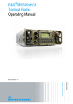
On the left side of the SECOM you will find a USB port that can be used for USB
memory sticks, keyboards etc. A cover closes it.
SECOM 737CE
Picture 2-1:
Front view
USB connector
737CE/1.94/01
Introduction
1-3
Chapter 1
2.1 Operating elements
2.1.1 Program function keys
The keys F1 to F4 are not fixed assigned to special program functions.
Picture 2-2: Example
program- function
key line
The current functions of each of these four keys are displayed in the lower part of the
screen (function key line).
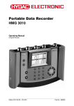
2.1.2 Special function keys / Hot keys (with LED)
Picture 2-3: Special
function keys (Hot
Keys)
With the help of the special function keys it is possible to open certain windows
directly or to start certain program actions.
1-4
Introduction
737CE/1.94/01
Introduction
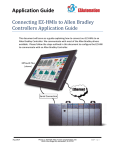
2.1.2.1 Lock key
Setting up different authorization level can restrict the access to different operations,
like e.g. program editor, manual operation or the configuration menu.
To get access to the different authorization levels, a pass-code must be entered after
pressing the lock key.
After the lock key is pressed, a window is displayed in which the pass-code has to be
entered.
Picture 2-4: Window
for pass-code input
After having entered the
numeric code (max. 8 digits)
and after having confirmed the
input with the OK key, the
window will be closed and
access to the corresponding
level is granted.
The code entered is displayed
as ********.
A yellow LED in the lock key
indicates that the program lock
has been opened.
In case you do not wish to enter a pass-code, the window can be closed by pressing
the Esc key.
If the lock key is pressed again, the access rights to the selected level will be
removed.
The yellow LED is switched off.
In case that a wrong pass-code has been entered the following message will be
shown.
Picture 2-5:Wrong
code
After pressing the OK key, this window will be closed and the pass-code can be
entered again.
737CE/1.94/01
Introduction
1-5
Chapter 1
2.1.2.2 Alarm key
The red LED is flashing when a stop alarm occurs.
The red LED is on when an info alarm or a hold alarm occurs.
Press the alarm key to close the alarm window and to quit the alarm.
See also chapter 5, item 15.1 Alarm display, on page 5-106.
If the alarm key is pressed in the main or in a selection menu, the alarm list will be
displayed (this is the Hot key for the alarm list of the info menu).
See also chapter 4, item 14.2 Alarm list, on page 4 -93.
2.1.2.3 Operator call key
The yellow LED is flashing when an operator call occurs.
This key has different functions depending on the current controller mode:
• If the operator call window is active:
The operator call will be confirmed.
• If a function stop (like e. g. load/unload, chemicals, color, sample) is active:
The function or the step is confirmed, provided that the step confirmation has been
initiated and the system constant no. 47 ”mode operator call key” is set to 1.
• If the controller is in any other state like than the two described above and if it is in
the main menu, in a selection menu or in the alarm list:
The process picture No. 9 will be displayed provided that it has been configured.
As per definition, this process picture should contain time- and batch information
for the operator.
(see chapter 4, Picture 14-3, on page 4-93
1-6
Introduction
737CE/1.94/01
Introduction
2.1.2.4 Addition key
The yellow LED is flashing if the controller is in ”RUN” mode and in function
”SAMPLE”, and provided that the addition selection has been enabled.
The yellow LED is on while the addition function is running (if the addition is finished
it jumps back to the sample step it came from) and is switched off as soon as the
sample function has been confirmed.
This key has different functions depending on the current controller mode:
• If the operator call window is active:
The operator call will be confirmed.
• Function ”Sample” is active:
When pressing the addition key, the window for the addition selection will be
displayed (this is the Hot key for the addition selection).
See also chapter 3, item 11.4.1.2 An addition is required, on page 3-82.
If the system constant 28, addition key, is set to 1 and the controller is in any other
state as mentioned above, then the extended program list will be shown if the button is
pressed.
2.1.2.5 Manual operation key
During manual operation, the yellow LED is flashing.
After pressing this key, the window with the manual operation editor will be displayed
(this is the Hot key for manual operation).
See also chapter 3, item 11.3.1 Manual intervention , on page 3-77.
737CE/1.94/01
Introduction
1-7
Chapter 1
2.1.3 Start-key
Press the green start key to start a selected program or to continue an interrupted
program.
”RUN” is displayed in the status line and the green LED is on.
2.1.4 Stop-key
Press the red stop key to interrupt the running program.
“BREAK” is displayed in the status line. The green start key LED is off.
2.1.5 Numeric keypad
The numeric keys are used to enter the numbers when
editing programs.
Picture 2-6: Numeric
keypad
The numeric keys can also be used as a shortcut to
select function groups and functions during
programming as well as to open an info window of the
parallel functions from the main menu.
2.1.6 Cursor keys
Picture 2-7:
Cursor keys
The cursor keys are used to select an element in a
selection window.
Within a list window, these keys are used to scroll up
or down line by line.
If the main window is shown and the controller is in the “STOP” state then the cursor
keys can be used to scroll through the program step by step.
1-8
Introduction
737CE/1.94/01
Introduction
2.1.7 Other function keys
Esc-key
Press the ”Esc” key to cancel your entries or to close open windows.
Backspace (delete) key
In an active input field, characters and numbers can be deleted one by one by
pressing the ”Backspace” key.
Alt-key
This key is used to open various windows.
OK key
This key has the same function as ”Enter” key of a standard PC.
Any input into a programmable field has to be confirmed by pressing OK.
If you are in a selection or list window you have to press the OK key to confirm the
selection made with the cursor keys.
737CE/1.94/01
Introduction
1-9
Chapter 1
2.2 Display
The LCD-screen works in VGA mode with a resolution 640x480 pixel and 256 colors.
2.2.1 Display layout
Picture 2-8:Main
menu
The display content is composed from a status line, function key information and
areas for the function display, step list and batch process information.
Depending on the situation additional windows will be opened and messages will be
shown. Also the operator can open other pictures, lists and information windows.
2.2.1.1 Status-line
Picture 2-9: Example
Status line
This line includes the following information from left to right:
• Temperature symbol (can also be configured to show other symbols/icons)
• Actual temperature value of the main tank (can also be configured to show
other values)
• Time symbol (can also be configured to show other symbols/icons)
• Remaining time for the current main function if applicable (can also be
configured to show other values)
1-10
Introduction
737CE/1.94/01
Introduction
• Program name of the actual running program or alarm number and total
number of all active alarms (if any)
• Status of the controller/dye process
• Program No. of the actual running or of the last running program
• Actual program-step number
If an alarm is active the alarm number will be shown.
Alarm display
Picture 2-10:
Example Alarm
display
If more than one alarm is active, the alarm number with the highest priority will be
displayed and the total number of all active alarms is shown.
Picture 2-11:
Example Alarm
display
2.2.1.2 Program status
The controller can be in one of the following states:
• SELECT
⇒
No batch (program) has been selected
• READY
⇒
A batch (program) is selected but has not been started yet
• RUN
⇒
A batch (program) is running
• BREAK
⇒
A batch (program) is interrupted (by stop key or stop alarm)
• END
⇒
A batch (program) has been finished
• HOLD
⇒
A batch (program) is on hold (hold alarm)
• INTERVENT
⇒
Manual intervention is active
• MANUAL
⇒
Manual operation mode is active, controller in STOP mode
• MAN ACTIVE ⇒
737CE/1.94/01
Manual operation mode is active, controller in RUN mode
Introduction
1-11
Chapter 1
2.2.1.3 Process information
The middle part of the screen shows information about the actual running program
respectively of the actual running batch and of the dye process in general. This part of
the screen is divided into four sections.
The upper left section shows the active main and parallel functions with the related
icons. For the main function the function set and actual parameters are shown. For the
parallel functions the set values are shown. By pressing the related numerical key a
window is opened that shows the set as well as the actual parameters of the parallel
functions.
Picture 2-12:
Function display,
main and parallel
functions
The middle right section shows the step list of the dye program from the actual batch.
The actual processed step is marked with a blue line. Selecting the program list with
the cursor keys followed by the OK key will open a larger, more detailed list screen.
Picture 2-13:
Display of the step
list, step 3 is active
2.2.1.4 Batch information window
The batch information window can optionally be configured to show batch information,
time information and process information etc. of the actual running batch.
Picture 2-14: Batch
information window
1-12
Introduction
737CE/1.94/01
Introduction
2.2.1.5 Program function key line
Located in the lower part of the screen is the function key line. Via the keys certain
program functions can be started or menus can be opened.
Picture 2-15: Example
program function key
line
The actual valid function for the keys F1...F4 is displayed program controlled in the
function key line.
Picture 2-16:
Example for an
opened menu
The functionality of the function keys as well as the contents of the menus can be
different according to the state of the controller.
The various menu entries can be selected via the cursor keys followed by pressing
OK.
On the following page you will find an overview over the menu structure and the menu
items.
737CE/1.94/01
Introduction
1-13
Chapter 1
1-14
Introduction
737CE/1.94/01
Introduction
737CE/1.94/01
Introduction
1-15
Chapter 1
1-16
Introduction
737CE/1.94/01
Introduction
2.2.2 Message windows
Message windows are displayed on the SECOM providing information and guidance
for the user. They point out different events or necessary steps to be taken. Each
message window includes a message text as well as an icon. The icon shows the kind
of displayed message.
The following information is shown in the message windows:
• Inquiries
Inquiries are mostly used for the interactive user guidance, to guide the user step
by step through the necessary measures or to point out different possible
measures to be taken. Messages, which include an inquiry, are marked with a
question mark (general inquiries) or an exclamation mark (safety inquiries).
• Process messages
Process messages are generated by the PLC program and include certain
information for the user, like e. g. ”Color kitchen ready”. Process messages are
marked with the caution sign. In addition, the number of the process message is
shown as well.
• Alarms
Alarm messages point out errors or faults within the process or within the system.
There are 3 different kinds of alarms.
1. Info alarms
2. Hold alarms
3. Stop alarms
Info and hold alarms, like e.g. ”Motor protection addition tank pump” are marked
with a warning sign. A stop alarm, like e.g. ”PLC communication error” is marked
with a stop sign. The alarm number as well as the alarm text is shown.
• Error messages
Error messages of the system software point out illegal actions or malfunctions
within the system, like e.g. ”Program not found”. These messages are marked with
a caution sign.
737CE/1.94/01
Introduction
1-17
Chapter 1
2.2.3 Startup screen
After the SECOM is switched on and Windows CE is started the startup screen is
shown during the initialization of the SECOM application software.
Depending on the supplier of the controller, the screen may look different.
Picture 2-17:
Example of a startup screen
After the application software is running the screen changes to the main window
automatically.
1-18
Introduction
737CE/1.94/01
Chapter 2
Editing programs
3 BASIC INFORMATION ............................................................... 2-21
3.1 PROGRAM STRUCTURE ............................................................ 2-21
3.1.1 Functions ........................................................................ 2-21
3.1.1.1 Main functions ................................................................... 2-22
3.1.1.1.1 System functions .......................................................... 2-23
3.1.1.2 Parallel functions ............................................................... 2-25
4 CREATING A PROGRAM .......................................................... 2-26
4.1 ENTERING THE PROGRAM HEADER ............................................ 2-27
4.2 ENTERING PROGRAM STEPS ..................................................... 2-28
4.2.1 Programming main functions .......................................... 2-29
4.2.2 Programming parallel functions ...................................... 2-33
4.2.2.1
4.3
4.4
More than 8 parallel function groups.................................. 2-34
SAVING PROGRAM STEPS ......................................................... 2-35
SAVING PROGRAMS ................................................................. 2-35
5 MODIFYING PROGRAMS .......................................................... 2-36
5.1 SELECTING A PROGRAM ........................................................... 2-37
5.2 CHANGING PROGRAM NAMES AND COMMENTS............................ 2-38
5.3 MODIFYING A PROGRAM STEP ................................................... 2-39
5.3.1 Modifying the main function parameters ......................... 2-40
5.3.2 Exchange/delete main functions ..................................... 2-40
5.3.3 Edit parallel functions ...................................................... 2-40
5.3.3.1
5.3.3.2
5.3.3.3
5.4
5.5
Change parameters of parallel functions ........................... 2-41
Delete parallel functions .................................................... 2-41
Program new parallel functions ......................................... 2-41
INSERTING A PROGRAM STEP .................................................... 2-42
DELETING A PROGRAM STEP ..................................................... 2-43
6 COPYING A PROGRAM ............................................................. 2-44
6.1 COPYING A PROGRAM ON THE CONTROLLER .............................. 2-45
6.2 COPY TO AN EXTERNAL DRIVE .................................................. 2-47
6.2.1 Copy via USB (USB memory sticks) ............................... 2-47
6.2.2 Copy via the network (host operation) ............................ 2-49
737CE/1.94/01
Editing programs
2-19
Chapter 2
6.3
6.4
COPYING ALL PROGRAMS (BACKUP) .......................................... 2-49
COPY MESSAGES .................................................................... 2-50
7 DELETING A PROGRAM ........................................................... 2-51
8 ADDITION TREATMENT ............................................................ 2-53
8.1
8.2
8.3
8.4
MARKING THE ADDITIONS ......................................................... 2-53
PROGRAM STRUCTURE OF ADDITION TREATMENTS ..................... 2-54
CREATING AN ADDITION TREATMENT ......................................... 2-54
DEFINING ADDITION TEXTS ....................................................... 2-56
9 VARIABLE FUNCTION PARAMETER ....................................... 2-57
9.1
9.2
2-20
DEFINITION OF VARIABLE FUNCTION PARAMETERS / FORMULAS .... 2-57
EDITING VARIABLE FUNCTION PARAMETERS ............................... 2-58
Editing programs
737CE/1.94/01
Editing programs
3 Basic information
3.1 Program structure
Programs, which are edited and run on a controller, consist of a program header and
sequential program steps.
For program administration so-called header information data is required for each
program.
This information includes:
• Program number
• Program name
• Comments
• Date of creation
• Date of last change
• Number of steps
Each program step consists of a main function and up to 12 parallel functions.
The main functions control the main process, i.e. related to the main tank of the dyeing
machine.
The peripheral equipment of the machine, like preparation tank, addition tanks, color
kitchen tanks, pumps etc., are controlled by the parallel functions.
3.1.1 Functions
The SECOM offers a function range that suits all kind of dyeing machines.
Each function has a specific function name, function graphics and several parameters.
All functions of a specific type (like rinsing) are grouped together for an easy
reference.
737CE/1.94/01
Editing programs
2-21
Chapter 2
3.1.1.1 Main functions
The main functions control the processes, which are directly related to the dyeing
machine.
All machine functions of the same type are grouped together in main function groups.
Each function group includes a function group text and an icon.
Main function
groups
The following main functions are included in the standard configuration:
•
System
•
Filling
•
Rinsing
•
Draining
•
Dosing/inject Add1
•
Dosing/inject Add2
•
Operator Call
•
Dyeing
You will find a detailed description of all the functions in a separate list.
Assignment of
main functions
During the project work for your machine, the required main function groups are
selected. If necessary, new groups can be added. A maximum of 8 functions can be
assigned to each group.
Only the functions that have been selected will be visible during the programming and
the production process.
2-22
Editing programs
737CE/1.94/01
Editing programs
3.1.1.1.1 System functions
Among the main functions, the systems functions have a special purpose.
These functions do not control the machine but are used to trigger certain actions in
the SECOM.
The following system functions are implemented in the SECOM:
Program-start
This function must be programmed in the first program step.
The program start function initializes the controller in order to start a new batch.
After the program is started, the function is confirmed automatically by the PLC and
the program advances to the next step.
Program-end
This function must be programmed in the last program step.
The program end function stops the program and the mode of the controller changes
to “END”.
After that it is not possible anymore to start the program of the current batch again.
No operation
This function is needed when a step consists of parallel functions only and does not
include any main function.
The step confirmation then depends on the programmed parallel functions.
Addition start
This function marks an addition start within a program.
Each addition must be started with this function.
When an addition is started, this function will automatically be confirmed and the
program advances to the next step.
Addition end
This function is programmed at the end of an addition.
Each addition must be finished with this function.
When an addition is processed and reaches addition end, the function will
automatically be confirmed and the program returns to the “SAMPLE” step it came
from.
737CE/1.94/01
Editing programs
2-23
Chapter 2
Jump
This function is used to skip parts of the program or to program a loop. A label function
is used as a target to jump to. When the program reaches the function ”Jump”, the
process will be continued at the programmed label.
There is no automatic return!
Label
This function marks the target of the program jump. A maximum of 100 jump labels
can be defined.
2-24
Editing programs
737CE/1.94/01
Editing programs
3.1.1.2 Parallel functions
The SECOM provides a parallel function group for each peripheral equipment, like e.g.
addition tanks, preparation tank, dye kitchen tank, etc.
Like the main functions all parallel functions of the same type are combined in function
groups.
For each group there is a function group text and an icon.
The standard configuration for a jet for instance provides the following parallel function
groups:
•
Pump
•
Material flow
•
Addition tank 1
•
Addition tank 2
Parallel function
groups
You will find a detailed description of these functions in a separate function list.
During the project work for your machine the required parallel function groups are
selected. If necessary, new groups can be added. A maximum of 12 parallel function
groups can be programmed.
Assignment of
parallel functions
Up to 8 parallel functions can be assigned to each function group.
Only these functions are visible during the programming and the production process.
737CE/1.94/01
Editing programs
2-25
Chapter 2
4 Creating a program
A program can be created while a batch is running or if the controller is in the stop
mode.
Picture 4-1: Main
menu
To avoid that every operator can invoke the program editor, the SECOM offers the
possibility to lock this function with a pass-code.
If the default access is not set at least to level 4 (”Edit”), the operator only gets access
to this function by entering the correct pass-code.
After pressing the lock key, the controller opens a window and you must enter the
code. A yellow LED indicates that access to the corresponding level has been
granted.
Press key “PROGRAM” (F4) in the main window.
A selection menu appears.
Picture 4-2: Program
action window
With the cursor keys select line “New”.
A window to enter the program header data will be
shown.
2-26
Editing programs
737CE/1.94/01
Editing programs
4.1 Entering the program header
A program header is automatically generated for each new program. Accessible for
the operator are the fields for the program number, the program name and the
comments.
A number (maximum 4 digits) must be assigned to each program. By default the
controller shows the lowest free number (can be changed). This number is the main
key for the program administration.
Setting up the
program number
Picture 4-3: Program
header window
Confirm the number or enter a new one.
Each program can have a name with a maximum of 20 characters. Thus, the operator
has the possibility to enter meaningful program names distinguishing similar programs
one from another.
After having entered the program number the window for the input of the program
name is displayed. Use the cursor keys and/or the numerical keypad to select the
required characters, digits and special of the program name.
Entering the
program name
Picture 4-4: Program
name input window
737CE/1.94/01
Editing programs
2-27
Chapter 2
Entering program
comments
Every program can have a comment of up to 60 characters. This gives you the
possibility to save important information with each program, like e.g. ”for light color
shades only”.
After entering the program name press the OK key to close the character selection
window.
If you do not wish to enter comments press F2 or use the cursor keys to select
“SAVE” and press OK.
Enter your comments in the first line as explained under program name above.
To enter text in the second line you have to close the selection window by pressing
the OK key and to move to the second line for comments. Repeat the procedure
shown above to enter the second line of text.
Saving the
program header
After you entered the program name and eventually the comments please press F2 or
use the cursor keys followed by the OK key to store the program header information.
At the same time the window for the input of program steps will be shown.
4.2 Entering program steps
The program steps have to be entered in the same sequence they are to be
processed later in the program.
Each step has one main function and up to 12 parallel functions (depending on the
configuration). Thus, using relatively few steps can create a complete program and it
is guaranteed that the parallel processes are running optimized next to the main
functions.
2-28
Editing programs
737CE/1.94/01
Editing programs
4.2.1 Programming main functions
For the programming of the main function you have to select the function group first.
Then the desired function is selected.
Picture 4-5:
Program step
Window
Step 2 is marked
”Program start” is inserted automatically as the first program step.
The step marked with the cursor can be programmed after pressing the OK key.
A new window for the selection of the function groups is shown.
Picture 4-6:
Selection of function
groups
737CE/1.94/01
Editing programs
2-29
Chapter 2
Selecting main
function groups
Press the 0 key and the group selection window for the main functions will be shown.
Each function group has an icon that symbolizes the corresponding group.
Picture 4-7: Example
of a main function
group window
During the project work for your machine, 8 main function groups can be selected as a
maximum. They may be different depending on the machine type and your special
requests.
Examples of main function groups:
• Dyeing
• Filling
• Rinsing
• Draining
• Dosing ADD 1
• Inject ADD
• Operator Call
• System
Select the requested main function by entering the function group number of the
requested main function group or use the cursor keys to select it, followed by the OK
key.
In case that a function group contains only one function, the window to enter the
parameters will be displayed directly.
2-30
Editing programs
737CE/1.94/01
Editing programs
Select the desired function by entering the related number on the keypad (example:
temperature control). A window with the function picture and a keypad to enter the
parameters will be shown.
Picture 4-8: Example
of a function display
Temperature control
For the function ”temperature control” you can enter the following values into the three
input fields:
• Upper field ⇒
temperature
• Middle field ⇒
gradient
• Lower field ⇒
hold time
Entering function
parameters
It might be possible that certain parameter fields contain already some values. If this is
the case, then default values have been assigned in the configuration of the controller,
representing common settings. The values are automatically inserted if you select a
function. This may ease your programming work.
Of course you can overwrite the default value by any other value within specified
limits. However, the value entered by you is only valid for the current program step.
When you select the same function in another step you will note that the default
values are shown again.
During the project work for your machine the minimum and maximum values of each
parameter are set in the configuration. When a parameter is entered that is not within
the programmed limits, the input is rejected and the configured minimum or maximum
values will be used instead. You can overwrite those values again by entering a value
that is within the limits.
Min. and Max.
values
The name and the minimum/maximum value of the actual edited parameter will be
shown in the upper line of the window.
The selection of the parameters takes place by using the cursor keys.
737CE/1.94/01
Editing programs
2-31
Chapter 2
Enter the parameter(s) and press the F2 key to save this function.
In case that you do not wish to enter a value at this stage or if you have selected a
wrong function, you can delete the function by using the F1 key.
Selecting main
functions
If a main function group includes more than one function, a selection window with the
available functions will be shown first.
Picture 4-9: Function
selection window
Main function group
"Operator call"
Select the requested function by pressing the related number on the keypad.
2-32
Editing programs
737CE/1.94/01
Editing programs
4.2.2 Programming parallel functions
Parallel functions are processed parallel to the main functions.
The configuration of the controller contains parallel function groups for the peripheral
equipment of the machine, like e.g. preparation tank, addition tank, dye kitchen tank,
pump, winch, etc.
Picture 4-10: Select
parallel function
group
Enter the number of the parallel function (group) you want to select.
In case that a function group contains only one function, the window to enter the
parameters will be displayed directly.
Picture 4-11: Enter
parallel function
parameter
Enter the parameter(s) and press the F2 key to save this parallel function.
In case that you do not wish to enter a parallel function at this stage or if you have
selected a wrong function, you can deselect/delete the parallel function by using the
F1 key.
737CE/1.94/01
Editing programs
2-33
Chapter 2
Selection of
parallel functions
If a parallel function group includes more than one function, a selection window with
the available functions will be shown first.
Picture 4-12:
Example of a
function selection
window
The requested function can be selected by pressing the related number key or by
using the cursor keys, followed by the OK key.
Programming
parallel functions
only
If you want to program a step with a parallel function only, you must program the
function ”No Operation” as a main function first. This function can be found in the main
function group ”System“.
After this is done, you can select and program the parallel function(s) as described
above.
Copied parallel
functions
Some parallel functions like pump and material flow (that are needed in nearly all
steps) are marked as “copied functions“ for easier programming.
If these functions are programmed in one step, they will automatically be copied to all
following steps. Thus, it is not necessary to program them over and over again.
In case you need other parameter values for these functions from a certain program
step onwards, you can change of course the parameters at any time.
4.2.2.1 More than 8 parallel function groups
If more than 8 parallel function groups are available in the configuration for your
machine, an arrowhead is shown at the right hand side of the window.
2-34
Editing programs
737CE/1.94/01
Editing programs
4.3 Saving program steps
After the selection and programming of main and parallel functions, the current
program step can be saved.
Select with the cursor keys the “SAVE” button and use the OK key to confirm and
store the step.
Picture 4-13:
Programmed step
The step is saved in the SECOM intermediate memory and the program step window
is shown again. The main function text of the step that has just been saved will be
displayed and the next program step will be marked.
All following steps are programmed as described above.
4.4 Saving programs
You can leave the program editor by pressing the Esc key.
The current edited program will automatically be stored in the SECOM.
737CE/1.94/01
Editing programs
2-35
Chapter 2
5 Modifying programs
All existing programs can be modified either if the controller is stopped or while a
batch is running.
To avoid that every operator can invoke the program editor, the SECOM offers the
possibility to lock this function with a pass-code.
If the standard access is not set at least to level 4 (”Edit”), the operator only gets
access to this function by entering the correct pass-code.
After pressing the lock key, the controller opens a window and you must enter the
code. A yellow LED indicates that access to the corresponding level has been
granted.
Press key ”PROGRAM” (F4) when in the main menu.
Picture 5-1: Program
action window
A selection menu is shown.
Select menu item ”Modify” by using the cursor
keys and confirm with the OK key.
A window showing all programs stored in the
SECOM will be displayed.
2-36
Editing programs
737CE/1.94/01
Editing programs
5.1 Selecting a program
Picture 5-2: Program
selection window
Select the program to be modified by using the cursor keys followed by the OK key.
The program step window of the selected program will be shown.
Picture 5-3: Program
window
On the left side of the window the various program steps will be shown (main
functions), on the right side you can find 6 fields.
You have to use the cursor keys “left / right” to switch between the step list and the
fields. The active field will be shown with red letters and a frame.
With the “up / down” cursor keys the different fields can be selected. Pressing the
OK key start the selected function.
737CE/1.94/01
Editing programs
2-37
Chapter 2
5.2 Changing program names and comments
Picture 5-4: Program
window
Press the F3 key or select the ”NAME” field by using the cursor keys and press OK.
Program name and comments of the program are displayed.
Picture 5-5: Program
name and comment
window
Select the field to be modified by using the cursor keys..
The character selection window appears.
Enter, change or delete the characters as described above for creating a program.
If you are done, press the F2 key or select the “SAVE” field with the cursor keys and
confirm with OK. This stores your modification and the window will be closed.
If you changed the program number then you have created a copy of the program
under a new program number.
2-38
Editing programs
737CE/1.94/01
Editing programs
5.3 Modifying a program step
Picture 5-6: Program
step window
Select the program step to be modified by using the cursor keys.
You now have the possibility to modify or to delete an existing step or to insert a new
step at this point of the program.
Press the OK key to confirm the program step selection. The step function window is
displayed.
Picture 5-7:
Programmed step
737CE/1.94/01
Editing programs
2-39
Chapter 2
5.3.1 Modifying the main function parameters
Press the 0 key. The function window will be opened.
You can modify the values if the field is displayed in inverted colors (white text on blue
background).
Picture 5-8: Function
step window
If you are finished with your modification press the F2 key to save the changes.
5.3.2 Exchange/delete main functions
In order to delete or exchange a main function please press the 0 key. The window to
enter the function parameters will be shown.
Press the F1 key. The function will be deleted and you get back to the step window. If
necessary you can now program a new main function (function exchange).
5.3.3 Edit parallel functions
You can edit the parameters of programmed parallel functions or you can delete
functions or insert new ones.
2-40
Editing programs
737CE/1.94/01
Editing programs
5.3.3.1 Change parameters of parallel functions
Enter the number shown underneath the desired function. A window to enter the
function parameters will be shown.
Now select the parameter which value you want to change (the selected parameter is
shown with a blue background) and enter the new value via the numeric keypad.
In order to save the changes please press the F2 key.
5.3.3.2 Delete parallel functions
First, enter the number shown underneath the desired function. A window to enter the
function parameters will be shown.
Please press the F1 key. The function will be deleted and you get back to the step
window. If necessary you can now select a new function (function exchange).
Picture 5-9: Function
window
5.3.3.3 Program new parallel functions
If no function is programmed on the selected resource (is the case if the parallel
function icon is grayed out) then you can program a new parallel function. This is
done in the same way as already described in chapter “Programming parallel
functions”.
737CE/1.94/01
Editing programs
2-41
Chapter 2
5.4 Inserting a program step
Mark the step in the program step window by using the cursor keys to insert a step
above the selected one.
Picture 5-10:
Program step
window
Step 5 has been
marked
Press the F1 key or select the ”INSERT” field by using the cursor keys followed by
the OK key.
Picture 5-11:
Program step
window
An empty step has
been inserted on step
5
An empty step is inserted at the marked position and all following steps are moved
one step down.
Press the OK key in order to select the function and to program and save the step as
described earlier.
You have to use the cursor keys “left / right” to switch between the step list and the
fields. The active field will be shown with red letters and a frame.
With the “up / down” cursor keys the different fields can be selected. Pressing the
OK key executes the selected function.
2-42
Editing programs
737CE/1.94/01
Editing programs
5.5 Deleting a program step
Mark the program step to be deleted in the program step window by using the cursor
keys. Then press the F2 key or select the “DELETE” field with the cursor keys and
confirm with the OK key.
Picture 5-12:
Program step
window
Step 4 marked for
deletion
The marked step will be deleted and all following steps are moved up one step.
Picture 5-13:
Program step
window
Step 4 has been
deleted
737CE/1.94/01
Editing programs
2-43
Chapter 2
6 Copying a program
When creating a program that is quite similar to an already existing program, you can
use the copying function to simplify the programming work. After having copied the
program, you can modify the steps and functions that are different.
Moreover, it is possible to copy programs from or to a USB memory stick and to
transfer the copied programs to other controllers. If the controller is connected to a
host system, it is also possible to copy programs from or to the host. Thus, a program
created on one controller can run on other controllers as well (if the machines and the
functions are similar!) without the need to write it over and over again.
It is possible to copy programs from the main menu while a batch is running or if the
controller is stopped.
To avoid that every operator can invoke the program editor, the SECOM offers the
possibility to lock this function with a pass-code.
If the standard access is not set at least to level 4 (”Edit”), the operator only gets
access to this function by entering the correct pass-code.
After pressing the lock key, the controller opens a window and you must enter the
code. A yellow LED indicates that access to the corresponding level has been
granted.
Press key ”PROGRAM” (F4) when in the main menu.
Picture 6-1: Program
action window
A selection window is shown.
Select menu item ”Copy” by using the cursor keys
followed by the OK key.
A window for the copy will be opened.
2-44
Editing programs
737CE/1.94/01
Editing programs
6.1 Copying a program on the controller
Make sure that all drives for the source and the target program are set to ”Intern”.
Picture 6-2: Program
copying window
In order to do this, activate the field ”Drive”, press the OK key and select ”Intern”.
Picture 6-3: Select
drive
With the help of the cursor keys and the OK key you can activate the different input
and key fields. Activate the field for the “Source program” to select the program that
will be copied. A list of all available programs in the SECOM will be displayed:
Picture 6-4: Program
selection window
Select the program to be copied by using the cursor keys and OK.
737CE/1.94/01
Editing programs
2-45
Chapter 2
The selected program is shown in the program source field as well as in the
destination field.
The controller will automatically assign a new program number (next lowest, unused
number) for the target program. By selecting the destination field you can modify the
program name and you can also choose a different number if you want to.
Picture 6-5: Program
copy window
the target program
has been specified
Select the ”COPY” field by using the cursor keys followed by the OK key.
The program is copied (with the new name) to the new program number on the
internal flash disk.
Every time you copy a program, a message will be shown. The displayed text either
indicates that the copy process has been successful or that an error occurred.
Picture 6-6: Program
copy window
Copying was
successful
2-46
Editing programs
737CE/1.94/01
Editing programs
6.2 Copy to an external drive
In order to create backups of programs or to exchange dye programs between
controllers that have the same function configuration, programs can be written and
read to/from external media.
6.2.1 Copy via USB (USB memory sticks)
Dye programs from controllers can be stored on USB memory sticks and can be read
back from there. For this the memory stick needs to be connected to the USB port of
the controller.
For the copy process the source or destination drive must be set to USB instead of
intern.
Picture 6-7:
Program copywindow
“USB“ has been
selected
Please note that it will take some time until the external USB memory stick is
recognized and the controller can start the copy process.
737CE/1.94/01
Editing programs
2-47
Chapter 2
If the “COPY” field is selected too early, the following message will be shown.
Picture 6-8: Drive
not ready
Press the OK key and check the color of the USB selection. As long as it is shown in
red color, the stick is not recognized and it will change to black if it is. Then you can try
to start the copy process again.
Picture 6-9: Select
drives, drive not
recognized!
Other reason for drive not ready could be that the USB stick is not formatted, defective
or not (correctly) inserted.
2-48
Editing programs
737CE/1.94/01
Editing programs
6.2.2 Copy via the network (host operation)
Under network operation the controller can store and read dye programs from/to a
network drive. All controllers of a certain machine group (machines with the same
function configuration) will access the same network directory which allows
exchanging programs directly via the network.
For the copy process the source or destination drive must be set to Host instead of
intern.
6.3 Copying all programs (backup)
This function allows copying all available programs without the need to selecting them.
This functionality is mainly used to create a backup of the dye programs on a memory
stick or to exchange complete sets of programs between controllers.
Press key “Program” (F4) in the main menu.
A selection window will be shown.
Select menu item “Copy“ by using the cursor keys
and the OK key.
Picture 6-10:
Program action
window
A window for the copy operation will be shown.
Picture 6-11:
Program copy
window
Please use the cursor “right” key.
737CE/1.94/01
Editing programs
2-49
Chapter 2
The next window will be opened where you can select the source and destination
drive. As an example we will copy all internally stored programs to the USB stick.
Picture 6-12: Select
drives
To start the copy process. press the F2 key or select the “COPY” field with the help of
the cursor keys and the OK key.
6.4 Copy messages
The following errors may occur:
There is not enough space on the flash disk to save another program.
The USB stick has been selected as drive but has not been inserted. You will find
more information on the USB stick in chapter 1, item 2 Operation, on page 1-3.
A host as drive has been selected but there is no connection to a fileserver.
Picture 6-13: Error
message "No USB
stick"
2-50
Editing programs
737CE/1.94/01
Editing programs
7 Deleting a program
You can delete a program from the main menu either if the controller is stopped or
while a batch is running.
To avoid that every operator can invoke the program editor, the SECOM offers the
possibility to lock this function with a pass-code.
If the standard access is not set at least to level 4 (”Edit”), the operator only gets
access to this function by entering the correct pass-code.
After pressing the lock key, the controller opens a window and you must enter the
code. A yellow LED indicates that access to the corresponding level has been
granted.
Press key “PROGRAM” (F4) in the main menu. A selection window will be shown.
Select menu item “Delete“ by using the cursor keys
and press OK.
Picture 7-1: Program
action window
A list of all programs in the SECOM is displayed.
Picture 7-2: Program
selection window
737CE/1.94/01
Editing programs
2-51
Chapter 2
Select the program you want to delete by using the cursor keys followed by OK.
Before the program is actually deleted, a confirmation window will be shown.
Picture 7-3:
Confirmation
window
Press the ESC key to cancel the deleting process.
Press the OK key to delete the selected program.
2-52
Editing programs
737CE/1.94/01
Editing programs
8 Addition treatment
The daily work in a dye house often requires using addition treatments while a batch is
running.
When writing new dyeing programs, addition treatments that might become necessary
during the dye process, can already be implemented.
When a program is running and the function ”Operator call Sample” is active, it is
possible to select addition treatments. Only the additions that have been set up with
the program are displayed. Additionally, reasons for addition treatments can be
selected and assigned.
From ”Sample”
to ”Addition” and
back
When the addition is finished, the SECOM automatically jumps back to the function
”Operator call sample” where it came from.
The advantages of this kind of additional treatment are obvious:
Advantages
• All different additional treatments are processed in the same way
• The number of additions and the run time thereof can clearly be registered
• Reasons for additions can be registered and analyzed
8.1 Marking the additions
In order for the SECOM to recognize additions the system function ”Addition Start”
has to be programmed as the first step and the function ”Addition End” has to be
programmed as the last step of the addition treatment.
Defining
additions
You may enter an addition name for each system function ”addition start” to clearly
specify all different additions.
It is possible to edit up to 100 different addition texts, like e. g:
Addition texts
• SUBST. 98°C 15 MIN
• DISP. 130°C 20 MIN
• REACTIVE 50°C 30 MIN
• ADDING SALT 15 MIN
• ADDING ACID 10 MIN
737CE/1.94/01
Editing programs
2-53
Chapter 2
8.2 Program structure of addition treatments
Basic rules to be observed:
• All addition treatment steps have to be programmed after the system function
”Program End“.
• Every addition treatment has to start with the system function ”Addition Start” and
has to end with system function ”Addition End”.
• Several additions can be programmed one after another.
8.3 Creating an addition treatment
You can create an addition treatment while writing a program or by modifying an
existing program.
Picture 8-1: Program
step window
Edit addition
treatment
After the function ”Program End” in the program step window, the system function
“Addition Start” has to be programmed.
2-54
Editing programs
737CE/1.94/01
Editing programs
Picture 8-2:
“Addition Start”
window
If the “Addition Start” function is selected, press OK to open the list with the addition
texts.
A list with all existing addition texts is shown.
Picture 8-3: Addition
text window
Select the matching addition name by using the cursor keys.
Press the OK key.
You will find a description on how to modify addition texts and how to set up new
addition texts under 8.4 Defining addition texts, on page 2-56.
The step can now be completed with eventually necessary parallel function and then
be saved.
After that, the next steps of the addition treatment can be programmed as well.
The system function ”Addition End” has to be programmed as the last step of the
addition treatment.
737CE/1.94/01
Editing programs
2-55
Chapter 2
If more addition treatments are required, they have to be programmed directly after
the system function ”Addition End”.
Possible errors:
In case you forgot to program ”Addition End”, the controller advances to the next
program step (if available) instead of jumping back to the ”Sample” step!
If there is no more step available, the controller changes the status to ”END”, the
batch is finished and cannot be started again!
8.4 Defining addition texts
In case that further addition texts are needed or if it is necessary to modify an existing
text, you have to open the program editor.
You get to the addition text window if you edit an existing step where the system
function “Addition start” is programmed. If the “Addition Start” function is selected,
press OK to open the list with the addition texts. A window with a list of all existing
addition texts will be opened.
Select the text to be modified by using the cursor keys. Then press the F1 key or
select the “Modify” field by using the cursor keys followed by OK.
The addition texts are edited with the help of the keyboard window. Enter the required
characters as described earlier in item 4.1 Entering the program header, on page 2-27
Picture 8-4: Addition
text window
Addition text has
been edited
Select with the cursor keys the “OK” field and press the OK key to save the modified
text.
2-56
Editing programs
737CE/1.94/01
Editing programs
9 Variable function parameter
When making up the machine configuration, formulas can be created that use certain
batch data in order to calculate specific function parameter values. These parameters
then become variable ones. During programming a function for which a formula exists,
the operator has the choice to either enter a fixed value or to choose the result from
the formula as function parameter (e.g. filling quantity).
With these variable function parameters it is possible to adapt and to optimize
standard programs for different batch weights, different materials and shades.
When starting a batch, the required parameters, like batch weight and liquor ratio are
entered. When the controller comes to a function that uses the related formula (filling
with counter for instance), the batch parameters are processed and the filling value as
a result (in this case) is automatically calculated and used as parameter value rather
than a fixed value.
9.1 Definition of variable function parameters / formulas
Variable function parameters have formulas assigned in the machine configuration.
These formulas may include the following components:
• Batch parameters
• Set values (function parameters)
• Actual values
• Timer values
• Machine constants
• Numerical constants
All values can be combined with each other. Due to this, numerous variations of
formulas are possible, from a very simple assignment up to a complex calculation.
You will find a description of the programmed formulas in your machine configuration
in your supplier’s documentation.
737CE/1.94/01
Editing programs
2-57
Chapter 2
9.2 Editing variable function parameters
When editing a function and an input field for a variable function parameter is reached,
the field “FORMULA” is displayed in the program function key line.
Picture 9-1: Edit
variable function
parameters
Press the F3 key or select the ”FORMULA” field with the cursor keys and the OK key
to choose the input for this parameter.
The formula(s) available for this parameter are displayed.
Picture 9-2: Formula
list
Select the required formula by using the
cursor and the OK key.
Press the F2 key or select the “STORE”
field to save the step.
The following entry will be shown in the parameter field after having selected a
formula:
F{0}
2-58
Editing programs
737CE/1.94/01
Editing programs
Picture 9-3:
A formula has been
selected
If a set value is included in the formula, then in addition to select a formula you have to
enter the set value into the parameter field.
Picture 9-4:
A set value has been
entered
The following entry will be shown in the parameter field when a formula has been
selected and a set value has been entered:
F{xxx}
xxx = set value entered
If this concludes programming this step, press the OK key.
737CE/1.94/01
Editing programs
2-59
Chapter 2
2-60
Editing programs
737CE/1.94/01
Chapter 3
Operation
10 STARTING A BATCH ................................................................. 3-63
10.1 GENERAL INFORMATION ........................................................... 3-63
10.2 OPENING THE BATCH CREATION WINDOW ................................... 3-64
10.3 PROGRAM SELECTION .............................................................. 3-65
10.3.1 Selection list .................................................................... 3-65
10.3.2 Entering the program number ......................................... 3-66
10.4 EDITING BATCH INFORMATION ................................................... 3-67
10.4.1 Entering batch texts ........................................................ 3-67
10.4.2 Entering batch parameters.............................................. 3-68
10.5 BATCH PROGRAM GENERATION ................................................. 3-69
10.6 STARTING THE PROGRAM ......................................................... 3-70
10.6.1 Possible errors when starting the program ..................... 3-70
10.7 BATCH LIST ............................................................................. 3-71
10.7.1 Loading an OrgaTEX batch ............................................ 3-73
11 THE PROGRAM IS RUNNING.................................................... 3-74
11.1 DISPLAY STATUS LINE .............................................................. 3-74
11.2 DISPLAY OF FUNCTIONS ........................................................... 3-74
11.2.1 Display of actual values .................................................. 3-74
11.2.2 Main functions ................................................................. 3-75
11.2.3 Parallel functions ............................................................ 3-75
11.2.3.1 Display of parallel function parameters .............................. 3-76
11.3 MANUAL INTERVENTION ........................................................... 3-77
11.3.1 Manual intervention by pressing the hot key ................... 3-77
11.3.1.1
11.3.1.2
11.3.1.3
11.3.1.4
Changing the actual main function and its parameters ...... 3-78
Changing the parallel functions and their parameters ........ 3-78
Return to the automatic mode ........................................... 3-79
Changing the program steps ............................................. 3-79
11.3.2 Some explanations ......................................................... 3-80
11.4 DISPLAY OF OPERATOR CALLS .................................................. 3-81
11.4.1 Operator call “Sample” .................................................... 3-81
11.4.1.1 Sample is O.K. .................................................................. 3-81
11.4.1.2 An addition is required ....................................................... 3-82
11.4.1.3 Possible errors .................................................................. 3-83
737CE/1.94/01
Operation
3-61
Chapter 3
11.4.1.4 Select a certain step for an addition ...................................3-84
11.5 PROGRAM END ........................................................................ 3-84
12 INTERRUPTING A PROGRAM .................................................. 3-85
12.1
12.2
12.3
12.4
PRESSING THE STOP BUTTON ................................................... 3-85
STOP-ALARM .......................................................................... 3-85
POWER FAILURE...................................................................... 3-86
RESTARTING THE PROGRAM ..................................................... 3-86
13 MANUAL OPERATION MODE ................................................... 3-88
13.1 CONDITIONS ........................................................................... 3-88
13.2 HOW TO ACTIVATE THE MANUAL OPERATION MODE? ................... 3-88
13.3 HOW TO LEAVE THE MANUAL OPERATION MODE? ........................ 3-89
3-62
Operation
737CE/1.94/01
Operation
10 Starting a batch
10.1 General Information
To collect batch data it is necessary to start batches. First of all, a batch has to be
created and a program has to be assigned to every batch. Depending on your
machine configuration it is possible to enter additional information for every batch like
batch texts and batch parameters. After all entries have been made using the “Start”
key can start a batch.
Picture 10-1:
Example: Creating a
batch with batch
texts and parameters
Batch texts are entered as alphanumeric values and are stored as batch info. They will
help to assign a certain batch to a customer or order. You will find more information on
batch texts in item 10.4.1 Entering batch texts, on page 3-67 in this chapter.
Batch parameters are entered as numeric values, which are used for the calculation of
variable function parameters. Using these parameters make the programs more
universal and the filling quantity can be calculated in accordance with the batch weight
and the liquor ratio. You will find more information on the batch parameters in item
10.4.2 Entering batch parameters, on page 3-68 in this chapter.
The SECOM provides a maximum of 20 input fields for the input of batch texts, like
customer name, order number etc. and a maximum of 20 input fields for the input of
batch parameters like batch weight, fabric length or liquor ratio etc. Please note that
the number of texts and parameters (if any) depends on the particular configuration
and may vary from configuration to configuration.
In case that your machine configuration includes formulas (see chapter 2 / 9 Variable
function parameter), these parameters are assigned when starting the batch.
Depending on the configuration the calculation of the formulas takes place either at
batch creation time or when the particular function is activated.
737CE/1.94/01
Operation
3-63
Chapter 3
10.2 Opening the batch creation window
If the controller is in the stop mode press the F4 function key. A menu is shown.
Please use the cursor and the OK key to select the “Batch” menu item.
Depending on the configured program access level, the batch creation window will be
opened immediately or after entering the appropriate pass-code.
Picture 10-2:
Program action
window
The creation of a new batch first assigns a new reference number on the SECOM that
allows for a definite assignment of actual and historical data for this batch.
Picture 10-3: Batch
creation window
Select the desired dye program.
3-64
Operation
737CE/1.94/01
Operation
10.3 Program selection
There are two possibilities to select programs:
1. Select programs from a list of all existing programs in the SECOM.
2. Enter the program number.
10.3.1 Selection list
From the batch start creation window press the OK key.
Picture 10-4: Batch
creation window
A window with all available programs on the SECOM will be shown.
Picture 10-5:
Program selection
list
737CE/1.94/01
Operation
3-65
Chapter 3
Use the cursor keys and OK to select the required program.
The batch creation window is displayed again.
The program name and the program number of the selected program are shown.
Make sure that the selected program (name and program number) is the correct one
and enter additional batch data. After this is done please press the OK key to confirm
the selection and entries.
If a wrong program has been selected you can use the OK key again to correct your
selection.
10.3.2 Entering the program number
Select the program number field by using the cursor keys and press OK. Then enter
the desired program number. The controller will select the desired program.
If a program number has been entered that does not exist on the SECOM the
controller will open the list of all programs, positioned on the closest match to the
entered number.
3-66
Operation
737CE/1.94/01
Operation
10.4 Editing batch information
Depending on the machine configuration it will be possible to enter batch texts and
batch parameters.
Picture 10-6: Input
of batch texts and
parameters
Activate the field you want to edit with the cursor keys, followed by the OK key, and
depending on the kind of field (alphanumeric or numerical) the keyboard or the
numerical keypad will be shown.
10.4.1 Entering batch texts
For the input of batch texts an alphanumerical keypad will be displayed. The maximum
number of characters will be shown. Enter the required characters as described earlier
in item 4.1 Entering the program header, on page 2-27. Select with the cursor keys the
“OK” field and press the OK key to store the text.
Picture 10-7:
Input of batch
texts
.
737CE/1.94/01
Operation
3-67
Chapter 3
10.4.2 Entering batch parameters
Depending on the machine configuration it is possible to enter up to 20 batch
parameters for every batch. A numerical keypad will be shown and can be used for
input.
Picture 10-8: Input
of batch parameters
If the entered values are not within the tolerances specified in the machine
configuration, the controller automatically uses the minimum or the maximum value
respectively. Either use these values or overwrite it with a correct one.
By pressing the OK key the entered value will be stored.
3-68
Operation
737CE/1.94/01
Operation
10.5 Batch program generation
After finishing the input of all batch information data and after pressing the OK key, a
window showing the generation of the batch program will be shown.
Picture 10-9:
Information window
during batch generation
If the program has been created on the SECOM, the main window is displayed.
Picture 10-10: Main
menu before
program start
The program number and the number of the actual step (step 1 at this point) are
shown in the status line.
The batch status is set to ”READY”. This means that a batch/program has been
selected but has not been started yet.
On the left side of the window the function symbol of the first program step (start
function) is shown. The right side of the window shows the program name.
The window of the step list shows the steps of the actual selected program.
737CE/1.94/01
Operation
3-69
Chapter 3
10.6 Starting the program
Press the green Start button on the SECOM to start the program.
The batch status is set on ”RUN” and the green LED in the start button is lit.
The program start function is processed and the program automatically advances to
the next program step. All following programmed functions are processed in
sequence.
10.6.1 Possible errors when starting the program
Under certain error conditions (e. g. PLC is offline or a stop alarm is active) it is not
possible to start a program.
Picture 10-11:
Program start not
possible, PLC
offline
Information about alarm No 301 “PLC Offline“ can be found in chapter 5, item 15.3.3
System alarms of the SECOM, on page 5-112.
Picture 10-12:
Program start not
possible, stop alarm
is active
The alarm number is displayed in the status line of the SECOM. You will find a
complete list of all SECOM and PLC system alarms in chapter 5. First eliminate the
problem and then quit the alarm message.
As soon as there is no stop alarm active anymore the program can be started by
pressing the start button again.
3-70
Operation
737CE/1.94/01
Operation
10.7 Batch list
With the help of the batch list you have the possibility to schedule batches on the
controller or to download batches from the central control system OrgaTEX. If the
option “Batch list” is enabled please press the F4 key, a selection window will be
shown.
Picture 10-13:
Program action
window
Select the menu item “Batch list”.
A window with the list of all available batches on the controller will be shown.
Picture 10-14: Batch
selection window
The actually active or selected batch will be shown marked by a green rectangle. In
order to select or start another batch please select the corresponding line first by using
the cursor keys. Then press the OK key or the F4 key to select the batch.
The window will be closed, the batch program will be created and the controller
changes to the state “READY”. The batch can now be started by pressing the green
start button.
737CE/1.94/01
Operation
3-71
Chapter 3
To get additional information about the selected batch please press the F2 function
key. A selection window will be shown.
Picture 10-15:
Selection window
Select the menu item “Batch Info”. A window with additional batch information will be
shown:
Picture 10-16: Batch
information
The window will be closed by pressing the Esc key. You get back to the batch
selection window.
Via the selection menu additional tasks can be selected like deleting a batch or
creating a new one.
The batch list is only available if the value for the system constant 6 is set to 2.
3-72
Operation
737CE/1.94/01
Operation
10.7.1 Loading an OrgaTEX batch
If the controller is connected to the OrgaTEX host system then it is possible via the
batch list to select and load batches that were created and queued in OrgaTEX to the
controller.
If the batch list is shown, please press the F1 key. The batch list with the scheduled
batches for this machine which are enabled for download will be shown.
Picture 10-17:
OrgaTEX batch list
Mark the desired batch by using the cursor keys. By pressing F4 or the OK key the
batch will be selected and transferred from the host system to the controller. The
controller shows the status “READY” and the batch can be stated by pressing the
green start key.
If the desired batch cannot be found in the host batch list you can switch back to the
local batch list by pressing the F1 key.
737CE/1.94/01
Operation
3-73
Chapter 3
11 The program is running
While a program is running, the operator gets information on the current status of the
process at any time.
11.1 Display status line
During a running program, the left side of the status line shows two symbols with the
actual values of the process.
Picture 11-1: Status
line
Normally the status line shows the actual temperature of the dyeing machine and
eventually the remaining time in minutes.
What the time value represents depends on the actual running main function. It may
represent hold times, delay times or operator call times, etc.
Depending on the main function of the current step it is also possible to display other
symbols or actual values. However, this has to be configured by the machine supplier
during the projecting works for your machine.
11.2 Display of functions
While a program is running, all active functions are displayed on the screen.
11.2.1 Display of actual values
Picture 11-2:
Display of set values
Next to the function picture, the programmed set values of each
function parameter are displayed. The set values are displayed
with blue characters on gray ground.
If the controller is running and the function is active, the actual values are also
displayed.
Picture 11-3:
Display of actual
values
3-74
The actual values are displayed with green characters on yellow
ground.
Operation
737CE/1.94/01
Operation
11.2.2 Main functions
The programmed main function of the current program step is displayed on the left
side of the window. The information includes the function text, the function picture and
the parameters (if any).
Picture 11-4:
Program running
If a function parameter includes a formula, F= is displayed in front of the calculated set
value.
See chapter 2 / 9 Variable function parameter.
11.2.3 Parallel functions
The active parallel functions, their function icon and their function name are displayed
on the right side of the window. Depending on the machine configuration an additional
set parameter value might be displayed with white characters on blue ground. The
parallel function group number is displayed below this value.
Parallel functions, which have already been finished or are inactive, are displayed in
light color.
Example:
Function:
Preparation of a tank in the dye kitchen
The function is shown as active until the preparation of the tank has
been confirmed.
When the function is confirmed, the symbol and the function name are
displayed in light color until the contents of the tank is transferred to
the machine in a later step. If this takes place, the tank function
”Preparation” is deleted.
This provides clear information on the current status of the function ”Preparation” and
the situation around the tank.
737CE/1.94/01
Operation
3-75
Chapter 3
11.2.3.1 Display of parallel function parameters
You can get information on the programmed parameters of parallel functions at any
time while a program is running.
Press the related function number key.
Picture 11-5:
Displaying
parameters and
actual values of
parallel functions
The function text, the function picture and the corresponding set and actual
parameters (if the controller is on RUN) are displayed.
In the line underneath the icon the function set time and the actual function runtime
will be shown.
Press the Esc key to close this window.
3-76
Operation
737CE/1.94/01
Operation
11.3 Manual Intervention
It is possible to modify the current program step as well as following steps of the
running program with the help of the manual intervention function build into the
SECOM.
The following modifications can be made:
All parameters can be changed
Functions can be deleted
Functions can be inserted
Functions can be replaced
In order to prevent that every operator is able to modify the running program with the
help of the manual intervention function of the SECOM, it is possible to lock the
access to the manual intervention by a pass-code.
There are three different ways to make a manual intervention and they are listed
below
11.3.1 Manual intervention by pressing the hot key
While the controller is in ”RUN” mode, press the “Manual Intervention” hot key. The
yellow LED in the button starts blinking and the status changes to “Intervent”.
Depending on the access level, the manual intervention editor can be started directly
from the program menu window or after entering the appropriate pass-code.
A window will be shown where you can choose to modify main or parallel functions
and their parameters or to insert, delete or exchange programs steps within the
remaining steps.
Picture 11-6: Manual
intervention window
737CE/1.94/01
Operation
3-77
Chapter 3
11.3.1.1 Changing the actual main function and its parameters
In order to modify the actual main function, please press the 0 key. For the main
function the following window appears.
Picture 11-7:
Function
intervention window
Here you can modify the function parameters by entering different numerical values
and/or by selecting different text parameters. Press the F2 key to save the changes.
You can also delete (finish) the function by using the F1 key. This will end the main
function and after returning to automatic mode will cause the controller to go to the
next (main) step.
11.3.1.2 Changing the parallel functions and their parameters
In order to modify the parallel functions, please enter the number that is shown
underneath the function icon. A window as shown below appears.
Picture 11-8: Parallel
function intervention
window
Also here, you can change the parameters and store the changes or you can delete
(finish) the parallel function by using the F1 key.
3-78
Operation
737CE/1.94/01
Operation
11.3.1.3 Return to the automatic mode
After all the necessary changes have been made and after pressing the F1 key or F2
key you will return to the manual intervention window. If you use the Esc key the
controller takes over the new values and/or the finished functions and resumes the
automatic operation.
The controller returns to RUN mode and the yellow LED is switched on.
During manual intervention on the SECOM the yellow LED in the intervention hot key
is flashing. The controller cannot advance to the next step. The actual functions of the
current step are processed normally.
11.3.1.4 Changing the program steps
Via the manual intervention editor changes can be made to the active program step as
well as to the following steps.
By selecting the “List” field or pressing the F4 key as shown in the Picture 11-6 a
window showing all the steps of the program will be opened. The next upcoming step
is marked. From there onwards all the steps and their function can be changed. It is
also possible by selecting the fields “INSERT” and “DELETE” to insert new, empty
steps that need to be filled with functions later or to delete complete steps with all its
functions. Select the program step you want to change and do the modification as
shown in chapter 2, item 5.3 Modifying a program step, on page 2 -39
Picture 11-9:
Changing program
steps
If you are finished, please select the “SAVE” field by using the cursor and press the
OK key, the controller stores all the changes and returns to the main window,
changing the status from “Intervent” to “Run” and continues by processing the
modified program.
737CE/1.94/01
Operation
3-79
Chapter 3
11.3.2 Some explanations
All modifications are immediately executed while the controller is in the manual
intervention mode. However, the controller will not advance to the next program step.
Please note that the manual interventions as described above, be it changing the
actual active functions or be it adding, deleting and changing steps will in no way
change the original program as stored in the controller memory or on the OrgaTEX
host system.
All the changes will be effective on the batch program only. Will say that a copy of the
original program that has been assigned to the batch during batch creation will be
used. This program with all its eventual changes is valid until program/batch end. If
logging is switched on, the actual program (including changes) will be stored together
with the other logging and batch data for later reference.
Another batch, using the same program will start with the original version. So if the
changes have to be permanent, then the original dye program must be modified.
3-80
Operation
737CE/1.94/01
Operation
11.4 Display of operator calls
When a program is processed and the controller comes to an operator call function,
the window ”confirm operator call, please” is displayed.
Picture 11-10:
Message ”Confirm
operator call”
The message must be confirmed either by pressing the OK key or the operator call
key. As long as the operator call is active, the yellow LED in the operator call key is
flashing.
When the operator call has been finished please use the function key (F3) and the
controller advances to the next program step. If the system constant 47 has been set
to 1, it is also possible to go to the next step by pressing the operator call key (hot
key). You will find more information on the system constants in the SECOM Service
Manual.
11.4.1 Operator call “Sample”
The operator call ”SAMPLE” allows either continuing the dye program or to select
and start an already programmed addition treatment.
As long as the function ”Sample” is active, the operator call LED and the addition LED
are flashing.
After an eventually necessary addition treatment, the controller returns automatically
to the “Sample” step it came from.
11.4.1.1 Sample is O.K.
Press the function key (F3). A selection window is shown.
Picture 11-11: "next
step" has been
selected
Select the line ”Go to next step” from the menu, confirm with the OK key.
The SECOM advances to the next program step and continues to process the
program.
It is also possible to press key operator call (only if system constant 47 is set on 1).
The controller continues with the next step.
737CE/1.94/01
Operation
3-81
Chapter 3
11.4.1.2 An addition is required
Press the function key (F3). A selection window is shown.
Picture 11-12:
"addition" has been
selected
Select the line ”Select addition” from the menu, press OK to confirm.
Another window is shown.
As a shortcut it is also possible to press the addition key (hot key) instead of F3. (only
if the system constant 28 is set to “0”). The window shown in Picture 11-13 will then be
displayed directly.
All programmed addition treatments are displayed.
Picture 11-13:
Selection window
for programmed
additions
Select the requested addition treatment by using the cursor keys and OK.
The controller jumps to the selected addition treatment and starts it. The yellow LED in
the addition key is illuminated as long as the addition is active.
Automatic
program return
After the addition treatment has been finished, the controller automatically returns to
program step ”Sample” it came from.
If no addition treatment program has been programmed the addition selection window
will be empty and can be closed by using the Esc key.
3-82
Operation
737CE/1.94/01
Operation
11.4.1.3 Possible errors
If an addition is started directly and not from the program step ”SAMPLE”, the
controller cannot return to ”SAMPLE” after the addition treatment has been finished!
The controller stops the program and the alarm 327 ”wrong label address” is
displayed.
Solution:
Confirm the alarm message. You will find information on how to
display the alarm list and how to quit alarms in chapter 4, item 14.2
Alarm list, on page 4-93
Use the cursor keys to move to the corresponding program step
”Sample” and press the green start button.
If the function ”Addition end” has not been programmed the controller advances to the
next program step (if available)!
After the last program step has been processed, the program status is set to END!
This means that the program for the current batch cannot be started again!
Solution:
Correct the program immediately!
First of all check up to which point the program has been processed!
If the program status has already been set to END, you have to
restart a new batch with the corrected program. Press the cursor
keys to move to the corresponding program step ”Sample” and press
the green start button.
737CE/1.94/01
Operation
3-83
Chapter 3
11.4.1.4 Select a certain step for an addition
From the operator call “Sample” you can also go to any other step. The program is
then processed from that step onwards. Asynchronous functions that were active at
the time of sample continue to be processed.
To go to a certain program step press the function key (F3). A selection window is
shown.
Picture 11-14: "Step
selection" has been
choosen
Select the menu item “Select Step”, press the OK key.
A window with the actual dye program is shown.
Picture 11-15:
Program list for the
step selection
Select the desired step by using the cursor keys and confirm with OK. The controller
continues the dye program on the selected step.
Such a correction of dye process is not treated or logged as an addition. The dye
program will be continued from the selected step onwards. There is no jump back to
any sample step. If the program reaches the program end function, the batch will be
ended and cannot be started again.
11.5 Program end
As soon as the system function ”Program End” is reached, the program status
changes to ”END”.
The SECOM and all active functions are stopped.
The green LED in the start button is off.
The program for this batch cannot be started again.
3-84
Operation
737CE/1.94/01
Operation
12 Interrupting a program
The running program can be interrupted due to the following reasons:
•
The red stop button on SECOM has been pressed
•
A stop alarm occurs
•
Power failure
12.1 Pressing the stop button
Pressing the red stop button causes the program running on the SECOM to be
stopped.
The program status changes to ”BREAK” and all active functions are interrupted.
If necessary, you may press the cursor keys to advance to another program step.
After that you can restart the program by pressing the green start button.
Parallel functions that were active and not dependent on a step before the stop
button was pressed will continue to run after the controller is restarted.
Hint:
If you wish to switch off these parallel functions, move to the step “Program
Start” and start the program from there. All active functions are reset.
Then press the Stop button immediately and move on to the desired
program step. Continue the program by pressing the start button.
The start characteristics of asynchronous parallel functions can be influenced by the
system constant No. 14 “Mode of asynchronous functions”. Further information about
system constants can be found in the Service Manual of the SECOM.
12.2 Stop-alarm
Due to failures in the process, alarms may occur which will stop the program.
The program status changes to ”BREAK” and all active functions are stopped.
An alarm number is displayed in the status line. At the same time an alarm window
displays an alarm message.
First of all, you have to quit the alarm message. Then you have to analyze the reason
of the failure and to remove the problem.
If this is done press the green start button to start the program again.
737CE/1.94/01
Operation
3-85
Chapter 3
12.3 Power failure
If a power failure occurs, the SECOM is switched off and all active functions are
stopped.
After the power is restored, the controller boots again and the machine configuration is
loaded. After the startup screen the main window will be shown. The program step
that was active at the time of power loss, will automatically be displayed. The program
status indicates ”BREAK”.
Press the green start button to restart the program.
12.4 Restarting the program
To restart an interrupted program press the green start button.
If you restart the program on the same step it was interrupted at, a window with the
following text is shown: ”resume program?”
Picture 12-1:
Inquiry: "resume
program?”
There are two possibilities:
1. Press the OK key (=yes) to continue the program. All functions that were active
when the program was interrupted are continued with the current actual values.
Example:
A program step with a hold time of 30 minutes has been interrupted
after 20 minutes runtime. After pressing the OK key the remaining 10
minutes are running down.
The programmed filling volume of the preparation tank is 150 liters. At
the time of interruption 100 liters have already been filled. After
pressing the OK key, the remaining quantity of 50 liters will be filled.
2. Press the Esc key (=no) to continue the program with the current program step
and the programmed set values.
Example:
A hold time of 10 minutes had been programmed. At the point of
interruption 4 minutes have been elapsed. After pressing the ESC
key, the complete hold time of 10 minutes is running down again.
An asynchronous parallel function in this case will also be restarted. This can lead
to the situation that such a function is processed several times. The start
characteristics of asynchronous parallel functions can be influenced by the system
constant No. 14 “Mode of asynchronous functions”. Further information about
system constants can be found in the SECOM Service Manual.
3-86
Operation
737CE/1.94/01
Operation
Each program interruption is an exceptional situation!
The measures to be taken to continue the current process in an
appropriate way depend on the failure that led to the program
interruption!
Only authorized and qualified personnel only will be in a position
to check the current situation and to take the necessary decision
and action!
The SECOM can only provide useful information in order to
resume the interrupted process!
737CE/1.94/01
Operation
3-87
Chapter 3
13 Manual operation mode
With the manual operation mode the user has the option to start certain functions
without having to start a program or a batch.
13.1 Conditions
The manual operation mode can only be activated under the following conditions.
1. Functions must be enabled for manual operation in the configuration.
2. The system constant No. 49 must be set to 1.
3. The controller must be in the stop mode (message “SELECT” or ”BREAK” in the
status line).
13.2 How to activate the manual operation mode?
To activate the manual operation mode, press the manual operation key in the stop
mode.
The yellow LED in the key is lit as long as the manual operation mode is active. In the
status line ”MANUAL” is displayed as controller mode. As current program step and
program 0 is displayed.
Picture 13-1:
Display in the status
line during manual
operation
At the same time the selection window for the function groups that are enabled for
manual operation is displayed.
Picture 13-2:
Selection window
for function groups
In order to select a main function group please select the 0 key first and then enter the
related number of the desired function group to finally select the function you wish to
run. You may also select parallel functions to the main functions by selecting the
empty parallel function window and by selecting the desired function(s).
3-88
Operation
737CE/1.94/01
Operation
If you wish to execute parallel functions only (parallel track) then you can simply
select a parallel function. There is no need to program an additional main function (No
operation) in the manual operation mode. You will find more information on how to
select functions in chapter 2, item 4.2.1 Programming main functions, on page 2-29.
After the required functions are selected and the function parameters are inserted, the
manual operation for this function can be initiated by pressing the green start button.
”MANUAL RUN” is displayed in the status line.
Picture 13-3:
Display while
manual operation
mode is active and
controller is started
While the manual operation mode is active, the functions are processed normally until
the PLC program quits them. The functions that have been quit are displayed in light
color.
Picture 13-4:
Display of the
finished functions
while the manual
operation mode is
active
After the controller has been started, the actual parameter values are shown next to
the set parameters.
As it is not possible to run a program in the manual operation mode but single
functions only, there is no function ”program end” for this mode. For this
reason, the controller mode does not automatically change to stop when the
functions are finished. The controller has to be stopped manually by pressing
the red stop button.
13.3 How to leave the manual operation mode?
The manual operation mode can only be left in the stop mode. To stop the controller,
press the red stop button. When the controller is in the stop mode, you can quit the
manual operation mode by pressing the manual operation key.
While the controller is in the manual operation mode, the controller can be started
although a stop alarm is active.
If a stop alarm occurs after the controller has been started, it will be stopped.
737CE/1.94/01
Operation
3-89
Chapter 3
3-90
Operation
737CE/1.94/01
Chapter 4
Batch information
14 INFO-MENU ................................................................................ 4-92
14.1 PROCESS INFORMATION ........................................................... 4-92
14.2 ALARM LIST............................................................................. 4-93
14.3 EVENT LIST ............................................................................. 4-95
14.4 HISTORY ................................................................................ 4-96
14.4.1 Batch selection ............................................................... 4-97
14.4.2 Display of process values ............................................... 4-97
14.4.3 Copy historical batch data............................................. 4-100
14.4.3.1 Only one batch ................................................................ 4-100
14.4.3.2 All batches....................................................................... 4-101
14.5 PROGRAM LIST ...................................................................... 4-102
14.6 BATCH INFO .......................................................................... 4-104
737CE/1.94/01
Batch information
4-91
Chapter 4
14 Info-menu
Starting from the main window you can get information on the machine, the process
and the current program at any time.
Press the F2 key from the main window. An Info menu will be shown.
14.1 Process information
For the process information of the machine or of related equipment, like the color
kitchen etc. pictures with the actual values of the running batch can be displayed (if
configured accordingly).
Picture 14-1:
Info menu while a
program is running
Use the cursor keys and OK for the selection of
the menu item ”Process Info”.
The first window of the process information, normally a machine diagram, will be
shown.
Picture 14-2: Process
info: Overview
Display of the
current actual values
Different analog values (temperature, speed, filling volumes, etc.) and time values can
be configured during the project work for your machine according to the specific
machine and the sensors available.
4-92
Batch information
737CE/1.94/01
Batch information
Different fields are available for each picture graphic to display the actual values
(actual values, set values, batch texts, batch parameters and time values with their
related units). The actual values are constantly updated.
Press the Esc key to close this window and to return to the main menu.
If more than one process picture has been configured there will be action fields in the
graphics that allow changing to the other picture(s) via the cursor keys and the
function keys. In the example above there is an action field (clock symbol) in the
upper left corner.
14.2 Alarm list
If you want to display active alarms you have to press the F2 key to open the info
menu.
Picture 14-3: Alarm
list has been selected
Select the menu item ”Alarm list“ by using the
cursor keys and OK.
You can also press the alarm key while in the main window. The screen below will
then directly be shown. The window is showing all alarms that are currently active,
sorted by the start time of the alarms.
Picture 14-4: Alarm
list
737CE/1.94/01
Batch information
4-93
Chapter 4
For every alarm an alarm number, a time stamp, the alarm text, an alarm description
and an alarm icon will be shown. The alarm icon describes the reaction (STOP,
HOLD, indication only).
After the reason for an alarm has been removed the alarm will automatically be reset
and removed from the list.
Press the F1 key to obtain information on previously occurred alarms.
In system constant no. 002 ”max. number of alarms” the number of displayed
alarms in the history list is limited (the default value is 50).
Picture 14-5: List of
historical alarms
This list has a similar structure as the actual alarm list. Only an additional time stamp
for the time the alarm was cancelled has been added.
Use the cursor keys to scroll trough the list or to scroll horizontally.
+
Press parallel the “up / down” cursor keys and the Alt key to scroll through the
historical alarm list page by page.
+
Press F1 to return to the list of current active alarms.
In order to confirm an alarm please press the (F2) key. The time of confirmation will be
displayed.
If applicable, active system alarms are quit at the same time.
Press the Esc key or the alarm key to close the alarm list window and to return to the
main window.
4-94
Batch information
737CE/1.94/01
Batch information
14.3 Event list
Next to alarms there is other vital information available that will give on overall
impression about the dye process. This information for instance includes, under more,
if the power was switched off, if settings were changed or if someone switched from
automatic to manual mode.
Picture 14-6: Event
list selection
Select the menu item “Event List”.
A list with events will be shown. With the default settings the last 100 events will be
stored. This value can be changed via the system constant No. 65 max No. of events
(from 50 to 10,000).
Picture 14-7: Event
list display
737CE/1.94/01
Batch information
4-95
Chapter 4
14.4 History
For the daily work in a dye house, it becomes more and more important to record and
to analyze the complete batch dyeing process. With the recorded information, the dye
house staff is able to control the dyeing process and to localize reasons for off-shade
dyes.
The SECOM records data of the running process permanently and provides a process
protocol for each batch. With analyzing programs available on a host system and on
the controller, the dyeing process can be analyzed either online or in retrospective.
The logging is done on the controller. During logging of the data, the information
related to the active batch is clearly assigned. Following data will be written cyclic to
the batch protocol file:
•
•
•
•
Analog values (e. g. temperature, pressure, speed, etc.)
Digital values (e. g. mode of valves, pump on/off, etc.)
Active alarms
Current machine status (start/stop, addition, etc.)
In addition to the cyclic logging, the following asynchronous information is recorded:
•
•
•
•
•
Start and end of an alarm
Start of function and end of function including function parameters
Start of addition and end of addition
Changes to the set values due to manual intervention
Start of batch and end of batch, Start/Stop
To display the process values of the running batch or of a historical batch press the F2
key.
Picture 14-8: History
has been selected
4-96
Select menu item ”History“.
Batch information
737CE/1.94/01
Batch information
14.4.1 Batch selection
A window with the current running and the historical batches is displayed.
The number of the displayed batches depends on the configuration of the system
constant no. 001 ”Max. number of batches”. The default value is 3).
Picture 14-9: Batch
selection for the
display of process
charts
You will find the current batch marked with a green rectangle. Select the desired batch
by using the cursor keys. Confirm the selection by pressing the F4 key.
A window with the process values will be opened.
14.4.2 Display of process values
Picture 14-10:
Display of process
values
737CE/1.94/01
Batch information
4-97
Chapter 4
The recorded data can clearly be displayed on the SECOM on a diagram with a
maximum of 20 analog values and 20 digital values. How many and which curves and
diagrams are available depends on the supplier of the controller/machine.
With the help of the cursor keys and OK, press the “left or right” field to move the
line cursor along the time axis. The values on the time axis represent the batch run
time. It starts with the batch start time. As a default 6 hours are shown in one window.
By selecting the double cursor fields you can move trough the time/temperature curve
page by page.
By selecting the tab fields you can move the cursor to the start and to the end of the
time/temperature curve.
When moving the time cursor, the date of the actual recorded process values is
displayed on top of the window (in the example shown above it is ”22/05/2006”). At the
right hand side next to the curve scale selection the time at the cursor position on the
time axis is displayed (in the example shown above it is ”14:09:02“).
For each position of the line cursor the process values recorded at that time are
displayed.
If an alarm occurs during the process an additional bar is displayed. This bar is
displayed as long as the alarm is active. If you move the cursor to an alarm bar, the
number and eventually the description of the alarm is shown.
Picture 14-11:
Display of the
process charts
Select the zoom fields by using the cursor keys and press OK. With the zoom fields
you can change the horizontal time scale. You can zoom in to display a minimum of 6
minutes on screen and you can zoom out to display up to 4 days.
If the SECOM is switched off and a batch has not yet been finished (this might be the
case at the end of a shift) a message is shown. It says that no data is available for this
time period.
If there is a white vertical line and the text ”End of data” after the last data record, this
means that there is no more data recorded for this batch.
For a historical batch this means that the batch was finished at that point of time. For a
running batch it means that this is the last data record that has been logged.
4-98
Batch information
737CE/1.94/01
Batch information
In addition to zoom into the curve horizontally the SECOM provides also the feature to
spread the vertical axis. By selecting the fields shown here with the help of the cursor
and the OK key you can zoom into the vertical axis up to 8x.
If the vertical axis is spread you can use the fields shown on the side to move the
display up and down the vertical axis, so being able to investigate the
time/temperature curves etc. in detail. For selection please use the cursor keys
followed by the OK key.
Select the “INFO” field with the cursor and the OK key to get more information of the
currently selected batch or to go to the actual cursor position within the curve. A
window will be opened.
Picture 14-12: Batch
information at the
current cursor
position
The following information is displayed:
• Date and time of the current cursor position, controller state, function, alarm
(if any), temperature, batch reference number, assigned program, date of
batch creation, start time, end time, batch runtime, stop time and logging
cycle time.
By selecting the curve selection field with the help of the cursor and the OK key a
menu will be opened where different diagrams can be selected. Please note that the
availability of more than one diagram depends on the machine configuration and may
vary from machine to machine. Also machine dependent is the data that will be shown
in the additional diagrams. It may be analog values like pressure; tank levels etc,
binary information like pump status (off/on), winch status etc. or a combination of both,
analog and digital values.
Picture 14-13:
Selection diagram
737CE/1.94/01
Batch information
4-99
Chapter 4
14.4.3 Copy historical batch data
Historical batch data can be copied to a USB stick inserted into the front USB
connector and can later be analyzed and printed by a computer equipped with the
required software. The data can be copied for single or for all batches.
14.4.3.1 Only one batch
To copy the data press the F1 key in the “Batch selection” window (see Picture 14-9,
on page 4-97).
Picture 14-14: Batch
data copy menu
A progress bar is shown and the batch data of the selected batch is copied to the USB
stick.
If there is a problem with the USB stick (either not inserted or defect/unformatted) then
the following message will be shown. Press the OK key, eliminate the problem
regarding the USB stick and try again.
Picture 14-15: USB
stick not ready
If the USB stick is out of memory, the following error message will be shown. In this
case please delete unnecessary data from the stick and try the copy process again.
Picture 14-16: USB
stick out of memory
4-100
Batch information
737CE/1.94/01
Batch information
14.4.3.2 All batches
In order to copy all available historical batch data to the USB stick another menu is
used. From the main window please press the F1 key. Confirm the “Setup” field by
using the cursor keys followed by OK and then the menu item “Copy logging data ->
USB”. You can use the cursor keys and the OK key to select the desired menu items
as well. The data of all batches is written to the directory “Reports” on the USB stick.
Picture 14-17: Batch
data copy menu
The errors and error messages that can appear during copying all batches are the
same as described under section 14.4.3.1 Only one batch. The directory “Reports” will
be created automatically if not available on the USB stick.
737CE/1.94/01
Batch information
4-101
Chapter 4
14.5 Program list
The program list is displayed after pressing the F2 key and selecting it from the info
menu. The window shows all program steps of the running or selected program.
Picture 14-18:
Program list selected
Use the cursor keys and the OK key to select
the menu item “Program list”.
All programmed steps of the current program will be shown. The step currently
processed is marked with a blue line.
Picture 14-19:
Program step list
The actual active
step 2 is marked
Each line includes information from left to right:
Step number, function description (main and parallel functions), function parameter
and function set time.
You can use the cursor to scroll trough the program horizontally and vertically.
+
Use parallel the “up or down” cursor and the Alt key to scroll through the steps page
by page.
+
4-102
Batch information
737CE/1.94/01
Batch information
You will get a complete display of all the step information after selecting the step with
the cursors and pressing the OK key.
Picture 14-20: Step
information
Step 2 fill quantity
Press parallel the “up / down” cursor keys and the Alt key to move to the next or to
the previous program step.
Press the related number key to open a window showing the parallel function details.
+
+
Picture 14-21: Step
information
Set values of parallel
functions are
displayed
Press the Esc key to return to the main window step by step.
The displayed program step information is related to the programmed functions. The
displayed parallel functions might be different from the current running parallel function
as shown in the main window as they may run asynchronous to the step they are
programmed in.
737CE/1.94/01
Batch information
4-103
Chapter 4
14.6 Batch info
In order to display general batch related information please select “Batch info” from
the info menu or the F2 key. Use the cursor keys and the OK key.
Picture 14-22: Batch
info selection
Select the menu item ”Batch info“.
.
A list of batch related information like reference number, program number, batch
creation, start and end time as well as batch texts and batch parameters will be
shown. You can use the cursor keys to scroll through the information.
Please note that available information depends on the machine configuration and may
vary from machine to machine.
Picture 14-23:
Display of batch info
4-104
Batch information
737CE/1.94/01
Chapter 5
Messages
15 ALARMS ................................................................................... 5-106
15.1 ALARM DISPLAY ..................................................................... 5-106
15.1.1 Alarm list ....................................................................... 5-108
15.2 STARTING THE CONTROLLER AFTER ALARMS OCCURRED ........... 5-110
15.2.1 Start the controller after a stop alarm ............................ 5-110
15.2.2 Start the controller after a hold alarm ............................ 5-110
15.3 ALARM CLASSIFICATION ......................................................... 5-111
15.3.1 User alarms .................................................................. 5-111
15.3.2 Controller and measurement system alarms ................ 5-111
15.3.3 System alarms of the SECOM ...................................... 5-112
15.3.4 System alarms of the PLC ............................................ 5-117
737CE/1.94/01
Messages
5-105
Chapter 5
15 Alarms
Alarms are announcements and alerts for the operator. They are announcing
irregularities or problems with the dyeing process, regarding the machine or with the
control system.
15.1 Alarm display
If the SECOM recognizes an alarm an alarm window is opened. An alarm text is
displayed in the window.
Picture 15-1: Alarm
window “Stop
alarm”
Picture 15-2: Alarm
window “Info
alarm”
After the OK key or the Alarm key is pressed to confirm the alarm, the alarm window
is closed again and the alarm confirmation time is stored.
Depending on the PLC program, the alarm window is closed automatically and the
alarm message is confirmed automatically after the reason for the alarm has been
removed.
If an alarm appears then next to the alarm window the alarm number will be displayed
in the status line.
Picture 15-3: Status
line during active
alarm
If more than one are active at the same time, the alarm number with the highest
priority will be shown in the status line followed by the total number of active alarms.
Picture 15-4: Status
line with more than
one alarm
Depending on the machine configuration, an alarm can have different effects on the
running program.
5-106
Messages
737CE/1.94/01
Messages
There are three alarm effects on a running process:
STOP ⇒
The running program will be stopped and must be started again with
the green start key after the reason for the alarm is removed.
⇒
The occurring alarm does not have any effect on the running program.
This kind of alarm gives a hint to the operator that there is an
irregularity within the process.
HOLD ⇒
The advance to next step function is locked in the running program.
The status of the controller (display in status line 2) changes to
”HOLD”. The alarm number is displayed in the status line 1 and the
green LED on the start key is flashing.
INFO
By pressing the OK key the user confirms that he has noticed the alarm. However, the
alarm is still active. The displayed alarm number in the status line also shows this.
Only after the reason for the alarm is eliminated, the alarm
indication will be cleared!
737CE/1.94/01
Messages
5-107
Chapter 5
15.1.1 Alarm list
You can display the alarm list, which contains all current active alarms after pressing
the F2 key.
Picture 15-5: Alarm
list selected
Use the cursor keys and the OK key to select
the menu item "Alarm list”.
Alternatively you can also press the alarm key while in the main window. The window
below is opened directly showing the active alarms sorted by the alarm time.
Picture 15-6: Alarm
list
For every alarm the alarm number, the timestamp when the alarm appeared, the
alarm text, the alarm description as well as an alarm icon will be shown. The alarm
icon describes the reaction (STOP, HOLD, indication only).
After the reason for the alarm is eliminated, the alarm will be deleted from the list
above.
5-108
Messages
737CE/1.94/01
Messages
Press the F1 key to display the machine alarms that occurred earlier.
The number of displayed alarms depends on the configuration of the system constant
no. 002 ”max. number of alarms” (the default value is 50).
Picture 15-7: List of
historical alarms
This list is very similar to the actual alarm list, except that a time stamp for the alarm
end will be shown additionally.
Press parallel the “up / down” cursor keys and the Alt key to scroll through the list of
historical alarms.
+
+
Press the F1 key to go back to the actual alarms.
In order to confirm an alarm please press the F2 key. The time of confirmation will be
displayed.
If applicable, active system alarms are quit at the same time.
Press the Esc key to leave the alarm window.
737CE/1.94/01
Messages
5-109
Chapter 5
15.2 Starting the controller after alarms occurred
15.2.1 Start the controller after a stop alarm
In order to restart the controller after a stop alarm occurred, you must confirm the
alarm message on the display by pressing the OK key.
If this is done, you must eliminate the alarm reason.
You will find more information on alarms and how to remove them in this chapter item
15.3.3 System alarms of the SECOM, from page 5-112 onwards.
The alarm number is displayed in the status line. You can restart the controller by
pressing the start key after the alarm reason has been eliminated.
15.2.2 Start the controller after a hold alarm
To restart the controller after a hold alarm occurred you must confirm the alarm
message on the display by pressing the OK key.
If this is done you must eliminate the alarm reason.
You will find more information on alarms and how to remove them in this chapter 5
item 15.3.3 System alarms of the SECOM, from page 5-112 onwards.
The alarm number is displayed in the status line. After the alarm reason is eliminated
open the alarm list by pressing the alarm key or by selecting menu item ”Alarm list”
(function key F2) in the info menu.
When the alarm list is displayed, press the function key F2 (QUIT). The controller
mode changes to ”RUN” and the green LED on the start key is on.
5-110
Messages
737CE/1.94/01
Messages
15.3 Alarm classification
A total of 400 alarms are available on the SECOM. They are classified as follows:
• User alarms
(No. 001 - 100)
• System alarms PLC
(No. 101 - 150)
• Controller and measurement alarms
(No. 151 - 300)
• System alarms SECOM
(No. 301 - 400)
15.3.1 User alarms
Depending on the machine, up to 100 different alarms can be configured by your
supplier during the project work. The alarm text and the effect of the alarms can be set
up in the configuration.
Example:
Fabric flow problem / overload winch drive
Dye kitchen tank not ready
Level sensor defective
You should find a list of your specific user alarms in your suppliers’ machine
documentation.
15.3.2 Controller and measurement system alarms
The control and analog process routines of the connected PLC transfer alarms to the
SECOM when errors occur in the control loops and the analog channels.
Example:
Gradient alarms (temperature control dye machine)
Measurement system failures (dosing ADD 1)
PT100 channel 2 defective
You should find a list of your specific controller and measurement system alarms in
your suppliers’ machine documentation.
737CE/1.94/01
Messages
5-111
Chapter 5
15.3.3 System alarms of the SECOM
System alarms of the SECOM are generated if the software of the controller discovers
problems, which are not directly related to the dyeing process. The SECOM
distinguished between software and hardware problems.
Examples:
Communication error to PLC
Wrong type of configuration
You will find a complete list of all system alarms below.
Alarm
-No.
Description
Reaction
Alarm
group
301
no communication between SECOM controller and
PLC
STOP
10
STOP
10
DISPLAY
10
STOP
10
DISPLAY
10
DISPLAY
10
STOP
10
reasons:
- PLC is switched off
- faulty cable connection
- Arcnet terminator is not connected
remedy:
- check and exchange cabling
- check Arcnet terminators
302
PLC has been exchanged
remedy:
- will be reset automatically after the PLC has
been initialized
303
battery of the CPU is empty
remedy:
- exchange battery
308
the PLC does not have the required system
software, no program execution possible
remedy:
- exchange PLC system software
309
the PLC does not have the required system
software, program execution possible, but not all
features supported
remedy:
- exchange PLC system software
310
the PLC is not equipped with the PLC boards that
are configured in the machine configuration.
remedy:
- check boards in the PLC or
- adapt the machine configuration to the actual
equipment
311
the type configuration is not correct or has the
wrong structure.
remedy:
- transfer a correct type configuration
5-112
Messages
737CE/1.94/01
Messages
AlarmNo.
312
Description
Reaction
the machine configuration is not correct or has
the wrong structure.
Alarm
group
STOP
remedy:
- transfer a correct machine configuration
313
Wrong PLC type connected that is not supported
by the controller
STOP
remedy:
- connect a different PLC
320
The PLC memory can’t be initialized or the
control parameter (machine constants, timers
etc.) can’t be transferred to the PLC.
STOP
10
STOP
10
STOP
10
STOP
10
STOP
10
STOP
10
remedy:
- check the machine configuration
321
incorrect dye program
remedy:
- acknowledge the alarm in the alarm list
- change the dye program
- create a new batch with the correct program
322
dye program does not correspond to the
configuration
remedy:
- acknowledge the alarm in the alarm list
- change the dye program
- create a new batch with the correct program
323
the executable dye program is incorrect.
remedy:
- acknowledge the alarm in the alarm list
- create and start a new batch
324
a program step can’t be downloaded to the PLC.
remedy:
- acknowledge the alarm in the alarm list
- restart the program on the same step
325
invalid controller state in the program execution
of the SECOM controller
remedy:
- will be reset automatically by the controller
737CE/1.94/01
Messages
5-113
Chapter 5
AlarmNo.
326
Description
power fail during the step change, the program
step hasn’t been activated in the PLC
Reaction
Alarm
group
STOP
10
STOP
10
STOP
10
DISPLAY
10
DISPLAY
10
remedy:
- acknowledge the alarm in the alarm list
- restart the program on the same step
327
error during return from an addition routine,
wrong return address
remedy:
- acknowledge the alarm in the alarm list
- restart the program on the desired step
328
error during calculation of a parameter formula,
formula is wrong
reasons:
- wrong formula
- wrong values (for example machine constants
are not set)
remedy:
- acknowledge the alarm in the alarm list
- check used values and correct formula if
necessary
- start batch on another step or create and start
a new batch
329
error during calculation of a function set time
formula, formula is wrong
reasons:
- wrong formula
- wrong values (for example machine constants
are not set)
remedy:
- acknowledge the alarm in the alarm list
- check used values and correct formula if
necessary
330
problem in accessing the file server directories
remedy:
- check the connection to the file server (cables,
cards)
- check that the directories are available and if
the access right for the controller are set
correctly
The controller cyclical tests this access. If the
reason for the alarm has been removed the alarm
will be reset automatically
5-114
Messages
737CE/1.94/01
Messages
AlarmNo.
331
Description
not enough disk space for data logging. The
logging will be interrupted until enough space is
available.
Reaction
Alarm
group
DISPLAY
10
STOP
10
STOP
10
STOP
10
STOP
10
DISPLAY
10
remedy:
- delete old batches
- The alarm is reset automatically, if enough disk
space is available.
332
parameter can’t be transferred to the PLC.
remedy:
- acknowledge the alarm in the alarm list
- start batch once again
- correct configuration if necessary
333
parameter can’t be saved in a program.
remedy:
- acknowledge the alarm in the alarm list
- please check program memory and
configuration
- start batch once again
334
parameter can’t be saved in a program.
remedy:
- acknowledge the alarm in the alarm list
- please check program memory and
configuration
- start batch once again
335
batch can’t be started
remedy:
- acknowledge the alarm in the alarm list
- start batch once again
336
not enough disk space on the ram disk, the error
log protocol will be interrupted until enough space
will be available
remedy:
- please check, if there is an error log file
ERROR.LOG on the RAM disk. If yes, than
copy this file to a memory card and give the
information to SETEX.
- after that reboot the controller. The ram disk
will be deleted automatically.
737CE/1.94/01
Messages
5-115
Chapter 5
AlarmNo.
337
Description
error reading the configuration
error reading one of the configuration data
records
Reaction
Alarm
group
STOP
10
remedy:
- Check the configuration with the Typeconf Tool
and correct it if necessary
338
Not enough memory to store the status
information
remedy:
Finish batch normally, delete batch data.
Check if alarm 330 exists and correct if
necessary
DISPLAY
10
339
Warning! Batch change not possible!
DISPLAY
10
DISPLAY
10
Changing the log file after the set log time could
not be performed
340
error reading/transferring module parameters
remedy:
- Check placement/modules and correct if
necessary
5-116
Messages
737CE/1.94/01
Messages
15.3.4 System alarms of the PLC
The SECOM announces errors of the connected PLC. The SECOM distinguishes
between system alarm of the software and hardware installed on the PLC.
Examples:
Communication problem to PLC
Battery PLC empty
You will find a complete list of all system alarms of the PLC below.
AlarmNo.
101
Description
Communication problem between controller and
PLC,
e.g.: - defective cable
Reaction
Alarm
group
STOP
10
STOP
10
STOP
10
STOP
10
STOP
10
STOP
10
DISPLAY
10
Remedy :
- check and repair cable connection
102
Fault in communication to the analog board.
No analog processing possible. No calibration
data available.
Remedy :
- exchange analog board
103
Power fail > 2 sec. (cold start) occurred while the
controller was on "RUN".
Remedy :
- is automatically reset after the controller
recognizes the alarm.
104
Faulty instruction list.
Remedy:
- switch off PLC and restart. If this is not
successful, the PLC program has to be
transferred again from the programming station
into the PLC.
105
Faulty placement of cards/modules
During the instruction list processing a board was
not recognized or not found.
Remedy :
- switch off PLC and restart
- if necessary exchange boards
106
Timeout of the PLC program
The PLC program exceeded the max. cycle/run
time (e.g. by an infinite loop).
Remedy :
- check the PLC program and correct it
107
Battery empty
Remedy :
- insert a new battery.
737CE/1.94/01
Messages
5-117
Chapter 5
AlarmNo.
108
Description
Problem when burning the EEPROM
Reaction
Alarm
group
DISPLAY
10
STOP
10
STOP
10
Remedy :
- burn EEPROM again
109
Faulty function number on step download
Remedy :
- check and correct controller
- configuration
110
Faulty parameter number on step download
Remedy :
- check and correct controller
- configuration
5-118
111
communication error module 1
DISPLAY
10
112
communication error module 2
DISPLAY
10
113
communication error module 3
DISPLAY
10
114
communication error module 4
DISPLAY
10
115
communication error module 5
DISPLAY
10
116
communication error module 6
DISPLAY
10
117
communication error module 7
DISPLAY
10
118
communication error module 8
DISPLAY
10
119
communication error module 9
DISPLAY
10
120
communication error module 10
DISPLAY
10
121
communication error module 11
DISPLAY
10
122
communication error module 12
DISPLAY
10
123
communication error module 13
DISPLAY
10
124
communication error module 14
DISPLAY
10
Messages
737CE/1.94/01
Messages
AlarmNo.
Description
Reaction
Alarm
group
125
communication error module 15
DISPLAY
10
126
communication error module 16
DISPLAY
10
127
communication error module 17
DISPLAY
10
128
communication error module 18
DISPLAY
10
129
communication error module 19
DISPLAY
10
130
communication error module 20
DISPLAY
10
131
communication error module 21
DISPLAY
10
132
communication error module 22
DISPLAY
10
133
communication error module 23
DISPLAY
10
134
communication error module 24
DISPLAY
10
135
communication error module 25
DISPLAY
10
136
communication error module 26
DISPLAY
10
137
communication error module 27
DISPLAY
10
138
communication error module 28
DISPLAY
10
139
communication error module 29
DISPLAY
10
140
communication error module 30
DISPLAY
10
141
communication error module 31
DISPLAY
10
142
communication error module 32
DISPLAY
10
737CE/1.94/01
Messages
5-119
Chapter 5
AlarmNo.
143
Description
Wrong PLC placement
Reaction
Alarm
group
DISPLAY
10
DISPLAY
10
DISPLAY
10
The alarm will be set if in the PLC placement a
difference between plcId and SecomId appears.
Please check if all modules are switched on or
inserted correctly. Eventually adapt the
placement on the controller.
144
Faulty controller configuration in the PLC
The alarm will be set if in the PLC placement a
difference between CoDeSysId and the SecomId
appears.
Adapt the placement on the controller
145
PLC was new initialized
(short power drop)
Remedy:
- will be reset automatically if the controller
recognized the alarm.
You will find a description of how to display and to quit alarms in item 15.1.1 Alarm list,
on page 5-108.
5-120
Messages
737CE/1.94/01
Messages
1