1
EDAC Electronics Ltd
EDAC SMS 300 User Manual
Document Version 3.0
For Version 2 Hardware and Firmware from 3.01.12
www.edacelectronics.com
© 2005 EDAC Electronics Ltd
EDAC SMS 300 User Manual
Page 2 of 47
1. Table of Contents
1.
2.
Table of Contents................................................................................................................ 2
Overview.............................................................................................................................. 4
2.1.
2.2.
3.
About the EDAC SMS 300................................................................................................................. 4
Specifications ..................................................................................................................................... 5
Getting Started.................................................................................................................... 6
3.1.
Network connection ........................................................................................................................... 6
3.1.1.
3.1.2.
3.1.3.
3.2.
Status LED’s ...................................................................................................................................... 9
3.2.1.
3.2.2.
3.2.3.
4.
Power Supply................................................................................................................................... 10
4.1.1.
4.1.2.
4.2.
4.3.
Aerial Selection ....................................................................................................................................... 16
Mounting ................................................................................................................................................. 17
Cable Length........................................................................................................................................... 17
Other ................................................................................................................................................ 17
4.5.1.
RS-232.................................................................................................................................................... 17
Configuration – EDAC 300 Series Configuration Manager .............................................18
5.1.
5.2.
Software Installation......................................................................................................................... 18
Setup................................................................................................................................................ 20
5.2.1.
5.2.2.
5.3.
5.4.
Contact Number Format.......................................................................................................................... 24
Inputs ............................................................................................................................................... 24
5.5.1.
5.5.2.
5.5.3.
5.6.
5.7.
Product Type........................................................................................................................................... 20
Connection Settings................................................................................................................................ 20
Main Features .................................................................................................................................. 22
Global/Phone Numbers.................................................................................................................... 23
5.4.1.
5.5.
‘Overall’ Tab............................................................................................................................................ 24
‘Alarm A’ Tab .......................................................................................................................................... 25
‘Alarm B’ Tab (0-5V and 4-20mA analog only)........................................................................................ 26
Outputs............................................................................................................................................. 27
Diagnostics Interface ....................................................................................................................... 28
SMS 300 - Notification, Control and Queries ...................................................................29
6.1.
6.2.
Alarm Notification Messages ........................................................................................................... 29
Controlling Outputs .......................................................................................................................... 29
6.2.1.
6.2.2.
6.2.3.
6.2.4.
6.3.
6.4.
Switching Commands ............................................................................................................................. 29
Output Switch Command Expiry Times................................................................................................... 29
Responses .............................................................................................................................................. 30
Multiple Output Commands..................................................................................................................... 31
Status Query .................................................................................................................................... 31
Advanced SMS Commands............................................................................................................. 32
6.4.1.
6.4.2.
7.
Direct Load Switching ............................................................................................................................. 15
Relay Switching ...................................................................................................................................... 16
Aerial Installation.............................................................................................................................. 16
4.4.1.
4.4.2.
4.4.3.
4.5.
Jumper Configuration.............................................................................................................................. 11
Digital Configuration................................................................................................................................ 13
4-20mA Analog Configuration ................................................................................................................. 14
0-5V Analog Configuration...................................................................................................................... 15
Outputs............................................................................................................................................. 15
4.3.1.
4.3.2.
4.4.
DC Power input....................................................................................................................................... 10
AC Power Input....................................................................................................................................... 10
Inputs ............................................................................................................................................... 11
4.2.1.
4.2.2.
4.2.3.
4.2.4.
6.
Power........................................................................................................................................................ 9
Active ........................................................................................................................................................ 9
Status........................................................................................................................................................ 9
Hardware Installation.........................................................................................................10
4.1.
5.
CDMA (SMS 300-CAU or CNZ) ................................................................................................................ 6
GSM (SMS 300-G).................................................................................................................................... 6
Circuit Switched Data Number .................................................................................................................. 8
System Query ......................................................................................................................................... 32
Multiple Commands ................................................................................................................................ 32
Application Notes / Advanced Features...........................................................................33
7.1.
7.2.
Auto Reporting ................................................................................................................................. 33
Self Resetting Outputs ..................................................................................................................... 34
7.2.1.
7.3.
7.4.
7.5.
7.6.
Single Word Output Commands ............................................................................................................. 34
Through Mode CSD Data Connection ............................................................................................. 34
Automatic Local Output Switching ................................................................................................... 35
Automatic Remote Output Switching ............................................................................................... 37
Power Supply Monitoring ................................................................................................................. 38
7.6.1.
Hardware Setup ...................................................................................................................................... 38
www.edacelectronics.com
© 2005-2007 EDAC Electronics Ltd
EDAC SMS 300 User Manual
7.6.2.
7.7.
8.
9.
10.
11.
Page 3 of 47
Configuration Setup ................................................................................................................................ 38
Serial AT Commands....................................................................................................................... 40
Glossary .............................................................................................................................43
Product Support.................................................................................................................45
Notes...................................................................................................................................46
Document History ..............................................................................................................47
www.edacelectronics.com
© 2005-2007 EDAC Electronics Ltd
EDAC SMS 300 User Manual
Page 4 of 47
2. Overview
2.1. About the EDAC SMS 300
The EDAC SMS 300 is a cost effective remote monitoring and control tool that communicates using CDMA
cellular networks. The product provides peace of mind that critical situations are being monitored, and freedom
from time consuming manual switching tasks.
The EDAC SMS 300 provides a remote interface between critical processes or machinery and the end users by
means of SMS (text) messaging. The unit is programmed to send pre-defined SMS messages to up to 16
different pre-programmed cellphone numbers when an alarm condition occurs.
The EDAC SMS 300 has 8 input terminals which can be configured in any combination of digital (Normally Open
or Normally Closed), 0-5V analog or 4-20mA analog. Analog inputs have full scaling functions meaning that the
analog signals are translated into meaningful, real world units. Two sets of alarm points can be assigned on
each analog input, allowing for ‘minor alarm’ and ‘major alarm’ situations to be monitored. The two alarm points
can also be combined to allow ‘Alarm inside range’ and ‘Alarm outside range’ configurations on the input. Each
Input has ‘Alarm’ and ‘Non-alarm’ messages. Users can receive any combination of alarm and non-alarm
messages from any input.
The SMS 300 also has 4 output terminals, that can be controlled either independently (by the user) or
automatically (tied to an input condition). The user can control the outputs simply by sending an SMS to the unit,
containing a PIN code and the appropriate command (i.e. “1234 Pump On” or “0000 Fan Off”). The unit can be
configured to send notifications of outputs being switched. Outputs can also be tied to input conditions. Outputs
can be switched on/off automatically when an alarm/reset condition occurs. (i.e. “Input 1 alarms, switch output 1
on” and “Input 1 reset, switch output 1 off.”) The outputs are of a relay type, and are rated at 2A, 50V AC/DC
max. The outputs also have a momentary feature, meaning they can be configured to automatically turn off after
a pre-defined period when activated.
The SMS 300 continually checks the status of its cellular network connection ensuring the prerequisites for
reliable communications are present. If the unit detects that connectivity has been lost, it will periodically try to
re-connect to the network until it becomes available.
The ‘EDAC 300 Series Configuration Manager’ software provides an easy to use GUI interface for configuration
of the EDAC SMS 300 product. This configuration software can be used to set up, maintain and monitor SMS
300 units locally via an RS-232 Serial connection or remotely via a dial up CSD connection.
www.edacelectronics.com
© 2005-2007 EDAC Electronics Ltd
EDAC SMS 300 User Manual
Page 5 of 47
2.2. Specifications
Power Supply
12-28V AC/DC supply
When in idle mode the SMS 300 draws less than 100mA. The PSU
must be able to supply a peak current of up to 1A at 12VDC and
500mA at 24VDC
Fuse
1A 20x5mm Internal Cartridge Fuse.
Telephone Network
Connection
GSM or CDMA – Telstra Australia, Telecom NZ or Vodafone NZ
Inputs
8 user selectable 10bit Analog or Digital inputs. Sensor out of range
warnings
Input scan rate
< 0.5 second
De-bouncing
Configurable (0-10000 seconds)
Analog Input type
Individually configurable 0-5V or 4-20mA
Analog Input Units
Engineering units can be specified to match the sensor type
Analog Scaling
Scaling and zero offset parameters for each input
Analog Alarming
Hi-Alarm, Low-Alarm, Hi-Reset and Low-Reset parameters
configurable in the specified engineering units for each input
Control
Alarms conditions can be set to activate outputs, either internally or on
another SMS 300 unit configured in the phone book.
Outputs
Normally open relays. 2A max, 50V AC/DC, configurable as timed selfresetting (momentary) (0-255 seconds) or latching type.
Other Interfaces
RS-232
Diagnostic interface
Real time diagnostic interface showing condition of all I/O as well as
signal strength and network status
Configuration Interfaces
Using the supplied windows configuration application via RS-232.
Phone number capacity
16 Numbers, each alarm can be sent to any combination of these
numbers. Numbers can be programmed in international format
meaning messages can be delivered to any network in the world that
is interlinked with the host network
Site Message
20 characters (max) which is attached to every alarm message
Alarm and Reset messages
40 characters (max) for each alarm.
Output Name
20 characters (max) for each output name.
control switching of the output using an SMS.
Modem Through-mode
The modem can be used in “through mode” to provide a wireless serial
link to an external device (e.g. PLC) or the SMS 300.
SMS Command Mode
The SMS 300 can forward messages received via the serial port
www.edacelectronics.com
© 2005-2007 EDAC Electronics Ltd
This can be used to
EDAC SMS 300 User Manual
Page 6 of 47
3. Getting Started
3.1. Network connection
The network connection is the first and most important part of setting up your new EDAC SMS 300. It is also
important the once set up, the network connection is properly maintained. If the account lapses or the credit is
used up, the device will not be able to send any notification messages meaning that critical alarm events may be
missed.
Below is a table detailing the networks where the SMS 300 is currently approved for connection. The SMS 300
should only be used on approved networks. Correct and reliable operation cannot be guaranteed when
connected to non-approved networks.
Approved Networks
SMS 300-G
Telstra Australia – GSM
Vodafone New Zealand
SMS 300-CAU
Telstra Australia - CDMA
SMS 300-CNZ
Telecom New Zealand
3.1.1. CDMA (SMS 300-CAU or CNZ)
To start using the EDAC SMS 300-CAU or CNZ it must be registered on an approved CDMA cellular network.
The unit will need to be connected either on an existing account or assigned to pre-pay. Call you local CDMA
network provider’s new connections department, to organise having the unit connected to the network.
On the bottom of the SMS 300-CAU or CNZ unit will be a sticker, similar to the samples shown in Fig 4.1.1. This
has critical information needed to connect the device.
Fig 3.1.1 Serial/ESN Stickers
The network provider will need to know the ‘ESN’ number (and the ‘MDN’ number for CNZ models) in order to
connect the device. Ensure this number is relayed correctly. If the external ESN sticker is damaged or defaced,
the ESN and/or MDN can be found internally, printed on a sticker on the modem module.
The network provider should give you information as to how long the setup process will take, and how long
before you can begin using your EDAC SMS 300.
3.1.2. GSM (SMS 300-G)
To start using the SMS300-G it must be registered on an approved GSM cellular network. To do this the unit
must be fitted with a SIM (Subscriber Identity Module) card. This small card contains information about the
account the unit is to be connected to. The SMS 300-G can work with pre-pay or contract SIM cards.
Visit your local GSM network provider’s store to obtain a SIM card. Note the phone number listed on the SIM
packaging as this will become the phone number of the SMS 300-G device.
Most SIM cards have a ‘SIM PIN’ feature. This is a PIN code that must be entered each time the SIM is powered
up. Normally this feature is disabled on new SIM cards. If the ‘SIM PIN’ is enabled this pin MUST be the same as
the SMS 300’s ‘Unit PIN’ (see section 5.4 for more information on changing the ‘Unit PIN’). Failure to ensure the
two PINs match will result in the SIM being locked. If this occurs contact you local service provider for
information on unlocking SIM cards.
The SIM must be fitted into the unit before the SMS 300-G will operate. To do this the unit must be powered
down and end plate must be removed to expose the SIM connector. Remove the connector blocks from the end
plate (the end the aerial connects to) and remove the screws securing the end plate as detailed in Fig 3.1.2a.
www.edacelectronics.com
© 2005-2007 EDAC Electronics Ltd
EDAC SMS 300 User Manual
Page 7 of 47
Fig 3.1.2a Removing terminal blocks and end plate
Relocate the endplate to allow access to the SIM connector. Slide the SIM connector back and lift and insert the
SIM as shown in Fig 3.1.2b. The case lid may also be removed to allow easier access to the SIM holder.
Fig 3.1.2b Inserting the SIM card
Insert the SIM into the holder as shown above. Due to the shape of the SIM card it is not possible to insert the
card in an incorrect manner. Place the SIM holder down flat and slide forward to lock into place as shown in Fig.
3.1.2c.
www.edacelectronics.com
© 2005-2007 EDAC Electronics Ltd
EDAC SMS 300 User Manual
Page 8 of 47
Fig 3.1.2c Locking SIM in place
Refit the end plate and connector blocks. The unit should now be ready for use.
3.1.3. Circuit Switched Data Number
Some features of the EDAC SMS 300 require a ‘Circuit Switched Data’ (or CSD) number to be enabled on the
cellular providers account to function correctly.
Some cellular providers may issue a second number associated with the same account for CSD
communications, other providers may use the same number. Dialling the CSD number ensures that modem calls
are routed through the network in the most appropriate and reliable way.
The following features require a data number on order to function correctly:
Through Mode Data Connection
Remote Configuration
(see section 7.3)
(see section 5.3)
Contact your local network provider to have a data number enabled on your account. Most network providers will
only enable a data number on post paid or contract accounts. Ensure the data number is recorded and kept
safe.
www.edacelectronics.com
© 2005-2007 EDAC Electronics Ltd
EDAC SMS 300 User Manual
Page 9 of 47
3.2. Status LED’s
The SMS 300 has three LED’s, shown in Fig. 3.2, which indicate the status of the unit.
Fig 3.2 LED Indicators
3.2.1. Power
The power LED indicates if the EDAC SMS 300 is powered up, and if it is the status of the SD/MMC data card.
On
Off
Powered up
Not Powered
3.2.2. Active
The active LED indicates if the EDAC SMS 300 is actively processing incoming and outgoing messages.
On
Off
EDAC SMS 300 is actively processing incoming/outgoing communications
EDAC SMS 300 is idle
3.2.3. Status
The Status LED indicates the status of the SMS 300’s connection to the cellular network
On
Off
The cellular connection is active
No cellular connection is available
www.edacelectronics.com
© 2005-2007 EDAC Electronics Ltd
EDAC SMS 300 User Manual
Page 10 of 47
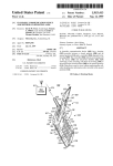
4. Hardware Installation
When installing the EDAC SMS 300, considerations can be broken up into five main categories, Power, Inputs,
Outputs, Aerial installation and other. The sections below will detail the most important issues in each of these
categories.
4.1. Power Supply
The EDAC SMS 300 has a universal input power supply. The unit can accept AC or DC input power between 12
and 28 volts.
The EDAC SMS 300’s idle current draw is quite low, however because of the nature of cellular radio
communications, peak current draw can be quite high, the average current draw also varies depending on the
input voltage. Table 4.1 details the EDAC SMS 300’s approximate current draw figures, when the unit is in
different states.
All figures listed below are based on a supply voltage of +12VDC and an RSSI reading of 25 (very good signal).
These figures will vary depending on supply voltage and cellular signal strength.
State
Approx current draw (mA)
Idle (no outputs active)
30-40 mA
Idle (all outputs active)
90-100 mA
Initialisation
60-100 mA
Sending
80-120 mA
Receiving
60-100 mA
Max
1000 mA
Table 4.1 EDAC SMS 300 Current Draw
4.1.1. DC Power input
The DC power supply input will accept voltage between 12 and 28V, and has reverse polarity protection. The
unit will not power, but will not be damaged if reverse DC voltage, within supply specifications, is applied. The
product is DC over current protected by an internal 1 Amp fuse.
Only replace the fuse with one of the same rated value. Failure to do so may result in
irreversible damage to the product or fire.
4.1.2. AC Power Input
The AC supply input will accept voltage between 12 and 28V.
If an AC Power supply is used it MUST be fully isolated (floating). Use of a non-isolated AC
power supply may result in severe damage to the unit. If there is any doubt about the type
of AC power supply you intend to use, please contact your supplier for more information.
It is required for warranty purposes that external fusing is fitted to the SMS 300 when powered from AC supplies.
This prevents damage from ground loops and surges. Below Fig 4.1.2 details how the external fusing should be
connected.
www.edacelectronics.com
© 2005-2007 EDAC Electronics Ltd
EDAC SMS 300 User Manual
Page 11 of 47
Two 1A Fuses.
One connected
on each AC
supply input
AC~ AC~
AC Power
Supply
Fig.4.1.2 Fitting external fuses to AC powered device
4.2. Inputs
The EDAC SMS 300 has eight fully configurable inputs, capable of accepting three different types of input
signals, Digital (N.O. or N.C.), 4-20mA analog and 0-5V analog. The following sections detail common
configurations for these types of inputs.
4.2.1. Jumper Configuration
The unit has a series of ‘hardware jumpers’ which configure the internal sensing circuitry for the type of input
being used. The jumper for each input must be set correctly for the input to operate properly. A jumper consists
of a group of metal pins, protruding vertically from the circuit board; and a piece of plastic coated metal that
shorts one or more of these pins together.
By default all jumpers are set to ‘digital’. The following process need only be performed if
the setting needs to be changed, or to check the configuration of a particular input.
To configure the jumpers first of all the case end plate and lid need to be removed. Remove the two input
terminal blocks from the unit as shown in Fig. 4.2.1a.
Fig. 4.2.1a Removing the input terminal blocks
www.edacelectronics.com
© 2005-2007 EDAC Electronics Ltd
EDAC SMS 300 User Manual
Page 12 of 47
Next remove the two screws securing the end plate as shown in Fig. 4.2.1b. Carefully move the end plate aside.
Fig 4.2.1b Removing end plate screws
The end plate will still be attached to the circuit board by the aerial cable, be careful not to
stress or break the aerial cable.
Slide the lid out from the extrusion and place to one side as shown in Fig 4.2.1c. The circuit board and
configuration jumpers should now be exposed.
Fig. 4.2.1c Removing the case lid
Extreme caution should be taken not to touch any of the internal components of the SMS
300. Touching the components may cause a static discharge which could severely
damage the unit and void the warranty.
Fig 4.2.1d below details the jumper configuration setup. Note that there is one jumper for each input channel and
that there are two possible configurations: ‘down’ for 4-20mA and ‘up’ for digital or 0-5V.
Also note that input 1 has a ‘Power Supply Monitor’ jumper. Ensure this is set to ‘OFF’ if power supply monitoring
is not to be used. See section 7.6 for more information on Power Supply Monitoring.
www.edacelectronics.com
© 2005-2007 EDAC Electronics Ltd
EDAC SMS 300 User Manual
Page 13 of 47
Fig 4.2.1d Input Jumper Configuration
4.2.2. Digital Configuration
The EDAC SMS 300 requires a ‘clean contact, voltage free’ type digital input. Basically what this means is that
the input needs to be shorted to ground (for N.O.), or disconnected from ground (for N.C.) to indicate an alarm
condition.
When configured as digital the input has an internal pull-up. This means that when the input is not connected to
anything (or floating) it sits at +5VDC. When the input is shorted to ground a small amount of current (around 10
micro amps) is allowed to flow, which pulls the input voltage down to 0VDC. The microprocessor in the EDAC
SMS 300 constantly monitors the voltage on the inputs checking if the input is shorted to ground or not.
No external voltage should be presented to the input terminals of the SMS 300 when
configured as digital. If the device to be monitored has voltage driven outputs, use a relay
to interface them.
Normally the inputs are driven from a relay, micro switch, reed switch or contact output from another control
product (i.e. PLC or data logger). Fig 4.2.2 shows a typical wiring schematic.
+
Power
Supply
Micro-switch,
reedswitch or clean contact
interface
Voltage driven output
from external device
interfaced with relay.
Fig 4.2.2 Typical Digital Wiring
Note that if an AC power supply is being used the GND terminals on the input side must
be used for input signals, NOT the supply ground.
www.edacelectronics.com
© 2005-2007 EDAC Electronics Ltd
EDAC SMS 300 User Manual
Page 14 of 47
4.2.3. 4-20mA Analog Configuration
Generally speaking there are two different types of 4-20mA sensors that are commonly used in industry. ‘Loop
powered’ and ‘Sensor powered’
Loop powered transmitters are often referred to as ‘parasitic powered’ sensors as the sensor transmitter draws
its power from the signal current loop. Fig. 4.2.3a shows a typical wiring diagram for a loop powered transmitter.
+
Power
Supply
Sensor or Transducer
(i.e.
RTD
Temp,
Pressure or Humidity
Sensor).
4-20mA Loop Powered
Transmitter
Loop Loop +
Fig. 4.2.3a Typical 4-20mA Loop Wiring
Note that the power supply used should match the supply requirements of the loop powered transmitter. Loop
powered transmitters should generally only be used by D.C. power supplies. Also note that the ‘INP 1’ terminal is
internally connected to DC- which completes the loop circuit.
Sensor powered or four wire transmitters draw their power from an external power source. Fig. 4.2.3b shows a
typical wiring diagram.
+
Power
Supply
Sensor or Transducer
(i.e.
RTD
Temp,
Pressure or Humidity
Sensor).
+
Loop Loop +
GND
PWR
Power
Supply
4-20mA Sensor Powered
Transmitter
Fig 4.2.3b Typical 4-20mA Sensor Wiring
Note again that the power supply used should match the requirements of the sensor transmitter. Also note that
the ‘INP’ terminals are internally connected to DC – which completes the loop circuit.
www.edacelectronics.com
© 2005-2007 EDAC Electronics Ltd
EDAC SMS 300 User Manual
Page 15 of 47
4.2.4. 0-5V Analog Configuration
0-5V sensors are probably the least commonly used of the three types or sensors. This is due to the fact that
large amounts of the signal voltage can be dropped across long cable runs. A typical wiring schematic is shown
in Fig 4.2.4.
+
Power
Supply
0-5V Sensor
Transmitter
Sensor or Transducer
(i.e. RTD Temp, Pressure or
Humidity Sensor).
GND
Signal
PWR
Fig 4.2.4 Typical 0-5V Wiring
Note that the power supply should match the requirements of the transmitter. One 0-5V transmitter can also
provide signal to multiple devices, such as PLC, display units at the same time.
4.3. Outputs
The outputs on the EDAC SMS 300 are of a relay type, meaning that they can switch small to medium voltages
and currents (Below 50V and 2A AC or DC). Where higher power is required the relays can be used to drive
larger relays.
Below are typical wiring diagrams for both ‘direct load switching’ (Fig. 4.3.1) and ‘relay switching’ (Fig. 4.3.2)
applications.
4.3.1. Direct Load Switching
Output Load. i.e. electric
motor, DC lighting, strobe
light or siren (below 50V
2A).
+
Power
Supply
Fig 4.3.1 Direct Load Switching
www.edacelectronics.com
© 2005-2007 EDAC Electronics Ltd
EDAC SMS 300 User Manual
Page 16 of 47
Note that the load can be powered from the same power supply as the SMS 300, however the supply will need
to match the voltage requirements of the load and will need to be able to supply enough current to power both
the SMS 300 and the load. An additional external power supply can be used for the output load if required.
4.3.2. Relay Switching
Relay
AC~ AC~
Power Supply
+
Power
Supply
Fig 4.3.2 Relay Switching
Note the use of an external power supply, also the coil of the relay must be matched to the voltage of the SMS
300 power supply and the relay contacts must be matched to the voltage and current of the output load.
4.4. Aerial Installation
Aerial selection and installation needs to be carefully considered prior to commissioning. Selection and
positioning of the aerial can make the difference between a system that works well and one that performs poorly.
The EDAC SMS 300 has an SMA Female type aerial connector, allowing a wide variety of aerials to be fitted.
4.4.1. Aerial Selection
Not all aerials are created equal! Many different types of aerials are available on the market and each has its
own pro’s and con’s. EDAC generally recommends and supplies the ‘Pacific Aerials’ range of cellular aerials
because of their durability and performance at a budget price. Below the main type of aerials and the pro’s and
con’s of each are listed.
• Stubby
The stubby aerial is a short ‘spike’ type aerial suitable for use in indoor installations in metropolitan
areas where good signal strength is available, or where mounting of an external aerial is not possible.
This aerial is mounted directly on the SMA connector of the unit. The stubby provides around 1-2dbi
of gain (depending on the type). A stubby aerial is not suitable where the unit is mounted inside a fully
enclosed metal or concrete structure.
• 1/2 Wave
Half wave aerials are a short screw base aerial that can be mounted on external horizontal or vertical
surfaces with the aid of a bracket. These aerial offer around 3-4dbi of gain, and are suited to
metropolitan areas or sites where good general cell coverage is available. Because of the high dome
shaped reception pattern of the ½ Wave it is quite well suited to hilly or obstructed areas also. The ½
Wave is an omni-directional aerial and will connect to the nearest available cell tower
• Elevated Feed Colinear
The colinear is a larger screw base aerial at around 1m in height. The 1/4, 1/8, 1/4 element pattern
provides around 6.5dbi of gain. The elevated feed aids in clearing obstructions when mounting.
Because of the long flat reception pattern of the colinear it is suited to flat sites where the cell tower
may be quite some distance away. The colinear is an omni-directional aerial and will connect to the
www.edacelectronics.com
© 2005-2007 EDAC Electronics Ltd
EDAC SMS 300 User Manual
Page 17 of 47
nearest available cell tower and can be mounted on horizontal or vertical surfaces with the aid of a
bracket
• Yagi
The Yagi is a specialised aerial consisting of a number of receiving elements mounted on a horizontal
feed, much like a UHF TV aerial. The yagi can provide up to 22dbi of gain. The yagi is mounted on a
‘hockey stick’ pole affixed to an external structure. The Yagi provides excellent gain for the most
remote of sites HOWEVER it has an Achilles heel. The Yagi is a directional aerial, this has two major
implications. The first is that when the aerial is mounted, the location of the nearest cell tower needs
to be known and the aerial needs to be pointed directly at it for best performance. The second is that
because it is directional it can only communicate with the cell tower it is pointed at. If this cell tower is
at maximum capacity, or is non-operational when the device is trying to communicate, it is unable to
roam and find another available cell tower due to the directional nature of the aerial. The Yagi is best
suited to the most remote sites or where only one cell tower is within range and the signal strength is
weak.
It is highly recommended that a site survey is undertaken by the installer before the aerial is selected and
installed. Using a test SMS 300 and a selection of aerials and a laptop running ‘SMS 300 Configuration
Manager’ the installer can determine which type of aerial will give best performance. The ‘SMS 300
Configuration Manager’ and its diagnostics interface can be used to obtain an ‘RSSI’ (Relative Signal Strength
Indication) reading. This reading works on a scale of 0 to 31 (zero being no signal, 31 being perfect). A minimum
reading of 10 is recommended for reliable operation.
4.4.2. Mounting
Aerials need to be mounted in the highest possible position, clear of any obstructions, and preferably outside, on
the exterior of a structure. If any aerial is mounted inside a steel shed for example, performance will be severely
affected as the steel structure acts like a shield, blocking signal to and from the aerial. It is advisable to try the
aerial in several different positions, obtaining an RSSI reading from the unit each time.
4.4.3. Cable Length
Cable length can play a critical part in the performance of an aerial. Basically the coaxial cable that connects the
aerial to the device will ‘drop’ a portion of the signal that is transmitted. The longer the cable, the more signal will
be ‘dropped’. This is why keeping the cable as short as possible is important. RG58-AU coaxial will drop up to 35
percent of the signal across a 5 meter run at the common cellular frequencies. Generally we recommend using a
cable that is 5m or less in length. This of course is not always practical as many aerials come pre-fitted with a
length of cable. If there is spare cable left it is important to make sure this is not coiled or looped in any way, try
to avoid the cable crossing over itself or any high voltage or signal cables wherever possible. This will help
minimise cross-talk and interference and will maximise the performance of the aerial.
4.5. Other
4.5.1. RS-232
The EDAC SMS 300 has one fully configurable RS-232 (serial) interface which is used for configuration of the
unit as well as remote communications to external devices (such as a PLC or data logger). The RS-232 interface
is provided via a standard DB9 connector (see section 5 for detailed instructions on using the ‘EDAC 300 Series
Configuration Manager’).
The RS-232 interface is fully configurable with speeds between 1200 and 19200 bps, 7 or 8 data bits, none, odd
or even parity, and one or no stop bits. This allows flexibility in the types of external devices the SMS 300 can
connect to (see section 7.7 for instructions on changing serial port properties).
www.edacelectronics.com
© 2005-2007 EDAC Electronics Ltd
EDAC SMS 300 User Manual
Page 18 of 47
5. Configuration – EDAC 300 Series Configuration Manager
The EDAC SMS 300 is configured using ‘EDAC 300 Series Configuration Manager’, a software interface custom
designed for the EDAC 300 series family of products. This software runs on a Windows based P.C. and
connects to the SMS 300 an RS-232 (Serial) connection. The ‘Configuration Manager’ is used to configure all
aspects of the unit’s functionality. ‘EDAC 300 Series Configuration Manager’ supports Windows © 98, 98SE,
2000 and XP Home SP2 and XP Pro SP2 operating systems.
The ‘EDAC 300 Series Configuration Manager’ provides the option of loading and saving configurations to file,
as well as uploading and downloading configurations to and from a unit. A diagnostics interface is provided
which reports the current status of all aspects of the unit. This includes input and outputs status as well as
network connection status.
The ‘EDAC 300 Series Configuration Manager’ also supports remote configuration and diagnostics for EDAC
300 series products via a dial up CSD connection. A Windows dial-up modem must be properly installed on the
host P.C. to support this function.
5.1. Software Installation
To begin the installation process, execute the installation file located in the ‘Configuration Manager’ folder on the
CD-ROM supplied with the product. The window in Fig. 5.1a should appear.
Fig 5.1a Software Installation - Starting
Click on the ‘Next’ button to proceed. The window shown below in Fig 5.1b will then appear.
Fig. 5.1b Software Installation – Change Settings
On this window the destination directory for installation can be changed if desired. It is recommended that the
default setting is used. Click ‘Next’ to proceed. The window in Fig 5.1c will then appear.
www.edacelectronics.com
© 2005-2007 EDAC Electronics Ltd
EDAC SMS 300 User Manual
Page 19 of 47
Fig 5.1c Software Installation – Check Settings
In this window the installation setting can be reviewed. Click ‘Back’ to go back and change any of these settings,
click ‘Next’ to proceed. The software will now install. The following window will appear when installation is
complete.
Fig. 5.1d Software Installation - Finish
Click on the ‘Finish’ button and the application will launch.
www.edacelectronics.com
© 2005-2007 EDAC Electronics Ltd
EDAC SMS 300 User Manual
Page 20 of 47
5.2. Setup
Before being used the ‘EDAC 300 Series Configuration Manager’ software must be configured correctly for the
type of product being used, and the method being used to connect to the unit.
5.2.1. Product Type
Launch the ‘EDAC 300 Series Configuration Manager’ software either from the shortcut on the desktop or from
the ‘Start’ menu.
From the ‘Settings’ menu select the ‘Product Type’ option as shown in Fig 5.2.1a below.
Fig 5.2.1a 300 Series Configuration Manager
This will then bring up the following ‘Product Selection Form’ window, from here select the ‘300 v3’ product type
(or the appropriate type for the product you wish to configure, this software will configure all types and versions
of the EDAC 300 Series family) and click on ‘O.K.’ to save changes and close the window.
Fig 5.2.1b Product Selection Form
5.2.2. Connection Settings
The ‘EDAC 300 Series Configuration Manager’ must be configured for the type of connection it is going to use as
the method of communication to the EDAC SMS 300 product.
Note that the ‘EDAC 300 Series Configuration Manager’ software can connect using either a local RS-232 serial
port or remotely via a dial up CSD (or Circuit Switched Data) connection (see section 3.1.3 or more information
on requirements for CSD data.
Also note that for CSD connections, a properly installed Windows dial-up modem, connected to a working PSTN
telephone line is also required on the P.C. system where the ‘EDAC 300 Series Configuration Manager’ software
is installed.
Select the ‘Settings -> COM Settings’ menu from the top of the main window a shown in Fig 5.2.2a or use the
keyboard shortcut ‘CTRL+T’.
www.edacelectronics.com
© 2005-2007 EDAC Electronics Ltd
EDAC SMS 300 User Manual
Page 21 of 47
Fig 5.2.2a EDAC 300 Series Configuration Manager
The window in Fig. 5.2.2b will appear.
Fig 5.2.2b Connection Settings – COM Port
Select the COM port, or the Windows dial-up modem to be used to connect to the EDAC SMS 300.
If a COM port is selected choose the baud rate for the connection from the ‘Baud Rate’ list. Note that by default
the RS-232 COM port on the EDAC SMS 300 is set to work at ‘9600’. This setting should not be changed unless
the COM port on the EDAC SMS 300 has been configured to work at a different speed (see section 7.7 for more
information on changing the RS-232 COM port properties)
If a Windows dial-up modem is selected as shown in Fig 5.2.2c, enter the CSD number (see section 3.1.3 for
more information on CSD data numbers) of the remote unit that is to be configured, in the phone number field.
Fig 5.2.2c Connection Settings - Modem
www.edacelectronics.com
© 2005-2007 EDAC Electronics Ltd
EDAC SMS 300 User Manual
Page 22 of 47
5.3. Main Features
The 5 main features of the ‘EDAC 300 Series Configuration Manager’ software can be accessed from five
buttons along the top of the main window. These buttons from left to right, perform the following functions,
Upload Configuration, Download, Load from File, Save to File and Diagnostics.
Fig 5.3 Main Config window
• Upload
Fetches the configuration from the unit and loads it into the ‘Configuration Manager’. If the ‘EDAC 300
Series Configuration Manager’ is setup to use a RS-232 COM connection, configuration retrieval will
start immediately, if it is set up to use a Windows dial-up modem then the modem will dial an connect
before retrieval will begin. A confirmation box will be displayed when retrieval is completed (see
section 5.2.2 for more information on connection types and settings).
• Download
Loads the configuration currently in the ‘EDAC 300 Series Configuration Manager’ software into the
unit. If the ‘EDAC 300 Series Configuration Manager’ is setup to use a RS-232 COM connection,
configuration will start immediately, if it is set up to use a Windows dial-up modem then the modem
will dial an connect before configuration will begin. A confirmation box will be displayed when
configuration is completed (see section 5.2.2 for more information on connection types and settings).
• Load from File
Loads a configuration from a previously saved *.300 file into the ‘Configuration Manager’ a dialog will
open asking for the location of the file to be loaded.
• Save from File
Saves the configuration currently displayed in the ‘Configuration Manager’ to a *.300 file. A dialog will
open prompting for the file save location.
• Diagnostics
Switches to the diagnostics page and starts diagnostics running.
www.edacelectronics.com
© 2005-2007 EDAC Electronics Ltd
EDAC SMS 300 User Manual
Page 23 of 47
5.4. Global/Phone Numbers
The ‘Global’ and ‘Phone Number’ settings relate to all I/O on the unit, these settings are all found on the ‘Unit’
tree of the ‘Configuration Manager ‘as pictured in Fig. 5.4 below.
Fig. 5.4 Global/Phone Numbers Config
• Site Name
The ‘Site Name’ is the text which is included at the beginning of every outgoing message from the
SMS 300. This normally identifies the location or the owner of the unit.
• Allow Public Queries
This option allows the unit to reply to queries from any cellphone. If this option is not selected the unit
will only reply to phone numbers that are programmed in the contact list. If this option is selected it
will reply to queries from all phones (see section 6.3 and section 6.4.1 for more information on
sending queries).
• Unit PIN
The unit PIN defines the PIN that is used when switching outputs. If a PIN is defined then it must be
included at the beginning of all output switching messages.
• Primary Phone Number
The Primary Phone Number is the user that will receive system and forwarded network notification
messages. Enter the cellphone number of the primary user at the top of the list.
• Other Phone Numbers
The other phone number fields are where the cellphone numbers of other users are entered. Note
that these phone numbers can also be other EDAC SMS 300 devices when using the remote output
switching features (see section 7.5 for more information on configuring remote output switching).
• Phone Number Initials
This field allows three initials to be assigned to each contact. These initials are used on other pages
of the ‘Configuration Manager’ and can help identify the contact on pages where the actual number is
not shown (such as the ‘Alarm A’ page)
• Advanced Features
Selecting this box enables automatic output switching options. If remote output switching is required,
this box must be selected (see section 7.4 and section 7.5 for more information on configuring
automatic output switching).
• Auto Report At:
Selecting this box enables the ‘Auto Reporting’ feature. This enables the unit to send an ‘Auto Report’
message at pre-defined intervals, see section 7.1 for more information on ‘Auto Reporting’.
www.edacelectronics.com
© 2005-2007 EDAC Electronics Ltd
EDAC SMS 300 User Manual
Page 24 of 47
5.4.1. Contact Number Format
Note that some networks may require cellular numbers to be programmed in either international or local format
in order for an outgoing SMS to be successfully sent. Vodafone New Zealand for example requires that all
overseas numbers be programmed in international format (i.e. ‘+6421123456’ rather than ‘021123456’). Check
with your network provider for more information on correct number format.
Please carefully check and test all programmed cellphone numbers before
commissioning!
5.5. Inputs
The input configuration relates to input specific settings, such as alarm messages, input configuration and
contact notifications. The settings for each input are found on the ‘Input 1, 2, 3…etc’ trees as pictured below.
Each input tree branch has three tabs for configuring the input, one for general options, one for the first set of
alarm points, and another for the second set of alarm points.
5.5.1. ‘Overall’ Tab
A screen shot of the input tab is shown in Fig. 5.5.1 below. Each option on the tab is explained below this.
Fig. 5.5.1 Input Config
• Input Enabled
Tick this box to enable the input. All other options will be greyed out and unavailable until this box is
ticked.
• Input Type
Select the type of sensor to be connected to this input, digital, 0-5V or 4-20mA.
• Measurement Unit (0-5V and 4-20mA Analog only)
Enter the engineering units (or the measured units) of the sensor connected to this input (i.e. V for
volts, *C for temperature or %RH for humidity). The contents of this field will be suffixed to the
reading from the sensor when its value is sent to a user e.g. Temp Alarm 2.3*C.
• Upper Sensor Limit (0-5V and 4-20mA Analog only)
Enter the upper sensor unit limit in this field, or the actual measured value at 20mA or 5V.
• Lower Sensor Limit (0-5V and 4-20mA Analog only)
Enter the lower sensor unit limit in this field, or the actual measured value at 4mA or 0V.
www.edacelectronics.com
© 2005-2007 EDAC Electronics Ltd
EDAC SMS 300 User Manual
Page 25 of 47
5.5.2. ‘Alarm A’ Tab
Fig. 5.5.2 Alarm A
• Alarm Message
This is the message that will be sent to the users when this input goes into an ‘Alarm State’. If an
analog sensor is being used, the actual scaled reading and the measurement unit will be appended to
this message. (40 chars max)
• Reset Message
This is the message that will be sent to the users when this input goes into a ‘Reset State’. If an
analog sensor is being used, the actual scaled reading and the measurement unit will be appended to
this message. (40 chars max)
• Alarm Condition
Select the physical state of this input that indicates an alarm condition. If this input is configured as
digital, ‘Alarm Off’, ‘Alarm when open’ and ‘Alarm when closed’ options will be available. If a 0-5V or
4-20mA analog is configured, ‘Alarm Off’, ‘Alarm Above’ and ‘Alarm Below’ options will be available.
‘Alarm Off’ means the input will never generate alarm messages. The input will function in a
reporting scenario and its readings will only be transmitted when the unit is queried.
‘Alarm when Open’ (digital only) means the input will be in alarm state when the digital contact
is open and in reset state when the digital contact is closed.
‘Alarm when Closed’ (digital only) means the input will be in alarm state when the digital
contact is closed and in reset state when the digital contact is open.
‘Alarm Above’ (analog only) means the input will be in alarm state when the reading is above
the set point, and will be in reset state when the reading is below the reset point.
‘Alarm Below’ (analog only) means the input will be in alarm state when the reading is below
the set point and will be reset when the reading is above the reset point.
• Alarm on Startup
The SMS 300 records the current state of all configured inputs. If this option is selected on power up
the SMS 300 unit will compare the current state of the input with the last know state, and will send the
appropriate message if it has changed. If this option is not selected the SMS 300 will send notification
messages for all alarm conditions on power-up.
• Alarm Level (0-5V and 4-20mA Analog only)
Enter the real world value where the input will go into ‘Alarm state’.
• Reset Level (0-5V and 4-20mA Analog only)
Enter the real world value where the input will go into ‘Reset state’.
www.edacelectronics.com
© 2005-2007 EDAC Electronics Ltd
EDAC SMS 300 User Manual
Page 26 of 47
• Delay before Alarm/Reset
This option allows a time to be programmed, that the alarm/reset condition must be present for,
before notifications messages will be sent. If the alarm/reset condition is removed before this time
elapses, no notification messages will be sent. This allows for a de-bounce time to be programmed,
which may help to eliminate false alarms. Enter the value in this field in seconds.
• Phone List
Select the appropriate boxes for the users that are to receive alarm and reset messages for this input.
Note that any combination of alarm and reset messages can be assigned to any user. The ‘Alarm’
and ‘Reset’ boxes should be used where the contact is a user, and the ‘Remote Output (Alarm)’ and
‘Remote Output (Reset)’ boxes should be used where the contact is another EDAC SMS 300 unit
(see section 7.4 and section 7.5 for more information on ‘Remote Output Switching’).
• On Alarm Condition
This feature gives the option of automatically switching outputs when this input goes into alarm
condition. From the first drop down box select the output that is to be switched when this input goes
into alarm condition. From the second box select whether the output is to be switched ‘On’ or ‘Off’
when this input goes into alarm condition.
• Switch Local Output on Alarm
Select this check box if you wish to switch an output on this unit when this input goes into alarm state.
If the output you wish to switch is on a second, remote unit, then the phone number of the remote unit
needs to be entered into the contact list and the appropriate ‘Remote Output’ contact notification
boxes need to be ticked (see section 7.4 and section 7.5 for more information on ‘Remote Output
Switching’).
• On Reset Condition
This feature gives the option of automatically switching outputs when this input goes into reset
condition. From the first drop down box select the output that is to be switched when this input goes
into reset condition. From the second box select whether the output is to be switched ‘On’ or ‘Off’
when this input goes into reset condition.
• Switch Local Output on Reset
Select this check box if the output you wish to switch, when this input goes into reset state, is local (or
is on same unit). If the output you wish to switch is on a second, remote unit, then the phone number
of the remote unit needs to be entered into the contact list and the appropriate ‘Remote Output’
contact notification boxes need to be ticked.
5.5.3. ‘Alarm B’ Tab (0-5V and 4-20mA analog only)
The ‘Alarm B’ tab contains an identical set of fields to the ‘Alarm A’ tab. The ‘Alarm B’ tab can be used to set up
a second set of messages, user notifications and alarm/reset points on the one input channel. This allows for a
‘minor alarm’ and ‘major alarm’ scenario to be configured.
www.edacelectronics.com
© 2005-2007 EDAC Electronics Ltd
EDAC SMS 300 User Manual
Page 27 of 47
5.6. Outputs
The settings for each output are found on the ‘Output 1, 2, 3, and 4’ trees as pictured in Fig 5.6 below.
Fig. 5.6 Output Config
• Enabled
Tick this box to enable the output. All other options will be greyed out and unavailable until this box is
ticked.
• Output Name
Enter a name for this output in this box. This name is used in the configuration interface, but can also
be used in the switching message for this output (see section 6.2 for more information on controlling
outputs).
For example:
If output name is
Then output switch command
“Pump”
“PIN# Pump on”
Each name must be unique and cannot be the same as another output on the same unit.
• Default State
This assigns what state the output will be in when the unit is powered up, whether it be due to the unit
suffering power loss, or if it is the first power up.
• Turning On Message
This is the message which is sent to the users when the output is turned on. (40 chars max).
• Turning Off Message
This is the message which is sent to the users when the output is turned off. (40 chars max).
• Phone List
Select the appropriate boxes for the users that are to receive ‘On’ and ‘Off’ messages for this output.
Note that any combination of ‘On’ and ‘Off’ messages can be assigned to any user.
• Self Reset After ‘x’ Seconds
This option enables the output to be configured as self resetting or ‘momentary’ meaning that when
activated, the output self resets after the time period defined in this option. See section 7.2 for more
information on using ‘Self Resetting Outputs’.
www.edacelectronics.com
© 2005-2007 EDAC Electronics Ltd
EDAC SMS 300 User Manual
Page 28 of 47
5.7. Diagnostics Interface
The diagnostics interface (Fig. 5.7) allows the installer/user to see the current status of the inputs, outputs and
network connection in real time. This is useful when installing and mounting aerials, sensors and relays. To start
the diagnostics interface running click on the ‘Diagnostics’ Button at the top of the main window.
If the ‘EDAC 300 Series Configuration Manager’ is setup to use a RS-232 COM connection, diagnostics will start
immediately, if it is set up to use a Windows dial-up modem then the modem will dial an connect before
diagnostics will begin.
Fig. 5.7 Diagnostic Interface
• Input
This reports the current status of each input and the associated message.
• Signal Strength
This field reports the current RSSI (Relative Signal Strength Indication) form the modem. The bar
gives a visual indication, move the cursor over the bar for an actual reading. RSSI is on a scale of 0
to 31, 0 being no signal and 31 being perfect.
• Bit Error Rate
This reports the ‘Bit Error Rate’ of the cellular connection as reported by the modem. This is an
indication of the quality of the cellphone network signal. Bite Error Rate (or BER) is basically a
reading of how much of the digital data that is sent and received is being corrupted. Factors such as
noise signal bounce and incorrect aerial installation can affect BER. Ideally a BER reading of zero
should be seen.
• Cellular Connection
This indicates if a valid connection to the network has been established. If a valid connection is
indicated this confirms the account is properly configured and the unit has everything it needs in order
to operate. If the cellular connection fails, then a button will appear that will allow the user to force the
unit to try to re-connect to the network.
• Output 1, 2, 3, 4
This provides information on the current status of all outputs. Each individual output can also be
switched using the ‘On’ and ‘Off’ buttons next to each output. This can be useful when installing and
testing output wiring.
• Start Diagnostics
This button will start the diagnostics running.
• Stop Diagnostics
This button will stop the diagnostics running. The last known values for each field will be displayed,
until either the page is changed or the diagnostics is started again.
www.edacelectronics.com
© 2005-2007 EDAC Electronics Ltd
EDAC SMS 300 User Manual
Page 29 of 47
6. SMS 300 - Notification, Control and Queries
The main method of communication the EDAC SMS 300 uses is SMS (text) messaging. The unit can send
messages to, and receive messages from standard cellular phones and other SMS 300 units. This can provide
information about the current state of inputs and outputs, be used to switch outputs on and off and provided
information about the system and cellular connection.
For information about sending and receiving SMS on your mobile phone see your phones user manual or
contact your cellular service provider.
6.1. Alarm Notification Messages
Alarm notification messages are generated when an input changes state or an alarm condition is detected.
These messages are user configurable and can be sent to any combination of cellphone users.
Alarm notification messages are made up of several different messages from within the SMS 300 unit. An
example of a typical alarm message follows.
SMS 300 Demo
Input 1 Alarm
09:11 19/07/05
‘Site Message’
‘I/O Message(s)’
‘Time/Date’
The SMS 300 continually monitors the state of all inputs. Occasionally, if an analog sensor becomes faulty or is
not properly configured, it may read out of bounds. The SMS 300 will notify the primary user (see section 5.4 for
more information on configuring the primary user) of the fact that an input sensor is reading out of bounds. This
message will look similar to the following example:
SMS 300 Demo
Input 1’s sensor is reading out of bounds, it might be faulty.
09:11 19/07/05
If this message is received the sensor, its associated wiring and the configuration should be carefully checked.
6.2. Controlling Outputs
The user can remotely control the state of any output by sending an SMS message to the unit. The EDAC SMS
300 uses two levels of security to ensure only authorised users can switch outputs. These are ‘PIN’ security and
‘Caller ID’ security. This means that the user must have two things in order to a switch an output, they must
know the PIN number of the unit (if a PIN has been programmed) and they must have the number of the phone
they are sending the command from, programmed into the phone number list of the unit.
6.2.1. Switching Commands
The message to switch an output must be in the correct format to be accepted. The format is as follows:
<PIN#>space<Output number>space<on/off>
i.e.
‘1234 1 On’
Note the spaces between the PIN number, the output number and the command. Also note that if no PIN
number has been configured in the unit, the PIN part of the message is not required.
Also note that the <Output number> part can be replaced by the ‘Output name’ (see section 5.6 for details on
configuring output names). For example if output one is setup with the name of ‘Pump’ the command could look
like this:
‘1234 Pump On’
6.2.2. Output Switch Command Expiry Times
Output control commands can often be time sensitive and due to the fact SMS messaging is not a time critical
service, some commands should not be actioned if they are received after a certain time.
The EDAC SMS 300 allows an expiry time and date to be set on output command messages so that if they are
received after a certain pre-defined time and date they are discarded by the EDAC SMS 300.
The context of the message should be structured as follows:
<Output Control Command>;<Expiry Time/Date Command>
www.edacelectronics.com
© 2005-2007 EDAC Electronics Ltd
EDAC SMS 300 User Manual
Page 30 of 47
The ‘expiry time/date’ command will only have an effect when coupled to a remote control command. However
system and remote control commands are not dependant on being coupled to an ‘expiry time/date’ command,
and will function independently.
The format of the ‘expiry time/date’ command is as follows:
YYYYMMDDHHMMSS
Where:
YYYY is the calendar year of expiry
MM is the calendar month of expiry
DD is the calendar day of expiry
HH is the hour of expiry (in 24 hour format)
MM is the minutes of expiry
SS is the seconds of expiry
For example:
Pump 4 Off;20070719000100
This command would be actioned if received before 00 hours 01minutes 00 seconds (or 12:01am) on the 19th of
July 2007
Note that the resolution with which expiry time is defined can be set by omitting parts of the command. For
example, a resolution of one hour can be set on a message by not defining the seconds and minutes in the
command. The omitted parts are assumed to set to zero.
For example:
Pump 2 On;2007071913
This will be actioned if received before 1pm on the 19th of July 2007. Note how the minutes and seconds are not
defined.
Resolution can be defined up to one year, so a message could be defined as valid for a whole year
For example:
Pump 2 On;2008
This will be actioned if received before the end of 2007. Note how the seconds, minutes, hours, days and month,
are not defined.
6.2.3. Responses
The EDAC SMS 300 can be configured to respond to output commands, confirming that the command message
has been received and the action has been taken (see section 5.6 for more information on configuring output
switching notification). Output response messages are generated whenever an output is switched (either
remotely or locally).
A typical response to an output command will look like the following:
SMS 300 Demo
Output 1 On
09:11 19/07/05
‘Site Message’
‘Output Message’
‘Time and Date’
If an output command has been sent by a valid user (i.e. phone number programmed in contact list) and the
command is invalid or in an incorrect format the SMS 300 unit will respond with the following message.
SMS 300 Demo
The command or pin number was not valid
09:44 22/07/05
If an output command has been sent by a valid user (i.e. phone number programmed in contact list) and the
command is valid but the output is not enabled, the SMS 300 unit will respond with the following message.
SMS 300 Demo
Output ‘x’ is not enabled
09:44 22/07/05
www.edacelectronics.com
© 2005-2007 EDAC Electronics Ltd
EDAC SMS 300 User Manual
Page 31 of 47
If a valid command is sent by a valid user, but the expiry time/date has lapsed and the message is deemed to
have expired, the EDAC SMS 300 will respond with the following message:
SMS 300 Demo
Expired message received:
“<message content>”
09:11 19/07/05
‘Site Message’
‘Time and Date’
If a command is sent by an invalid user (I.e phone number not programmed into contact list), no response will be
sent.
6.2.4. Multiple Output Commands
It is possible to switch multiple outputs with one SMS message. This saves the time and expense of sending
multiple messages when more than one output has to be switched at once. Binary like values are used to
indicate the required state of each output. The format for switching multiple outputs is as follows:
<PIN#>space<outall>space<OUT1><OUT2><OUT3><OUT4>
Replace the <OUTx> field with any of the following values to indicate the required state of the output.
1
0
x
=
=
=
ON
OFF
Make no change to current state
For example a typical multiple output switch message may look like the following:
‘1234 outall 110x’
This message would switch outputs 1 and 2 on, output 3 off and make no change to output 4. Notification
messages will be sent for all outputs that have been switched. The command above would initiate three separate
responses as detailed below (assuming the outputs are configured to send notifications messages – see section
5.6 for more information on configuring output notification messages).
SMS 300 Demo
Output 1 On
09:11 22/07/05
‘Site Message’
‘Output Message’
‘Time and Date’
SMS 300 Demo
Output 2 On
09:11 22/07/05
SMS 300 Demo
Output 3 Off
09:11 22/07/05
6.3. Status Query
The status query provides information about the current state of all inputs and outputs. Note that if the ‘Public
Queries’ option is not enabled, the number of the cellphone has to be programmed into the contact list in order to
receive a response (see section 5.4 for more information on enabling public queries).
To obtain a status report, send the following command:
Status
A typical response to this command might look as follows: Note that this information may be split over two
separate SMS messages if required.
SMS 300 Demo
Input 1 Alarm
Input 2 OK
Input 3 OK
Output 1 On
Output 2 Off
Output 3 Off
09:11 17/07/05
‘Site Message’
‘Input 1 current status’ (alarm message)
‘Input 2 current status’ (reset message)
‘Input 3 current status’ (reset message)
‘Output 1 current status’ (turning on message)
‘Output 2 current status’ (turning off message)
‘Output 3 current status’ (turning off message)
‘Time and Date’
Disabled I/O will not appear in a reply to a status query.
www.edacelectronics.com
© 2005-2007 EDAC Electronics Ltd
EDAC SMS 300 User Manual
Page 32 of 47
6.4. Advanced SMS Commands
Additional SMS commands are available for advanced users as detailed in the following sections.
6.4.1. System Query
The system query provides information about the status of the units’ cellular connection. In order to obtain a
system report, send the following command:
Sys
A typical response to this command will look like the following
SMS 300 Demo
RSSI = 20
BER = 0
09:11 17/07/05
‘Site Message’
‘RSSI reading from modem’
‘BER reading from modem’
‘Time and Date’
RSSI (or ‘Received Signal Strength Indication’) gives information about the strength of the cellular network
signal. RSSI is measured on a scale of 0 (no signal) to 31 (perfect signal). Note that a minimum RSSI reading of
10 is recommended for reliable operation.
BER (or ‘Bit error Rate’) gives an indication of the quality of the received signal. It gives an indication of the level
of errors encountered when transmitting digital data. A BER reading of zero should normally be encountered.
6.4.2. Multiple Commands
Multiple SMS commands can be sent together in one message. This saves the time and expense of sending
multiple messages to perform more than one task. Use the standard commands as described in the sections
above, separated by a ‘+’ symbol.
For example:
sys+status
This command would return both system and status information in separate messages. Note that the
information, from each query, may be split over more than one message if required.
Another example
1234 Output1 On+1234 Output 2 Off
This command would turn output 1 on, and output 2 off at the same time. The responses will be sent back as
required/configured (see section 5.6 for more information on configuring output responses).
www.edacelectronics.com
© 2005-2007 EDAC Electronics Ltd
EDAC SMS 300 User Manual
Page 33 of 47
7. Application Notes / Advanced Features
7.1. Auto Reporting
The ‘Auto Reporting’ feature is designed to give peace of mind in applications where the unit is either very
remote, or is mission critical to the operation of the equipment it is connected to. This feature allows the unit to
automatically send a status message, at a pre-defined interval, on a daily, weekly or monthly basis, providing
peace of mind that the unit is alive and operating correctly.
The ‘Auto Report’ message is sent to the ‘Primary User’ in the phone number list (see section 5.4 for more
information on Configuring the ‘Primary User’).
The auto report feature is configured on the ‘Global/Phone Numbers’ page of the ‘EDAC 300 Series
Configuration Manager’ as described in section 5.4 and as shown below in Fig 7.1.
Fig 7.1 EDAC 300 Series Configuration Manager - Unit Page
Tick the ‘Auto Report At’ check box to enable the feature. Set the time of day for the message to be sent, and
then select either a daily, weekly or monthly interval. If a weekly interval is selected, choose the day of the week
for the ‘Auto Report’ message to be sent, if monthly is selected select the day of the month for the ‘Auto Report’
message to be sent.
th
th
st
Note that if monthly is selected, and either the 29 , 30 or 31 day of the month is selected, in months where
the day selected does not exist (February for example only has 28 days) the message will be sent on the last
day of month that the message is due for delivery in.
An example of what the ‘Auto Report’ message might look like is shown below:
SMS 300 Demo
Reporting:
Input 1 Alarm
Input 2 OK
Input 3 OK
Output 1 On
Output 2 Off
Output 3 Off
09:11 17/07/05
‘Site Message’
‘Reporting Message indication’
‘Input 1 current status’ (alarm message)
‘Input 2 current status’ (reset message)
‘Input 3 current status’ (reset message)
‘Output 1 current status’ (turning on message)
‘Output 2 current status’ (turning off message)
‘Output 3 current status’ (turning off message)
‘Time and Date’
Note that the contents of this message may be split over two or more SMS messages if required
www.edacelectronics.com
© 2005-2007 EDAC Electronics Ltd
EDAC SMS 300 User Manual
Page 34 of 47
7.2. Self Resetting Outputs
The outputs on the EDAC SMS 300 can be configured as self resetting, or ‘momentary’. The Self Resetting
output feature allows the user to configure an output on the SMS 300 to turn on momentarily, for a pre-defined
time when activated, and then automatically turn itself off.
This enables the SMS 300 to simulate a button press for starting and stopping devices such as pump soft start
controllers, centre pivot and lateral irrigators, and process machinery.
The ‘Self Resetting Output’ feature is configured in the output page as described in section 5.6, and as shown
below in Fig 7.2.
Fig 7.2 Output Configuration
To disable the ‘Self Reset’ feature and set the outputs as latching, enter ‘0’ into the ‘Self Reset after x seconds’
field. To enable the feature enter the time (in seconds) that the output will remain active for before self resetting.
Note that this action will only occur when the output is being switched from the ‘Default State’ (as configured in
the output page) and not if the output is manually switched back to the ‘Default State’ before the self reset time
elapses.
7.2.1. Single Word Output Commands
When the ‘Self Resetting Output’ feature is enabled, single word output commands can be used. If the ‘Output
Name’ is a single word, with no spaces, just the text entered in the ‘Output Name’ field can be used to switch the
output from the ‘Default State’, without the ‘On’ or ‘Off’.
For example, using the configuration in Fig 7.2 above (‘Default State’ is “Off”, ‘Output Name’ is “Start” and ‘Self
Reset after x Seconds’ is set to ”6”) sending the SMS message “Start” to the unit will turn the output on for 6
seconds, then it would self reset and turn off.
Note that the command will still have to meet the PIN number and caller ID security requirements described in
section 6.2 and that the ‘Output Name’ used can not contain any spaces.
7.3. Through Mode CSD Data Connection
The RS-232 serial port on the EDAC SMS 300 can be used to connect to external devices such as PLC’s or
data-loggers. Put simply, the SMS 300 works like a RS-232 modem, but rather than working though traditional
fixed line services, it works through wireless cellular networks using a technology called CSD or Circuit Switched
Data. Remote connections can be established through the SMS 300 allowing data communications between a
base P.C. and the remote device.
The cellphone account that the SMS 300 is connected on will need to have CSD enabled. See section 3.1.3 for
more information on Circuit Switched Data numbers.
www.edacelectronics.com
© 2005-2007 EDAC Electronics Ltd
EDAC SMS 300 User Manual
Page 35 of 47
To initiate a through mode connection, the modem on the P.C. must start a connection with the SMS 300 unit, by
dialling the number of the SMS 300 unit. The P.C. modem and the SMS 300 should negotiate a connection.
Once connected data should be able to be sent to and from the SMS 300.
A terminal program such as ‘HyperTerminal’ or ‘Terra Term’ will need to be used to control the P.C. modem.
Connect a terminal program to the COM port the modem is connected to (if the modem is internal the COM can
normally be found in the hardware properties).
Some basic commands should be entered into the P.C. to set it up to work with the SMS 300. Below is an
example of the commands that need to be entered to set up the P.C. modem and initiate the connection.
AT&F
ATn1
AT&k4
<ENTER>
<ENTER>
<ENTER>
‘Factory Reset modem’
‘Enable auto baud rate detection’
‘Turns on flow control’
ATDT<Phone#>
<ENTER>
‘Dials SMS 300 and connects’
Use the phone number of the SMS 300 in the <Phone#> field. The P.C. modem should now dial the SMS 300
and connect. Wait for the following response to confirm the connection was successful.
CONNECT 9600
The P.C. and the SMS 300 are now connected and data can be sent and receive between the two units.
The properties of the SMS 300’s RS-232 port can be configured to work with any device that is externally
connected. See section 7.7 ‘Serial AT Commands’ for more information on changing the properties of the RS232 port. It should be noted that if these are changed the unit may no longer communicate with ‘SMS
Configuration Manager’.
7.4. Automatic Local Output Switching
The SMS 300 can be configured to automatically switch the state of an output depending on the state of an
input. For example an input can monitor a temperature sensor and automatically turn on a fan if it gets to hot.
The following section will explain how to configure the SMS 300 to automatically switch local (i.e. on the same
unit) outputs.
First of all the ‘Advanced Features’ option needs to be enabled. Using the ‘SMS 300 Configuration Manager’
(see section 5 for more info on ‘EDAC 300 Series Configuration Manager’) switch to the unit page and select the
‘Advanced Features’ option as shown in Fig 7.4a below.
Fig 7.4a Enabling Advanced Features
Next the output that needs to be switched must be configured correctly. Bring up the configuration page for the
output that you wish to control. This page is shown below in Fig. 7.4b. Make sure the output is enabled and the
‘Turning On’ and ‘Turning Off’ messages have been set up. The output should also be set up to send notification
messages if required.
www.edacelectronics.com
© 2005-2007 EDAC Electronics Ltd
EDAC SMS 300 User Manual
Page 36 of 47
Fig. 7.4b Output Config
The input that is to control the output then needs to be set up. Bring up the appropriate input configuration page
as shown below in Fig 7.4c.
Fig. 7.4c Switching Config
Next to the ‘On Alarm Condition’ text, are two drop down boxes. Select the output to be switched from the first
box, and the action to be taken when this input alarms from the second box. Next to ‘On Reset Condition’ select
the output to be switched and the action to be taken when the input goes into a reset state. Ensure both ‘Switch
local output on alarm’ and ‘Switch local output on reset’ boxes are ticked.
Also note that the ‘Alarm Condition’ box must not be set to ‘Alarm Off’, (i.e. input must be alarming) in order for
the output to be switched.
The output should now be automatically controlled by the state of the input. Note that the output can still be
switched manually. Also note that If the output is already in the state that it is to be switched to when a particular
event occurs, no change will be made, and no output notification will be sent.
www.edacelectronics.com
© 2005-2007 EDAC Electronics Ltd
EDAC SMS 300 User Manual
Page 37 of 47
7.5. Automatic Remote Output Switching
As well as automatically controlling outputs on the same unit, the SMS 300 can automatically control outputs on
other remote units. Because of the nature of cellular communications the physical distance between the two
units is irrelevant, as long as cellular reception is available to both units. The diagram below graphically shows
how two units can be linked together.
An example application for this feature could comprise of a frost monitoring and irrigation start system. One SMS
300 may be connected to a temperature sensor out in the middle of the orchard, but the pump that needs to be
started when a frost occurs is some distance away at the edge of the orchard.
One SMS 300 can be connected to the pump and one to the temperature sensor. The two units can then
communicate with one another when a frost occurs, the first unit detecting the frost, then sending an SMS to the
second which starts the irrigation, which in turn, then notifies the user of the event.
The setup of this feature is very similar to that of ‘Automatic Local Output Switching’ (see section 7.4); however
there are a few important setting that need to be configured properly.
The first is that the unit PIN needs to be EXACTLY the same on both units. Ensure the ‘Unit PIN’ as shown in Fig
7.5a, is identical on both units.
The phone number of the remote unit needs to be entered into the contact list of the first unit and vice versa.
This is so that the remote unit and the local unit know to accept commands from each other. Ensure the phone
number of the other unit is entered in the contact list in each unit. The example in Fig 7.5a shows the user
configured in contact 1 (with initials ABC) and the remote unit configured in contact 2 (with initials REM).
Fig 7.5a Remote Output Switching Setup
The last thing is to configure the base unit to send the appropriate command to the remote unit. This is setup in a
similar fashion to local output switching, but the ‘Switch Local Output on Alarm’ and ‘Switch local Output on
Reset’ boxes are not ticked, and the ‘Remote Output (Alarm)’ and ‘Remote Output (Reset)’ boxes must be ticked
next to the contact that contains the base units’ number.
The example in Fig 7.5b below shows the user configured on contact 1 (with initials ABC) and the remote unit
configured in contact 2 (with initials REM).
www.edacelectronics.com
© 2005-2007 EDAC Electronics Ltd
EDAC SMS 300 User Manual
Page 38 of 47
Fig 7.5 Remote Output Alarm Setup
Note how the ‘Remote Output (Alarm)’ and ‘Remote Output (Reset)’ tick boxes are used for the remote unit
contact.
7.6. Power Supply Monitoring
The SMS 300 unit has the ability to monitor the voltage supplied to it when running from a D.C. power supply
(contact the manufacturer for more information on monitoring AC supply voltage). The first input is dedicated
when this function is enabled. There are two steps to setting up power supply monitoring, hardware setup and
configuration setup.
7.6.1. Hardware Setup
The ‘Power Supply Monitoring’ Jumper needs to be enabled before this feature can be used. See section 4.2.1
for more information on changing the power supply monitoring jumper.
Please note that changing this jumper disables the standard features of input 1. Any sensors or contacts
connected to input 1 will no longer operate. Shifting the power supply monitoring jumper to ‘ON’ effectively
disconnects the input 1 terminal from the system. Any existing sensors or contacts on input 1 will need to be
shifted to another spare input if power supply monitoring is enabled.
7.6.2. Configuration Setup
The first input is dedicated when the power supply monitoring jumper is changed and as such the configuration
for input 1 needs to be correct for this to function correctly.
Fig. 7.6.2a below shows the values that need to be entered on the ‘Input 1’ configuration page.
Fig. 7.6.2a PSU Monitoring Setup
www.edacelectronics.com
© 2005-2007 EDAC Electronics Ltd
EDAC SMS 300 User Manual
Page 39 of 47
Ensure the input is enabled, ‘Input Type’ is set to ‘0-5V’, ‘Measurement unit’ is entered as ‘V’, ‘Upper sensor limit’
is ’53.75’ and ‘Lower sensor limit’ is -40.25.
Alarm conditions and notification messages can now be set up for the power supply monitoring. Change to the
‘Alarm A’ tab to configure these. Fig. 7.6.2b shows how these might be typically set up.
Fig 7.6.2b PSU Monitoring Alarms
Note that when the actual voltage falls below the value in ‘Alarm Level’, the input will alarm, and when the actual
voltage comes back up above the value in ‘Reset Level’, the input will reset.
www.edacelectronics.com
© 2005-2007 EDAC Electronics Ltd
EDAC SMS 300 User Manual
Page 40 of 47
7.7. Serial AT Commands
Some features of the SMS 300 can be accessed through a terminal program connected to the COM port of your
PC (e.g. Hyper-Terminal). The terminal session should be configured to 9600 baud rate, 8 data bits, no parity
and 1 stop bit (9600 8,n,1).
It should be noted that using these commands is recommended for advanced users only.
Incorrect use of these commands may render the unit inoperable.
To use one of the commands type the command into the terminal window and press enter. The SMS 300 will
respond as required.
Basic Commands
Command
Response
Function
AT+BAUD?
+BAUD : {"1200","2400","4800","9600",
"14400","19200"}
Returns the values the baud rate can be set
to.
AT+BAUD=?
+BAUD=<baud rate>
Returns the current baud rate
AT+BAUD=<baud rate>
OK
Sets the baud rate to the defined value.
Note you must now change the baud rate set
in your terminal application to continue using
this.
Returns ERROR if the functions was not
performed.
ERROR
AT+COMM=?
+COMM = 8,n,1
Returns the current setup of the COM port.
Note this may need to be changed to
interface with external devices, e.g. PLC’s.
AT+COMM?
+COMM :
<data>,<parity>,<stop>
Returns the format to change the COM port
settings.
AT+COMM=<data>,
<parity>,<stop>
OK
Sets the COM port with the new settings.
ERROR
Returns ERROR if the functions was not
performed.
AT+IN<input number>
+IN1=open
Returns the current status of the input
chosen, e.g. AT+IN1 returns the state of
input 1.
AT+OUT<output number>
+OUT1=1
Returns the current state of the output
chosen, e.g. AT+OUT1 returns the state of
output 1.
AT+OUT1=<state>
OK
Turns the output on or off.
AT+OUT1=ON will turn output 1 on.
State = {ON, OFF}
ERROR
Either the output is not enabled or is an
invalid output number.
OK
This allows you to control all of the outputs
with one command. ‘a’ represents output 1,
‘b’ represents output 2, ‘c’ represents output
3,
‘d’
represents
output
4.
E.g.
AT+OUTALL=0110 would turn output’s 1 and
4 off and output’s 2 and 3 on.
ERROR
The command was entered incorrectly.
AT+OUTALL=<abcd>
www.edacelectronics.com
© 2005-2007 EDAC Electronics Ltd
E.g.
EDAC SMS 300 User Manual
Page 41 of 47
AT+RSSI
+RSSI=<RSSI reading>
Returns the current RSSI (Received Signal
Strength Indicator).
If the value 99 is
received, the value is unknown.
AT+BER
+BER=<BER value>
Returns the current BER (Bit Error Rate). If
the value 99 is received, the value is
unknown.
AT+CSQ
+CSQ: <RSSI>, <BER>
Returns both the RSSI and BER values for
the modem
AT+CNI
+CNI=<status>
Returns the current network status. If the
modem is successfully connected to the
network +CNI=OK is returned, otherwise
+CNI=failed is returned.
AT+RN
+CNI=<status>
At+RN forces the modem to try and
reconnect to the network. The SMS 300 will
only attempt this when +CNI=failed. AT+RN
replies with the status of the network
connection once the attempt to reconnect
has been completed.
AT+TIME=?
+TIME=”dd/mm/yy,hh:mm:ss”
Returns the current time set on the SMS
300. This is updated from the P.C. when the
unit is configured.
AT&F
OK
Reset the Config to the factory configuration
AT&R
OK
This gives SMS 300 a software reset. So the
unit starts up again.
AT+SMS=”<phone
number>”, <message>
OK
This is used to send a SMS. The phone
number must be a valid cell phone number,
and the message can’t exceed 160
characters. Note the message will be sent in
capitals.
AT+SVER
+SVER: 1.50
Returns the version of software in the SMS
300
AT+CGMS=
+CMGS=<x>
Sets and returns the level of system
reporting for initialisation.
?
=?
1
0
ATE
‘?’ returns the current status
‘=?’ returns valid values
‘1’ sets full reporting on initialisation
‘0’ turns reporting on initialisation off
OK
Sets the echo setting for the RS-232 port
‘0’ turns echo off
‘1’ turns echo on
0
1
AT+VERBOSE=
0
1
2
OK
Sets the level of reporting on the RS-232
port by manipulating the ‘ATE’ and
‘AT+CMGS’ commands as well as setting the
verbose flag.
‘0’ sets the port to silent mode,
‘1’ sets the port to low reporting (sets
+CGMS to 1 and ATE to 0)
‘2’ sets the port to full reporting (sets
+CGMS to 1 and ATE to 1).
www.edacelectronics.com
© 2005-2007 EDAC Electronics Ltd
EDAC SMS 300 User Manual
Page 42 of 47
Serial Through Mode Commands
###
OK
This command is only accessible when the
SMS 300 has been accessed via a CSD
modem connection (i.e. Remote mode). ###
takes the SMS 300 out of a transparent
serial link, and allows you to access all of the
normal commands.
AT+EXTM
OK
This command is only accessible when the
SMS 300 has been accessed via a CSD
modem connection (i.e. Remote mode).
After you have pushed ### you can use this
command to return to a transparent external
through mode (as when the connection was
first established.)
www.edacelectronics.com
© 2005-2007 EDAC Electronics Ltd
EDAC SMS 300 User Manual
Page 43 of 47
8. Glossary
Inputs
Inputs are devices, sensors or situations that can cause the SMS 300 to go into an alarm state and send
notification messages.
Digital
Digital is a type of input, consisting of connecting an input to ground and disconnecting an input form ground.
N.C. (Normally Closed)
N.C. is a type of digital input, which is in a reset condition when shorted to ground (or closed) and in alarm
condition when disconnected from ground (or open).
N.O. (Normally Open)
N.O. is a type of digital input, which is in a reset condition when disconnected from ground (or open) and in
alarm condition when shorted to ground (or closed).
Analog
Analog is a type of input, consisting or a voltage or current signal over a range of 4-20mA or 0-5V. The analog
signal can be scaled and converted into ‘Real World’ values, meaning the readings come back in the actual units
that are being measured (i.e. temp = *C or pressure = kPa). Alarm and reset points are can be assigned in real
world units. When these points are crossed, notification messages can be sent.
0-5V
0-5V is a type of analog input. It consists of a constant voltage, between 0 and 5 VDC, being presented to the
SMS 300. The unit reads this value and scales it into real world units.
4-20mA
4-20mA is a type of analog input. It consists of a constant current flow, between 4 and 20mA, being presented to
the SMS 300. The SMS 300 reads this value and scales it into real world units.
Loop Powered
Loop powered is a type of 4-20mA analog sensor which draws its power supply form the input terminal of the
SMS 300 (sometimes referred to as parasitic power).
Sensor Powered
Sensor powered is a type of 4-20mA analog sensor which draws its power from an external supply, different
form the supply to the SMS 300.
Alarm
Alarm is a pre-defined condition, detected by an input sensor, which will initiate notification messages.
Reset
Reset is a pre-defined condition, detected by an input sensor, which will initiate notification messages.
CDMA
CDMA (or Code Division Multiple Access) is a cellular communications network scheme, used by Telecom NZ
and Telstra Australia. CDMA allows 3G technologies such as video/picture messaging and high speed data
transfers to occur.
GSM
GSM (or Global System for Mobile communications) is a cellular communications network scheme, used
commonly by Vodafone. GSM is an accessible, highly reliable, standard for voice, picture/video and data
communications.
SIM card
A SIM card (or Subscriber Identity Module) is a small card used on GSM cellphone network. The SIM card
contains information about the account that the phone is connected on, as well as the number of the phone.
SMS
SMS (or Short Message Service) is a text message delivery service on cellular networks. The EDAC SMS 300
uses SMS messaging as it main means of communication.
CSD
CSD (or Circuit Switched Data) is a term for modem communications that occur through cellular networks. The
EDAC SMS 300 uses CSD for transparently communications with externally connected devices.
Phone ESN
The Phone ESN (or Electronic Serial Number) is used to identify CDMA cellular devices. The Phone ESN is
required when connecting a CDMA cellular device on the network. The Phone ESN can be found on a sticker on
the bottom of the SMS 300-CNZ or 300-CAU.
www.edacelectronics.com
© 2005-2007 EDAC Electronics Ltd
EDAC SMS 300 User Manual
Page 44 of 47
Pre-Pay
‘Pre-Pay’ is a way of paying for cellular services. A device connected on a ‘Pre-Pay’ account is ‘topped up’ with
credit, which is used up when services are accessed. ‘Pre-Pay’ is useful for non-critical monitoring and control
applications. Care is advised however when using ‘Pre-Pay’ in critical applications. This is due to the fact that if
the device runs out of credit, NO communications will be allowed by the network.
RSSI
RSSI (or Received Signal Strength Indication) is an indication of the strength of the cellular network signal. RSSI
is read on a scale of 0 (no signal) to 31 (Perfect signal).
BER
BER (or Bit Error Rate) is an indication of the quality of the received signal. BER is calculated from the ratio of
good data packets received compared to the number of bad or corrupted data packets received. Normally a BER
reading of 0 should be seen.
Jumper
A jumper is a connector device used to change the hardware configuration of the inputs on an EDAC SMS 300.
The Jumper consists of three (or more) metal pins protruding from the circuit board at right angles, and a piece
of plastic coated metal which slides over two (or more) of the pins, connecting them together.
Query
A query is a request for information sent to the EDAC SMS 300 unit. Depending on the type of query (see
section 6.3 and section 6.4.1 for more information of the different types of queries) the SMS 300 will reply back
with the requested, relevant information.
RS-232 (Serial)
RS-232 (or serial) is a communications protocol used by computers for sending and receiving information. RS232 is commonly used for configuring devices, such as the SMS 300, from Windows based P.C.s.
www.edacelectronics.com
© 2005-2007 EDAC Electronics Ltd
EDAC SMS 300 User Manual
Page 45 of 47
9. Product Support
For end-user level customer support, contact your local distributor or installer.
www.edacelectronics.com
© 2005-2007 EDAC Electronics Ltd
EDAC SMS 300 User Manual
Page 46 of 47
10. Notes
www.edacelectronics.com
© 2005-2007 EDAC Electronics Ltd
EDAC SMS 300 User Manual
Page 47 of 47
11. Document History
Version
Date
Author
1.0
13/10/2005
Chris Butler
Document Creation
1.1
5/12/2005
Chris Butler
Added ‘External AC Fusing’. Added ‘Approved Networks
List’. Various minor corrections and improvements.
1.2
30/08/2007
Chris Butler
Added major feature ‘Output Command Expiry Times’.
Updated wiring diagram with more accurate representation
of SMS 300. Various minor changes and improvements
Chris Butler
Added major features ‘Self Resetting Outputs’, ‘Auto
Reporting’, ‘Single Word Output Commands’ and ‘Config via
CSD’. Updated Section 5 ‘Configuration – EDAC 300 Series
Configuration Manager’ for new release version. Added
section on CSD Data numbers. Updated ‘Contact number
Format’ section. Hyperlinks and formatting updated. Various
minor improvements and corrections.
1.3
05/11/2007
Notes
www.edacelectronics.com
© 2005-2007 EDAC Electronics Ltd