1
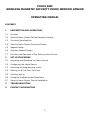
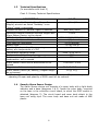
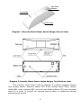
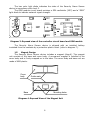
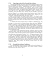
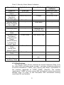
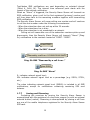
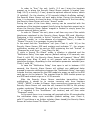
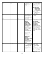
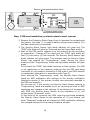
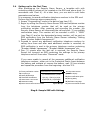
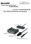
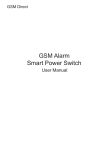
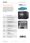
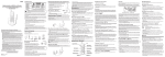
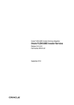
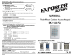
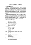
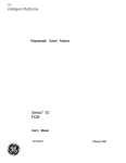
1
POLUS GSM
WIRELESS MAGNETIC SECURITY DOOR\WINDOW SENSOR
OPERATING MANUAL
CONTENTS
1
DESCRIPTION AND OPERATION
1.1
Function
1.2
Security Alarm Sensor Device Package Contents
1.3
Technical Specifications
1.4
Security Alarm Sensor Structural Design
1.5
Magnet Design
1.6
Keychain Magnet Design
1.7
Function and Operation of the Security Alarm Sensor
2
SET-UP PROCEDURE
2.1
Preparing and Operating the Alarm Device
2.2
Configuring the Alarm Device
2.3
Accessing the Programming mode
2.4
Setting-up for the First Time Use
2.5
Verifying set-up
2.6
Changing & Adjusting the Parameters
2.7
Security Alarm Sensor Device Installation
3
TROUBLESHOOTING
4
CONTACT INFORMATION
2
1
DESCRIPTION AND OPERATION
1.1
Function
The POLUS GSM Security Alarm Sensor Device is designed and made
to detect the unauthorized opening of doors, windows and hatches, etc.,
and when triggered, to transmit an SMS alert notification and/or place a
call to the owner’s telephone.
The alarm device supports the following operational modes:
- Programming;
- Disarmed;
- “ArmDelay”;
- Armed “On Guard”;
- Active “AutoArm” Delay;
- Alarm;
- Standby “NotDelay”;
POLUS GSM Security Alarm Sensor Device FEATURES:
- Installs at any location with mobile GSM reception;
- Arms via a key chain magnet and/ or an optional external button/
switch (optional external button/ switch not included in the package);
- Disarms via a mobile telephone during Active “AutoArm” Delay, Alarm
or Standby “NotDelay” modes;
- Automatically re-arms to “On Guard” mode after a triggered “Alarm”;
- Settings programmable via mobile telephone, online and thru utilizing
“Configurator Express GSM” Android & iOS apps;
- Expandable to link up with external magnetic security sensors or with
any device that triggers an alarm signal via the opening of contacts;
- Operates on a single 3 volt CR123 lithium battery for up to 12 months;
- Built in power saving economy mode option available by disabling SMS
armed/ disarmed notifications;
- Automatically detects remaining balance inquiry telephone number;
- The device is designed to operate indoors and guard around the clock
24/7 in stable non-extreme conditions.
1.2
Package Contents Include
(In accordance with chart 1)
Chart 1- Contents
POLUS GSM Magnetic Security Alarm
Sensor Device
Magnet
Lithium CR123A 3V battery
Keychain magnet
User's manual
1 (one)
1
1
1
1
3
(one)
(one)
(one)
(one)
1.3
Technical Specifications
(In accordance with chart 2)
Chart 2- Primary Technical Specifications
DESCRIPTION
VALUE
Gap (between the Security Alarm Sensor &
more (than) 8mm
Magnet) at which an Active “Notdelay” or an
“Alarm” signal is generated
Distance at which a “Normal” signal is restored
less (than) 6mm
Operating distance between keychain Magnet and
10mm
Alarm Sensor Device, not to exceed
GSM Module Operating Standards
GSM-800/900/1800/1900
Quantity of telephones to be notified
(6) six
Time lapse for notification
20-40 seconds
Battery type
1 x CR123A 3v
Uninterrupted operating life span using one
up to 12 months
battery at a temperature of +25C
Temperature operating range
from -10 to +50 C
Enclosure durability level
IP40
Relative operating humidity @ +35c without
93%
condensation, not to exceed
Alarm Sensor Device size & dimensions do not
109x32x27.5 mm
exceed
Magnet size & dimensions, do not exceed
56.5x18x15.7 mm
Alarm Sensor Device (w/ battery)/ Magnet weight
60 g/ 10 g
do not exceed
*(Footnote) - the Security Alarm Sensor will operate below -25c, but battery
operating life span and quantity of SMS's sent will be reduced.
1.4
Security Alarm Sensor Design
The Alarm Sensor device unit consists of a cover body with a light diode
indicator and a base (diagrams 1 & 2). Inside the cover body, mounted
on the base is the controller circuit board, to which the GSM module is
attached (diagram 3). The circuit board and cover body attach to the
base unit using clips. The cover body and base unit are made of ABS
plastic.
4
Light diode
indicator
Cover body
Guide mark
Diagram 1: Security Alarm Sensor device design; General view.
Diagram 2: Security Alarm Sensor device design; Top & bottom view.
The controller circuit board (refer to diagram 3) contains magnetic sensors
(the primary sensor- detection sensor DD1 & the arming sensor DD2), battery
holder GB1, audio indicator BQ1, two color light diode indicator VD1 and a terminal
block X2 in order to connect an external arming switch or additional optional
external wired sensors.
5
The two color light diode indicates the state of the Security Alarm Sensor
device in accordance with chart 3.
The GSM module circuit board contains a SIM cardholder (XS3) and a “GSM”
light diode to indicate network signal strength.
X2
DD1
IN
XS3
GB1
VD1
GSM
BQ1
module
GSM
DD2
Diagram 3: Exposed view of the controller circuit board and GSM module
The Security Alarm Sensor device is shipped with an installed battery
insulated from the contacts by a protective plastic insert (refer to diagram 7).
1.5
Magnet Design
The Security Alarm Sensor device includes a magnet (diag.4). The magnet
unit consists of the base and cover body. A permanent magnet is installed in the
cover body and is firmly snapped on to the base. The cover body and base unit are
made of ABS plastic.
Cover
body
Guide mark
Base
Mounting holes
Diagram 4: Exposed View of the Magnet Unit
6
The Security Alarm Sensor device installs with 2 screws using the mounting
holes found on the base or by using double-sided scotch tape (refer to diagrams 2,
4 & item 2.7).
1.6
Keychain Magnet Design
The keychain magnet is a permanent
18x10x1.5 mm.
constant
magnet;
dimensions:
Diagram 4a: Exposed view of the Keychain Magnet
1.7
Functional and operational basis of the Security Alarm Sensor
1.7.1
Functional concept of the Security Alarm Sensor Device
In “On Guard” mode, when the door opens (triggered violation), the
magnet ceases to effect the magnetic detection sensor (or the external
wired relay sensor), the Security Alarm Sensor Device generates “Active
Delay” & “Alarm” signals which in turn execute notification.
1.7.2
Primary functions of the Security Alarm Sensor
The Security Alarm Sensor performs the following functions:
- detects unauthorized penetration (breach) of the protected door(s);
- transmits an alarm SMS and/ or a call to the telephone numbers
registered on the Security Alarm Sensor SIM card;
- transmits an armed/ disarmed SMS to the primary notification number
(optional);
- automatically resets to “On Guard” mode (an SMS re: auto reset is not
sent);
- automatically requests remaining Security Alarm Sensor SIM card balance
and transmits an SMS to the primary notification telephone number;
- automatically detects remaining balance inquiry telephone number.
1.7.3
Primary functions of the Keychain Magnet
The Keychain Magnet performs the following functions:
- arms the Security Alarm Sensor;
- cancels arming the Security Alarm Sensor during “active ArmDelay” mode
(from 15 to 250 seconds depending on selected setting; refer to Chart 4,
cell# 19);
- verification of the Security Alarm Sensor operating mode: Armed “On
Guard” mode or “Disarmed” mode.
7
1.7.4
Operating modes of the Security Alarm Sensor
Upon activating power (by either removing the protective plastic insert
from in between the battery and contacts or by inserting a battery), the
Security Alarm Sensor enters “programming mode”; one (1) minute after
set-up programming concludes, the Security Alarm Sensor enters
“Disarmed” mode. Upon arming (using the Keychain Magnet or an optional
external button/ switch), the Security Alarm Sensor enters “Arming” mode
for a span of 15 to 250 seconds (“ArmDelay”, Chart 4, Cell# 19). If
necessary, during the delay span, “Arming” can be aborted by using the
Keychain Magnet or an optional external wired button/ switch. After the
delay countdown span concludes, the Security Alarm Sensor will exit
“ArmDelay” mode and enter Armed “On Guard” mode.
In order to verify Armed “On Guard” mode, while in “On Guard” mode,
pass the Keychain magnet in close proximity to the Security Alarm Sensor
location or press the optional external wired button/ switch (if installed)
and the Security Sensor Alarm will flash briefly and emit a beep (refer to
Chart 3).
In Armed “On Guard” mode, when a violation is detected (e.g. the
opening of a door, etc.), the Security Sensor Alarm will enter “NotDelay”
mode for a span of 0–250 seconds (Notification Delay, Chart 4, Cell# 20).
In the event of an authorized opening, during the “NotDelay” countdown
time span, the Security Sensor Alarm can be “Disarmed” by calling from
one of the six-notification telephone numbers previously programmed into
the Security Sensor Alarm SIM card; the Security Sensor Alarm will then
enter “Disarmed” mode.
In the event of an unauthorized opening (violation), after the “Active
“AutoArm” Delay” time span has expired, the Security Sensor Alarm will
enter “Alarm” mode and will proceed to send notifications via SMS and/ or
calls. After the initial standby “AutoArm” of 0 – 250 seconds expires (Chart
4, Cell# 17), the Security Sensor Alarm will exit “Alarm” mode and will
enter Standby “NotDelay” mode. While in this mode and with no additional
violations (e.g. the door closed), the Security Sensor Alarm will enter
Armed “On Guard” mode. While in “Alarm” and Standby “NotDelay” modes,
it is possible to disarm the Security Sensor Alarm by a call from a mobile
telephone. After being called, the Security Sensor Alarm will enter
“DisArmed” mode.
1.7.5
Security Alarm Sensor Indicators
The Security Alarm Sensor has built-in light and sound indicators. In
addition, the GSM light diode indicates GSM signal strength. Indicator
descriptions can be found in Chart 3.
8
Chart 3- Security Alarm Sensor Indicators
Event/ Mode
Light Indicator
Sound Indicator
Power On
GSM Network
Search
GSM Network
Activation
(At Start-up)
Programming Mode
Security Alarm
Sensor Incoming
Call or SMS
Disarmed Mode
ArmDelay Mode
Glows Red
Glows Red
-
Flashes Red/Green
3 Beeps
GSM Light diode
Indicator
Glows Red 3 Sec.
Flashes for 20-40
Sec.
Once every 4 sec.
Glows Green
-
Audio Beep
-
-
-
-
1 Beep per sec.
during Delay Span
-
Glows Green
Short Audio Chirp
-
Glows Red
-
-
Flashes Green
-
-
Flashes Red
Audio Beeps 3 per
sec.
-
-
Armed “On Guard”
Mode
Operating Mode
Verification
Using Keychain
Magnet
(Button/Switch)
In Armed “On
Guard” Mode
“Attention” Error
Mode
During GSM
Network Search
AutoArm Delay
Mode
“Alarm” Mode
Standby
“NotDelay” Mode
-
-
-
1.7.6 Notifications
The Security Alarm Sensor transmits an armed/ disarmed (Diag. 5a &
5b) status SMS notification to the number 1, primary, telephone registered
to receive notifications (“1SMS”, see: Chart 4) and “Alarm” notifications to
the numbers registered at “1SMS”…”6SMS” (Diag.5b). The number
registered at “1SMS” will also receive SMS notifications containing selected
settings (Item 2.4, diag. 8) and Test/status SMS notifications showing
remaining SIM card balance.
9
Test/status SMS notifications are sent depending on selected interval
(Chart 4, Cell# 14). The interval time reference point starts with the
receipt of the settings notification.
When an “Alarm” is triggered, the Security Alarm Sensor will transmit an
SMS notification, place a call to the first registered (primary) number and
will then place calls to the remaining numbers together with transmitting
SMS notifications.
The Security Alarm Sensor will cease calling one number and will continue
to call the next number under the following circumstances:
- When the subscriber does not pick-up within 30 seconds.
- When the subscribers line is busy.
- When the subscriber is not connected to a network.
Calling out will cease after one of the subscriber numbers picks up and
disconnects; then the Security Alarm Sensor will transmit “Alarm” (Diag.
5c) notifications to the numbers located at “2SMS”…”6SMS”.
Armed SNN%
Diag. 5a SMS “Armed”
Disarmed by a call from +1ХХХХХХХХХХ SNN%
Diag. 5b SMS “Disarmed by a call from…”
Alarm SNN%
Diag. 5c SMS “Alarm”
S- indicates network signal level;
NN- indicates network signal level as a percentage (e.g. S50%, S75%,
etc.)
The value indicating network signal level (SNN%) is included in all SMS
notifications, except for notifications containing remaining SIM card
balance.
1.7.7
Arming and Disarming
Protecting the premises by arming the Security Alarm Sensor is
accomplished with the assistance of a keychain magnet (or with an optional
external button/ switch). Disarming is accomplished by placing a call from
any one of the mobile telephones registered to the Security Alarm Sensor
SIM card.
10
In order to “Arm” the unit, briefly (1-2 sec.) bring the keychain
magnet up to where the Security Alarm Sensor magnet is located (see:
Diag. 9 & 3) or briefly (1-2 sec.) press the optional external button/ switch
(if installed). For the duration of 30 seconds (default ArmDelay setting),
the Security Alarm Sensor will emit audio chirps. During this duration of
time, it is necessary to close the door. At the conclusion of the time delay,
the Security Alarm Sensor will enter “Armed” mode.
During the span of the time delay, arming can be cancelled with the
assistance of the keychain magnet (briefly bring the keychain magnet up to
where the Security Alarm Sensor magnet is located or simply press the
optional external button/ switch.
In order to “Disarm” the unit, place a call from any one of the mobile
telephones registered to the Security Alarm Sensor SIM card. Attention:
Disarming is only possible in Active “AutoArm” Delay, Alarm & Standby
“NotDelay” modes, i.e. in the absence of a triggered “Alarm”, in order to
“Disarm” the unit, it is necessary to open the door.
In the event that the “ArmDisarm” cell (see: Chart 4, cell# 16) on the
Security Alarm Sensor SIM card contains and indicates “1”, the primary
notification number will be sent an SMS containing the text “Armed” or
“Disarmed by a call from…” (see: Diag. 6a, 6b).
If, while in Armed “On Guard” mode, a violation is detected and the
“Notification Delay” time span expires (default setting of 40 seconds, see:
Chart 4, cell# 20), the Security Alarm Sensor will transmit “Alarm” SMS
messages (see: diag. 8) and/ or will execute calls to the registered
telephone numbers, depending on the notification parameter selected (see:
Chart 4, cell# 18).
In case the “Notification Delay” time span is set to between 0-20
seconds, the Security Alarm Sensor will without any additional delay
proceed to execute notifications because the “Notification Delay” time span
includes the time required for the GSM module to power up and for the SIM
card sign-on to the network. The required time for GSM module power-up
and SIM card network sign-on is 10-30 seconds.
After the Security Alarm Sensor concludes transmitting Alarm
notifications, it stands by to receive incoming calls from numbers
“1SMS”…”6SMS” in order to Disarm. Upon receiving an incoming call, the
Security Alarm Sensor will reset the call, transmit an SMS to the primary
number containing “Disarmed by a call from +1xxxxxxxxxx” (when value
“1” is indicated in the “ArmDisarm” cell location) and will then enter
“Disarmed” mode.
In the event there is no incoming call received within 60 seconds after
the notification delay cycle concludes (default setting, see: Chart 4,
cell#17) and there is no further violation (door closed),the Security Alarm
Sensor will enter Armed “On Guard” mode.
11
1.7.8
Operating the Security Alarm Sensor using External Alarm
Sensors
If necessary, external magnetic alarm sensors (further referred to as
“external sensors”) (one or more) or any other device that generates an
“Alarm” signal via the opening of contacts, can be connected to the
Security Alarm Sensor. When operating the Security Alarm Sensor unit
with external sensors, in Settings (Chart 4) cell# 37, it is necessary to
select value “1” or “2”. When operating the Security Alarm Sensor unit with
external sensors, arming is limited to using the keychain remote (arming
via an external button/ switch is not available).
1.7.8.1
If value “2” is indicated in cell# 37, an Alarm signal will be
generated when any of the sensors; either an external sensor or the
Security Alarm Sensor is triggered. Link-up diagram: see diag. 6a
1.7.8.2
POLUS GSM
Detection
sensor switch
IN
magnet
Diag. 6a
Sensor
switch
Sensor
switch
Sensor
switch
magnet
magnet
magnet
Link-up diagram for External Sensors/Switches. Value “2” @
cell#37
1.7.8.3
Indicating value “1” @ cell# 37 allows for two link-up operating
options:
Option 1- The Security Alarm Sensor is installed without a magnet, i.e. it does not
operate as a magnetic detection sensor; see diag. 6b. The Alarm signal is generated
only when any one of the external sensors are triggered.
POLUS GSM
Detection
sensor switch
Diag. 6b
IN
Sensor
switch
Sensor
switch
Sensor
switch
magnet
magnet
magnet
Link-up diagram for External Sensors/Switches. Value “1” @ cell#37
Option 2- The Security Alarm Sensor is installed with magnet, i.e. it operates as a
magnetic detection sensor. The Alarm signal is generated only when two of the sensors
are triggered; an external sensor with a mandatory Security Alarm Detection Sensor.
12
Installation option: E.g., both the Security Alarm Sensor and external sensor are
installed on the same door. The door becomes ajar, no “Alarm” is generated (only one
sensor triggered). When the door opens completely an “Alarm” is generated when both
sensors are triggered. Link-up diagram: see diag. 6c.
POLUS GSM
Detection
sensor switch
IN
magnet
Sensor
switch
magnet
Diag. 6c
2 SET-UP PROCEDURE
2.1 Preparation of the Alarm Device for Operation
After opening the package, visually inspect the Security Alarm Sensor Device
for any physical defects and make sure all parts are included. Check and make
sure there is a sufficient SIM card balance.
2.2 Configuring the Alarm Device
At initial power-up, the Security Alarm Sensor records on to the SIM card the
following parameters and values in accordance with Chart 4.
Chart 4- Security Alarm Sensor Settings
Cell#
Position
1
Cell label
Default Value Description
Available Values
1sms
000
2
3
4
5
6
7
2sms
3sms
4sms
5sms
6sms
BALANS
000
000
000
000
000
0
1st telephone
number
(primary) for
notification
Telephone
numbers for
notification
Enter number in the
following format
+1**********
e.g.:+17180000000
Enter number in the
following format
+1**********
e.g.:+17180000000
Remaining
balance Inquiry
USSD
Auto detection of
remaining balance
tel. number;
Manual entry of
tel.# e.g.: *100#
13
14
TEST
7
Frequency for
test/ status
SMS
notifications
16
ArmDisarm
1
17
AutoArm
60
18
AlarmNot
1
Send SMS
when armed/
disarmed mode
activated
Reset time
pause interval
after a
triggered
Alarm. After
sending Alarm
notifications,
the Alarm
Sensor pauses
for up to 250
seconds,
checks for the
presence or
absence of
additional
violations and if
absent will
Arm; A
notification that
the Alarm
Sensor has rearmed is not
sent.
Alarm
notificatio
n Option/Type
during Alarm
mode.
14
Sets frequency for
test/ status SMS
notifications.
Interval sets up to
250 days. E.g.:
1- Notification
once a day
7- Notification
once a week
0- Notification
not sent.
0- Do not send
1- Send
Interval parameter
must be between 0250 seconds.
e.g.:60 - 60 sec.
after Alarm
notifications
complete and no
additional violations
occur, the Alarm
Sensor will enter
Armed “On Guard”
mode.
0 - Only SMS to
1sms...6sms
1 - Call + SMS
(SMS sent to 1sms,
then calls placed to
all tel. numbers,
followed by SMS
transmittal to all
remaining tel.
numbers @
2sms... 6sms.
3 - Only calls placed
to 1sms...6sms
19
ArmDelay
30
Arming delay in Parameter in
Seconds.
seconds between 0250 sec.
20
NotDelay
40
Notification
Parameter should
delay,
be between 0-250
after triggered
sec.
alarm, in order
to
allow disarming
in seconds.
25
TriggerAlarm
0
Turns Alarm
0- on
Sensor sound
1- Off
off/on
during
triggered
alarm.
34*
POLUS
0
Template name 0
w/settings.
35
mnum
000
For operation
SIM Tel. #Alarm
w/Polus GSM
Sensor
Security Panel
application.
36
Lang
0
Notification
0-Ru
Language
1-En
37
EXTIN
0
Link-up
0- No; Ready to
external
Link-up external
sensors
Arming Button/
Switch only1 or 2Yes; Link-up
diagram see:1.7.8
*- Operating service parameters& values; settings created in template during Polus GSM
Security Alarm Sensor set-up.
2.3 Accessing the Programming Mode
In order to access “Programming” mode, consecutively execute the following
actions.
1. Install the SIM card as shown in diag. 7.
Caution! Prior to installing or removing the SIM card, it is necessary to deactivate the Alarm Sensor electrical supply! (i.e. install the protective plastic insert
or remove the battery).
15
Remove
X2
the protective plastic insert
DD1
IN
XS3
VD1
Battery
Power
Source
SIM Card
GSM
Installation
SIM
Card
DD2
Protective plastic insert
Diag. 7 SIM card installation; protective plastic insert removal
2. Remove the Protective Plastic Insert from in between the contacts and
the battery (see diag. 7) or install a battery using correct polarity (if it
had been previously un-installed).
3. The Security Alarm Sensor light diode indicator will glow red. The
“GSM” light diode will glow for 3 seconds and will begin flash quickly.
4. Wait for the SIM card to register on to the network. At the conclusion
of registration, 3 beeps will be heard and the “GSM” light diode will
flash (1) once every (4) four seconds. The Security Alarm Sensor light
diode indicator will glow green. This indicates that the Security Alarm
Sensor has entered the “Programming” mode. During the entire
duration of the “Programming” mode, the light diode indicator will glow
green.
In the event the “GSM” light diode continues to flash quickly, (the SIM
is not registering on the network) might be due the SIM card being
incorrectly or not installed, blocked by a PIN code or the GSM network
is inaccessible (take action in accordance with Chart 5).
Upon entering the “Programming” mode, the Security Alarm Sensor
sends an SMS notification with settings to the primary notification
telephone number (if the primary number was previously recorded in
the SIM card memory).
For the span of (1) one minute, the Security Alarm Sensor remains in
“Programming” mode and stands by for an incoming call and/ or SMS
containing any changes to the settings. In the absence of an incoming
call/ SMS, the Security Alarm Sensor at the expiration of (1) one
minute enters “Disarmed” mode.
In the event of an incoming call/ SMS occurring and being accepted,
the Security Alarm Sensor at the expiration of (1) one minute, will
enter “Disarmed” mode and will transmit an SMS notification reflecting
the changed settings to the primary telephone number.
16
2.4
Setting-up for the First Time
After powering-up the Security Alarm Sensor, a template with cells
containing default values will be created on the SIM card phone book (in
accordance with Chart 4). At a later time, you are able to edit these
parameters and values.
It is necessary to record notification telephone numbers to the SIM card.
Perform the followings steps consecutively.
1. Access “Programming” mode in the device (see item 2.3).
2. Begin by calling the Security Alarm Sensor SIM card telephone number
from the telephone number that will be used as the primary
notification number. After receiving and recording the number, the
Security Alarm Sensor will disconnect the call and emit (1) one audible
confirmation beep. This number will be recorded in cell# 1 “1SMS”
(see Chart 4) and as the designated primary number, will be sent an
SMS notification from the Security Alarm Sensor indicating “Setting
Reset, Number Added+1xxxxxxxxxx”.
3. Proceed to record any additional notification telephone numbers by
calling from them and after each additional number is recorded, an
SMS notification is sent to the primary telephone number containing
“Number Added+1zzzzzzzzzz”, “Number Added+1zzzzzzzzzz” etc.
4. One (1) minute after the last call is received, the Security Alarm
Sensor will transmit an SMS containing the settings to the primary
telephone and will then enter “Disarmed” mode.
If you were unable to record all the necessary additional notification
telephone numbers, either put in the Protective Plastic Insert between
the battery and contacts or remove the battery, wait (2) two minutes
and repeat the procedure from the beginning- see item 2.6.
1) Primary notification number Received from +1YYYYYYYYYY
14) Frequency of
1)+1XXXXXXXXXX,7)*100#,
test/status Notifications
14)1,16)1,17)60,18)1,19)30,
16) Send SMS Arm/Disarm
20)40,25)0,36)1,37)0,SNN%
17) Alarm Reset Time Pause
20) Notification Delay
25) Alarm Sensor Alarm Sound On/Off
Signal Strength
Diag.8- Sample SMS with Settings
17
Security Alarm Sensor
number
7) Balance Inquiry
18) Alarm notification option
19) Arming Delay
36) Notification language
37) Connect External Sensors
2.5 Verifying Set-up
1. Bring the Keychain magnet up to the Security Alarm Sensor to be armed (see
diag. 3 & 9). For (30) thirty seconds the Security Alarm Sensor will emit audible
chirps. Within this time span, it is necessary to locate the Magnet in proximity
to the Security Alarm Sensor as shown in the installation description (see diag.
9).
2. Wait to receive an SMS notification containing the text “Armed” (default
setting; possible to turn off).
3. Wait for 2-3 minutes, then move the Magnet away from the Security Alarm
Sensor for a distance greater than 8mm (see Chart 2), the light diode indicator
will glow red (while registering on the GSM network, then blink green as it
enters Active “AutoArm” Delay mode.
4. After (40) forty seconds (default setting), the light diode indicator will blink red,
showing that the Security Alarm Sensor has entered the “Alarm” mode.
5. Wait to receive an SMS notification containing the text “Alarm” and a telephone
call from the Security Alarm Sensor.
6. Place a call to the Security Alarm Sensor telephone number.
7. Wait for an SMS notification containing the text “Disarmed by a call from
+1xxxxxxxxxx”; the Security Alarm Sensor has now entered “Disarmed” mode
and light/audio indicators are turned off.
2.6
Changing the Parameter Value Settings
Value parameter settings are installed during the (1st) first power-up and
later be changed. The parameter values can be changed using the
following methods.
Method-1
The Security Alarm Sensor settings can be configured by using the
“Online Service” located at service.alpha-safe.com, by utilizing the
“Express GSM Configurator” for Android or iOS or by using the application
for central monitoring “GSM Panel” available for download from
play.google.com (search: “Express GSM” or “GSM Panel”).
The created configuration will be sent to the Security Alarm Sensor
SIM card.
Method-2
1. Using the primary notification telephone, create an SMS message using
values in accordance with Chart 4.
For example, in order to change the notification method, it is necessary
to send an SMS message containing the following text: “18)0”; where
18) indicates the cell number and 0 indicates the selected parameter
value.
Note: Characters are entered without quote marks and spaces.
18
In order to change several parameters, it is necessary to list the
parameters separating them with a comma. For example:
«2)+1xxxxxxxxxx,16)0,18)0,19)60» etc.
Note: Characters are entered without quote marks and spaces.
2. Access “Programming” mode in the Security Alarm Sensor (item 2.3).
3. Send a prepared SMS message to the Security Alarm Sensor telephone
(SIM card) number.
4. Wait to receive an SMS notification confirming selected parameter
values.
Method-3
It is possible to change and configure the parameter values directly
with the aid of a GSM mobile telephone. In order to accomplish this,
install the Security Alarm Sensor SIM card into a GSM mobile telephone.
To access the necessary parameter, open the telephone book, select the
cell to be altered and make the necessary changes in accordance with
Chart 4.
For example, in order to change the primary notification telephone
number, in the telephone book select “1SMS”, then select “change”,
erase the old number and record the new primary notification telephone
number, etc.
Note: Some mobile telephones do not support this function.
In addition to the change parameter methods listed above, adding/
deleting notification telephone numbers can also be accomplished via a
telephone call from the primary notification telephone number to the
Security Alarm Sensor while in “Programming” mode (see item 2.4).
After calling from the primary notification telephone number, all
telephone numbers contained in the SIM card memory are erased and it
will be necessary to add all required telephone numbers all over again.
2.7
2.7.1
Security Alarm Sensor Installation
The Security Alarm Sensor should be installed at a location that will be
shielded from atmospheric elements, physical damage and access by
unauthorized strangers and at the same time, have access to a reliable
GSM signal.
The Security Alarm Sensor should be located away from high power
cables.
Installing the Security Alarm Sensor without External Sensors
The body of the Security Alarm Sensor and Magnet must be installed
parallel to each other, with each of the guide marks facing each other
19
and maintaining proper clearance between them (see: diag. 9 & Chart
2). The Security Alarm Sensor should be mounted on a non-movable
surface (for example, on a door jamb) and the Magnet on a movable
surface (for example, directly on a door).
Diag. 9- Installation Diagram with Connection Specifications
In order to install the Security Alarm Sensor execute the following steps
consecutively:
1. Mark-out and measure the selected location for installation, taking into account
and allowing for openings on the body of the Security Alarm Sensor and
Magnet.
2. Install the Security Alarm Sensor by removing the cover and the circuit board
from the base. Attach the base using two screws, then snap-in the circuit board
followed by the cover.
If required, hook-up an external switch/ button- see: diag.10
external
switch/button
POLUS GSM
IN
Diag. 10- Diagram for Hooking-Up an Optional External Switch/ Button
3. Install the Magnet by removing the cover and fastening the base down by using
two screws, then re-attach the cover to the base.
Double sided tape can be used for attaching to a prepared surface.
20
Inspect that the installation was correctly performed and verify operational
integrity as described in item 2.5 (by arming the device and opening the door).
If an external switch/ button was installed, test arming (and disarming) the
Security Alarm Sensor by briefly activating the optional external switch/ button.
2.7.2
Installing the Security Alarm Sensor with External Sensors
Install the Security Alarm Sensor and External Sensor at the intended
locations.
Attention! In the Security Alarm Sensor settings, @ cell#37, value
“1” or “2” must be selected.
Verify the correct installation of the external sensor (as described in
item 2.5) and check the proper operation of each installed Alarm
Sensor.
3- TROUBLESHOOTING
Chart 5- Troubleshooting Guide
Description of
Symptom
No Audio beeps or “GSM”
light diode flashes in the
Alarm Sensor after the
Battery is installed.
Possible Cause
Solution
1. Battery improperly
installed;
2. Battery is discharged
When arming using the
Keychain magnet, there
Is no response from the
Alarm Sensor ( No audio
Beeps during the arming
Delay span; see chart 3)
After powering up the
Alarm Sensor (installing
The battery) the “GSM”
Light diode flashes rapidly
& does not flash once (1)
Every (4) four seconds as
Required (SIM card is not
Logging on to the
network)
The keychain magnet is
more
than 10mm away from
the
Alarm Sensor
1.Remove the battery
& re-install properly
using proper polarity;
2.Install a new fresh
Battery: CR123A 3v
Reduce the distance
between the keychain
magnet and Alarm Sensor
1.SIM card is not
installed;
2.SIM card is incorrectly
installed;
3.SIM card is locked with
a PIN code;
4.”GSM” network is
inaccessible.
21
1.Verify the presence of a
SIM card;
2.Remove SIM card & reinstall as shown in diag.7;
3.Disable the SIM card
PIN code feature by using
a GSM Telephone (see
telephone operating
manual).
4.(a) Re-locate the
Security Alarm Sensor to
a spot with good access
to a GSM Network signal.
(b)Change the mobile
network provider.
4- CONTACT INFORMATION
ALPHA ARSENAL, LLC
104-20 Queens Blvd., Ste 1B
Forest Hills, NY 11375, US
T/F: +1.718.440.3281
+1.718.355.9281
Skype: alpha.arsenal
E-mail: [email protected]
[email protected]
Website: www.alpha-safe.com
22
23