1
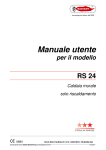
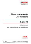
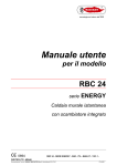
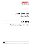
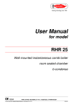
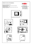
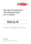
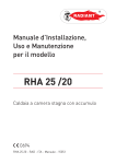
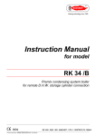
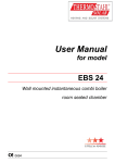
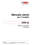
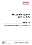
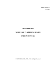
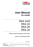
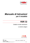
User Manual
for model
RS 32
Wall mounted heating only boiler
room sealed chamber
CE 0694
RS 32 - RAD - ING - MAN.UT - 1410.1 - DIGITECH TR - MIAH6 - E04
Technical specification RADIANT BRUCIATORI S.p.A. Montelabbate (PU) ITALY
ENGLISH
INDEX
1. General warning
pagina 1
2. Control Panel
pagina 2
3. Starting up the boiler
pagina 3
4. INFO Menu
pagina 3
5. Boiler functioning modes
pagina 4
6. Filling the system
pagina 5
7. Diagnostics – Error codes
pagina 5
8. Switching OFF the boiler
pagina 6
9. Frost Protection
pagina 6
10. Maintenance
pagina 7
11. Recycling
pagina 7
USER INSTRUCTIONS
BOILER OPERATING INSTRUCTIONS
1. General warning
Make sure that the authorised technician who tested the boiler has stamped the guarantee booklet.
The installation, first start-up, regulation and maintenance operations must be carried out exclusively
by qualified personnel (e.g. Radiant authorised Service Centres). Incorrect installation can cause
damage to property and injury to persons or animals, for which the manufacturer will not be held
responsible.
During the installation, the technician must carry out the following checks:
■ The data on the data plate must correspond to that of the mains supply networks (gas, electricity, water);
■ The boiler must be regulated according to its designed use and performance;
■ The flue gas exhaust and combustion air intake system must be correctly installed and operational;
■ The exhaust gas discharge and ventilation systems must comply with the requirements of national and local
standards regardless of whether the boiler is installed indoors, outdoors or in its own cabinet (see section
“Reference standards”).
User general warnings:
If there is any doubt as to whether the appliance has been tested by an authorised technician, do not
attempt to start it. All maintenance and gas conversion operations MUST BE CARRIED OUT BY
PROFESSIONALLY QUALIFIED PERSONNEL.
Should any part of the boiler freeze-up, do not attempt to light it under any circumstances, but instead
call the Service Centre immediately.
The appliance’s combustion system must be checked every two years. This check includes testing the
efficiency of the boiler and must be carried out by authorised personnel possessing the qualifications
as required by current law.
Do not obstruct the ventilation openings in rooms where there are gas-burning appliances installed
(boiler, cooker, etc.)
Do not allow the appliance to be used by persons (including children) with reduced physical, sensory,
mental capabilities or with lack of experience and knowledge unless they have been viewed or
educated on the use of the appliance by the person responsible for its safety or anyone unfamiliar
with its operation;
The installation, operation and maintenance manual forms an integral and essential part of the
product and must be kept near the appliance always.
If you smell gas …
DO NOT ACTIVATE ANY ELECTRIC SWITCHES, TELEPHONES OR ANY OTHER DEVICE THAT MAY
GENERATE ELECTRICAL DISCHARGES OR SPARKS.
OPEN DOORS AND WINDOWS IMMEDIATELY TO CREATE A CURRENT OF AIR THAT WILL RAPIDLY
CLEAR THE ROOM.
CLOSE ALL GAS TAPS AND VALVES.
CALL FOR PROFESSIONALLY QUALIFIED PERSONNEL.
1
USER INSTRUCTIONS
2. Control Panel
CONTROL PANEL KEY
1.
2.
5.
HEATING TEMPERATURE SETTING BUTTONS
INFO BUTTON: PRESS ONCE TO DISPLAY TEMPERATURES AND INFO (see 2.8 INFO menu display); KEEP IT
PRESSED FOR 5 SECONDS (IN OFF MODE) TO DISPLAY THE LAST 5 ERRORS.
MODE SELECTION BUTTON: WINTER ONLY / OFF.
RESET BUTTON: ERROR RESET – FLUE TEST FUNCTION ACTIVATION (CHIMNEY-SWEEPER - KEEP IT PRESSED
FOR 7 SECONDS)
PARAMETERS VALUE SETTING BUTTONS
6.
7.
TERMINAL BLOCK FOR EXTERNAL WIRING
LCD DISPLAY.
3.
4.
7
Fig. 1
1
2
3
4
5
6
During the boiler operation the display can show 2 different power levels according to the flame
modulation of the boiler (see fig. 2)
50%
1 00%
Fig. 2
2
USER INSTRUCTIONS
3. Starting up the boiler
•
Check that the boiler is power supplied and that the gas feed valve, placed at the bottom of the boiler, is
open.
•
Switch on the boiler by using MODE SELECTION BUTTON
required.
and select the functioning mode
4. INFO Menu
Press the ‘
’ INFO Button to display the boiler data.
Once pressed, the parameter number will appear on the left side of the display and the associated
parameter value will appear on the centre of the display. Use ‘
Temperature setting to scroll the list of available data.
Press the ‘
’ and ‘
’ buttons of
’ INFO button to exit the display mode.
The list of available display data is the following:
Description
Parameter
d01
Outdoor temperature sensor
d02
Kd Thermoregulation value
d03
Low temperature circuit sensor (only with Zone PCB connected)
3
Heating
USER INSTRUCTIONS
5. Boiler functioning modes
“WINTER” mode
To switch boiler operation to “WINTER” mode, press the MODE SELECTION button
(‘3’ – fig. 1); The
boiler will only work for the Heating system. The “WINTER” mode setting of the boiler is signalled by the symbol
lit continuously on the control panel.
The automatic ignition system will light the burner every time there is a room heating demand. In this case, the
symbol
will flash on the control panel.
Regulating the heating temperature
The heating temperature is regulated by using ‘
fig. 1):
•
Pressing ‘
’ and ‘
’ buttons of
Heating temperature setting (‘1’ –
’ button, reduces the temperature.
• Pressing ‘
’ button, increases the temperature.
The range of temperature settings for the central heating runs from a minimum of 30°C to a maximum of 80°C (25
°C – 45 °C for under floor heating systems).
4
USER INSTRUCTIONS
6. Filling the system
In order to restore the water pressure of the system,
open the filling tap R (fig. 2) and check by means of a
pressure gauge M, that the pressure of the system
reaches the middle part of the green zone (which
corresponds to 1,2 bar, see fig. 3).
On completion, close the filling tap R (fig.2).
R
7. Diagnostics – Error codes
M
2
This paragraph contains a list of error codes that the
boiler may generate on the display together with the
relative indications and the operations that the user can
carry out to reset the boiler.
GREEN AREA
Code E01 Ionisation malfunction
1.5 bar
Check that the gas valve on the boiler and gas meter
are open. and that there is gas in the mains supply.
Press Reset button ‘
the error;
1.2 bar
’ on the control panel to reset
3 bar
0.5 bar
When the error code on the display disappears, the
boiler will restart automatically.
3
If the problem persists, Call the Service Centre.
Code E02 Safety Thermostat tripped.
Press Reset button ‘
’ on the control panel to reset the error;
When the error code on the display disappears, the boiler will restart automatically.
If the problem persists, Call the Service Centre.
Code E03 Air Pressure Switch Tripped. Call the Service Centre.
Code E04 Water Pressure Switch Tripped (
).
Check the water pressure in the central heating circuit. The reading on the pressure gauge M (see fig. 2),
located on the lower part of the boiler, must not be less than 1,2 bar.
If the pressure is less than 1,2 bar, top-up the system as described in paragraph “Filling the system”.
When the error code on the display disappears, the boiler will restart automatically.
If the problem persists, Call the Service Centre.
Code E05 Heating Sensor malfunction. Call the Service Centre.
Code E18 Inadequate circulation. Call the Service Centre.
5
USER INSTRUCTIONS
Code E21 General malfunction inside the printed circuit board.
Switch off the power supply at the main switch and then switch it on again;
When the error code on the display disappears, the boiler will restart automatically.
If the problem persists, Call the Service Centre.
Code E22 Parameter programming request.
Switch off the power supply at the main switch and then switch it on again;
When the error code on the display disappears, the boiler will restart automatically.
If the problem persists, Call the Service Centre.
Code E35 Flame detection malfunction.
Press Reset button ‘
’ on the control panel to reset the error;
When the error code on the display disappears, the boiler will restart automatically.
If the problem persists, Call the Service Centre.
Code E40 Electric power supply out of the operation range. Call the Service Centre.
Code F08 Frost protection function (central heating circuit) ON. Wait for the completion of the operation.
8. Switching OFF the boiler
To switch the boiler OFF, press
INFO button, the word OFF appears on the display. The central
heating frost protection system remains enabled.
If the boiler was previously ON, it is switched OFF and the fan overrun and pump overrun functions are
enabled.
N.B. If the boiler is to be left unused for a long period of time, the user must do one of the following:
Make the boiler safe by disconnecting all the power supplies (electricity and gas), and draining the heating
system;
Leave the boiler in standby, leaving the electricity and gas supplies connected and, consequently the frost
protection function.
9. Frost Protection
The boiler is protected from freezing by electronic board settings and special functions that provide the starting of
the burner to heat all the interested parts, when their temperature drops below the minimum preset values.
This function is enabled if:
– the boiler is electrically power supplied;
– the gas supply is open;
– the system pressure is that required;
– the boiler is not locked out.
In case of boiler parts locked out because of freezing, do not switch the boiler ON and immediately
call the Service Centre.
6
USER INSTRUCTIONS
10. Maintenance
In order to ensure that the boiler operates efficiently and safely, it is recommended that the appliance is inspected
by a suitably competent technician at least once a year.
A regular maintenance is always source in management system savings.
11. Recycling
The appliance packaging is mainly made of
recyclable materials.
The symbol indicates the inability to dispose of
this product as domestic waste.
The appliance and all its accessories must be
disposed of appropriately differentiated
in compliance with the relevant standards.
The correct disposal of this product will help to
prevent potential negative consequences for the
environment and people health.
7
RADIANT BRUCIATORI s.p.a.
Via Pantanelli, 164/166 - 61025 Loc. Montelabbate (PU)
Tel. +39 0721 9079.1 • fax. +39 0721 9079279
e-mail: info@radiant • Internet: http://www.radiant.it
THE TECHNICAL DATA AND MEASUREMENTS ARE PROVIDED FOR
INFORMATION PURPOSES ONLY AND ARE NOT BINDING. THE
COMPANY RESERVES THE RIGHT TO APPLY VARIATIONS WITHOUT
PRIOR NOTIFICATION. NEITHER WILL THE COMPANY BE HELD
RESPONSIBLE FOR ANY INACCURACIES IN THIS HANDBOOK
DERIVING FROM PRINTING OR TRANSLATION ERRORS. E+OEALL
RIGHTS RESERVED. NO PART OF THIS DOCUMENT MAY BE
REPRODUCED, MEMORISED IN ANY FILING SYSTEMS OR
TRANSMITTED
IN
ANY
FORM
WHATSOEVER,
INCLUDING
ELECTRONIC, MECHANICAL, PHOTOCOPIES, RECORDINGS OR ANY
OTHER MEANS WITHOUT THE COMPANY’S PRIOR WRITTEN
APPROVAL.