1
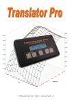
User Manual
Manual Version 1.0
Translator Pro version 4.4x
Table of Contents
Kit Contents:......................................................................................... - 3 Available Accessories and Options:..................................................... - 3 Introduction: ........................................................................................ - 3 Main Airflow Modes ............................................................................ - 4 Installation Details ............................................................................... - 6 Speed Density Installation. .................................................................. - 6 Translator Mode Installation............................................................... - 7 AFC Mode Installation. ....................................................................... - 7 Using the Keypad ................................................................................. - 7 Translator Pro Pages: .......................................................................... - 8 Speed Density Mode Setup................................................................... - 8 Speed Density Standard Connections................................................ - 10 Translator Mode Setup ...................................................................... - 10 Translator Mode Standard Connections ........................................... - 12 AFC Mode Setup and Standard Connections ................................... - 13 Parameter setting details for all pages: ............................................. - 14 Tuning with the Translator Pro......................................................... - 18 Open Loop vs. Closed Loop................................................................ - 19 Boost Control...................................................................................... - 20 AFR Tracking .................................................................................... - 21 TunerPro RT for tuning and logging (overview):............................. - 23 Speed Density Algorithm.................................................................... - 26 Glossary:............................................................................................. - 27 Translator Pro Harness Connector Details....................................... - 28 -
Translator Pro
User Manual
--2--
Kit Contents:
The Translator Pro kit is shipped with the following items.
Translator Pro unit
Standard splice harness, 10 pin
Standard splice harness, 6 pin
Serial cable for programming, tuning, and logging
CD ROM containing documentation, and software
Splice and tap connectors
Manual
Available Accessories and Options:
Boost control solenoid
Boost control harness (Plug-and-play and splice-in)
MAP (Manifold Absolute Pressure) sensor
IAT Sensor (Intake Air Temperature) sensor
Speed Density harness (Plug-and-play and vehicle specific)
Accessory power pack (offline power supply, 120VAC)
Introduction:
The Translator Pro is a powerful electronic module that allows the user
to tune the engine performance of a modern fuel-injected vehicle. The
unit is configurable for many different types of vehicles. Using its
various operational modes, the user can adjust fuel delivery, turbo
boost, and other operating parameters to extract more performance
from their vehicles' engine.
Warning: The Translator Pro is a powerful tool for adjusting the
operation of the engine. It is possible to mis-adjust the settings and
cause damage to the engine. The user must read and understand this
entire User Guide before attempting to install and use the Translator
Pro. Adjustments should be made in small increments with continuous
testing to ensure the engine is operating within its mechanical limits.
The primary function of the Translator Pro is to allow the user to adjust
the air-fuel ratio of their engine. This is accomplished by adjusting the
Translator Pro
User Manual
--3--
amount of airflow the Engine Computer Module (ECM) or Engine
Control Unit (ECU) perceives is entering the engine. If the ECM/ECU
senses less airflow is entering the engine, it will command less fuel be
injected into the engine, thus making the Air/Fuel ratio "leaner". If the
airflow signal is reduced by 1%, the resultant fuel delivery will be less
by 1%. For example, an engine is consuming 100 grams of air per
second, and the ECU is delivering fuel for 12:1 Air/Fuel Ratio (AFR).
If the airflow signal to the ECU is reduced to 95 grams per second (5%), the ECU will delivery fuel for this amount of air. The resulting
AFR will be 12.6:1 (5% leaner).
Main Airflow Modes
The Translator Pro sends airflow information in the form of an
electrical signal (voltage or pulse frequency) to the ECU. Frequency
signals are send on the green, "frequency out" wire of the 10 pin
harness. Voltage signals are sent on the Brown (V Out 1) or the Gray
(V out 2) wires of the 10 pin Main harness.
Speed Density Mode (MAF Eliminator)
The Translator Pro serves to replace the airflow sensing hardware on
the vehicle. The unit uses a sophisticated Speed Density algorithm to
calculate engine airflow based on external sensors. This airflow
calculation is used to synthesize a signal to send to the ECM/ECU, and
the vehicle's original airflow sensor can be removed.
MAF Translator Mode
The unit can be used to adapt a different airflow sensor to a vehicle. A
large, high performance MAF (Mass Airflow) sensor can be installed
on a vehicle not originally equipped with one, in order to increase
performance. The unit can be used to install a high flow MAF on cars
originally equipped with small, restrictive Karman Vortex or
mechanical/flap airflow meters. Examples include using a GM LS1 or
LS6 MAF on a Toyota Supra, Mitsubishi Eclipse, or Ford SVO
Mustang.
Airflow Computer Mode (AFC)
The unit can be used to adjust the signals from the vehicles originally
installed airflow sensor in order to tune the vehicles performance.
Translator Pro
User Manual
--4--
Translator Pro
User Manual
--5--
Pressure
Aux or O2/WB input
Frequency In
Intake Air Temperature
Manifold
TPS
RPM
Density Calculations
Airflow
Source
User Tune
High Load / RPM
Mid Load / RPM
Low Load / RPM
Air Temp Corrections
Aux Mode / RPM
RPM
TPS
Frequency In
High Load / RPM
Mid Load / RPM
Low Load / RPM
Air Temp Corrections
Aux Mode / RPM
User Tune
Gain
Limits
Target AFR / RPM
AFR Tracking
Volt Out
Freq Out
AFC Mode. Set F Out Mode to 0
Select Speed Density or Translator mode
MAF Input
(Analog or Frequency)
Volumetric
Efficiency
Response Tuning
Afterstart
Correction
Engine displacement
Engine # of cylinders
Speed
Gain
Limits
Target AFR / RPM
AFR Tracking
Volt Out
Freq Out
Installation Details
This section contains installation details that are not specific to any
particular vehicle. Please refer to the appendix and other installation
diagrams contained on the CD included in the Translator Pro kit.
Harness connections are referred to by connector designation M, S, E,
(Main, Sensor, and Expansion) and pin number, for example the +12V
main power input is connected to the pink wire at M5, Ground at M10.
In this manual, TAP means to connect to a harness wire without
cutting it. Splice means to cut a harness wire and connect Translator
Pro wires to the cut ends.
Wire Splicing and Tapping information
The Translator Pro is installed by connecting wires into the vehicle's
wiring harness. Good connections are absolutely necessary for proper,
reliable operation. A loose or intermittent connection could cause
improper fuel delivery at full throttle resulting in engine damage.
Squeeze style tap connectors are included in the kit due to their
popularity, but are not the most reliable means of connection. To use
the squeeze style properly they must be installed firmly. Regular slipjoint pliers are best for this. If there is doubt about the users ability to
install the squeeze taps properly, or the wiring area is subject to
vibration, soldering the connections is recommended.
The pink spade connectors included in the kit are of the best quality and
will provide good reliability when properly crimped. Inexpensive
crimpers may not crimp firmly enough. Tug on the crimped connection
to ensure there is no looseness and the wire does not pull out. When in
doubt, solder the connections.
For additional details on soldering the connections, refer to this guide:
http://www.mmxpress.com/technical/connections.htm
Speed Density Installation.
Using a speed density harness, install and connect a MAP sensor and
IAT sensor. The MAP sensor needs to be installed using a piece of
vacuum hose connected to the intake manifold plenum. The sensor
must read vacuum in order to properly control fueling at idle and part
throttle. If the vacuum source is too close to an individual cylinder,
the vacuum will fluctuate excessively, resulting in poor drivability. The
IAT should be installed so that its sensing element can read the
temperature of the air entering the engine. On turbocharged vehicles
Translator Pro
User Manual
--6--
this is usually the pipe that leads from the intercooler to the throttle
body. The sensor can be installed in the intake manifold, but the
possibility of "heat soak" is increased.
Remove the MAF sensor from the vehicle and install an air filter on the
inlet duct. If a vehicle specific harness is being used, refer to those
instructions for wiring details. Otherwise use a universal Speed
Density harness or wire the sensors directly to the splice harness
included with the Translator Pro kit. Install the Translator Pro wiring,
splicing in to the MAF signal wire so the Translator Pro can alter its
signal. If the original MAF had extra signals, wire the analog outputs
to those ECU wires so the Pro can generate those signals. Tap the TPS
and RPM signals.
Translator Mode Installation.
Remove the vehicle's original MAF and install the upgraded MAF. If a
plug-and-play harness is available, follow the instructions specific for
it. Otherwise wire the new MAF such that the signals use the original
vehicle wiring. Install the Translator Pro wiring, splicing in to the
MAF signal wire so the Translator Pro can alter its signal. If the
original MAF had extra signals, wire the analog outputs to those ECU
wires so the Pro can generate those signals. Tap the TPS and RPM
signals.
AFC Mode Installation.
Install the Translator Pro wiring, splicing in to the MAF signal wire so
the Translator Pro can alter its signal. Tap the TPS and RPM signals.
Using the Keypad
The Translator Pro is equipped with a 5-key keypad and LCD to allow
the user to make tuning adjustments to the unit without needing a
laptop computer or other external device. Most tunable parameters are
accessible from the keypad. There are 3 main sets of data that are
manipulated with the keypad: page, range, and setting. The page is
selected by holding the PG (page) key, then pressing either RangeUp
or RangeDn to select the desired page. The page description is
displayed while PG is depressed. On any page, the RangeUp and
RangeDn select the range to be adjusted, SetUp and SetDn change the
setting of that range.
For example, to adjust the airflow (and consequentially the air/fuel
ratio) at idle, select the AF Lo page by holding PG and using
RangeUp or RangeDn to select the Airflow Low page. Then use the
Translator Pro
User Manual
--7--
RangeUp or RangeDn key to select the RPM range that s closest to idle
speed. Then use the SetUp or SetDn keys to adjust the setting.
The Config and Setup pages are used to configure the unit for a specific
kind of car and airflow mode. These pages require an extra step to gain
access in order to prevent inadvertent changes. To enable access to the
Config and Setup pages, hold the PG button depressed for 10 seconds
until the display shows "Config Enabled". Then these pages can be
used to configure the Translator Pro.
Translator Pro Pages:
Use these pages to set the operating modes for your specific vehicle
configuration
Config Select: Set the unit for the vehicle and sensors connected
System Setup: Settings related to the selected configurations
Boost Control: Settings using the boost control output on the EXP
connector
AFR Tracking
Air Temp: User AF tune vs. IAT, this adjustment is in addition to the
normal compensation
Aux Trig: User AF tune that is activated when the AUX input is
activated
AF Hi: High load AF tune vs. RPM.
AF Mid: Mid load AF tune vs. RPM
AF Low: Low load AF tune vs. RPM
Response: Adjustments for response to changes in MAP and TPS (tipin) (Speed Density only)
Sensor Monitor: Display operating and tuning parameters.
Spark WOT: Adjust WOT (Wide Open Throttle) spark advance (not all
vehicles)
Spark Aux: Adjust WOT (Wide Open Throttle) spark advance when
AUX mode is activated (not all vehicles)
Speed Density Mode Setup
The Translator Pro is a high-tech engine tuning device that fills the
technology gap between the popular but simple piggyback tuning
devices and the full-blown, expensive standalone engine management
systems. The Translator Pro uses sophisticated computations to
determine engine airflow, thus relieving the user of the daunting task of
completely mapping the engine s operation. Once the initial setup is
Translator Pro
User Manual
--8--
complete, there is usually little tuning required to attain smooth
operation and drivability.
The Engine Control Module (ECM) or Engine Control Unit (ECU) in a
vehicle is a small computer unit responsible for calculating how much
fuel is injected into the engine. The fuel is injected to match the air
flowing into the engine. The Translator Pro, like traditional
piggyback controllers allows the user to adjust the airflow
measurement, thus changing how much fuel the ECM/ECU injects into
the engine. This is how the user tunes the engine. The Translator
Pro is unique in that it allows the user to remove air measurement
devices (MAS, MAF, VAF, etc) from the engine and use a speed
density calculated signal to replace it. In high performance engine
applications this has many advantages and added flexibility.
To enable Speed Density mode enter the engine and sensor parameters
in the Config and Setup pages. The Translator Pro uses the engine
parameters to calculate the airflow. Then set Airfl Srce (Airflow
Source) to 0 or 1 so the Translator Pro will calculate airflow via the
speed density algorithm. Use 0 if the ECU is not getting temperature
information via another signal. Use 1 if the ECU is receiving air temp
information and will compensate its fuel delivery. Some vehicles have
MAF sensors with other functions or signals. These other signals are
typically Barometric pressure and Air Temperature. These MAF
sensors are actually "Air Volume" sensors, and the ECU uses the
temperature and pressure data to calculate the airflow mass. When
using a calculated airflow mass (speed density) the air temp and baro
signals must be kept constant to prevent double-compensation. These
other signals can be simulated by the Translator Pro, using the V Out 1
and V Out 2 signals. Set the V out 1 and 2 mode to 0 in the Config
page, and set the output voltages to normal levels in the Setup page. If
the vehicle ECU requires a voltage MAF signal (Ford, some Toyota,
etc) connect Analog Output 1 to the ECU MAF input and configure V
Out 1 mode for the correct analog MAF signal calibration.
Translator Pro
User Manual
--9--
Translator Pro
User Manual
Ground
Sensor Signal
5 Volt
Sensor Signal
Ground
8 7 6
3 2 1
Connect to intake manifold
vaccuum source
A
B
C
A
B
10 9
5 4
IAT Sensor
Frequency Output Select with F Out Mode
To ECU MAF input
RPM input (5 volt signal)
TPS Input
Wideband/O2 Ground
Wideband/O2 input
Purple wire for Aux
trigger or logging
external signal
Analog output 1
Set with V Out 1 Mode
Ground
12 Volts
on with ignition
Speed Density Standard Connections
6 5 4
3 2 1
LCD Contrast
Serial port
MAP Sensor
Translator Mode Setup
- - 10 - -
8 7
4 3
6
2
In Translator Mode a vehicle can be equipped with a larger high
performance MAF than was originally installed. The new MAF is
installed and wired to the Frequency Input (for GM style frequency
MAFs) or to the AUX input (for Ford style voltage MAFs) To enable
Translator Mode, the F In Mode (for Frequency MAF) or AUX 1 mode
are set to the proper setting for the new MAF. The F out mode or V out
mode is set to match the vehicle, so the airflow output signal scaling
will match the vehicle. Then set Airfl Srce (Airflow Source) to 10 or
11 so the Translator Pro will use the MAF sensor input as the signal
source. Note: using setting 11 requires a custom VE table for proper
operation. Most applications will use setting 10. Some vehicles have
MAF sensors with other functions or signals. These other signals are
typically Barometric pressure and Air Temperature. These MAF
sensors are actually "Air Volume" sensors, and the ECU requires the
temperature and pressure in order to calculate the airflow mass. When
using a true MAF sensor, the air temp and baro signals must be kept
constant to prevent double-compensation. These other sensors can be
simulated by the Translator Pro, using the V Out 1 and V Out 2 signals.
Set the V out 1 and 2 mode to 0 in the Config page, and set the output
voltages to normal levels in the Setup page.
Frequency or Voltage MAF
RPM
Throttle Position (TPS)
ECU inputs
Voltage outputs
if required
Translator Pro
User Manual
- - 11 - -
Translator Pro
User Manual
Connect MAP input to TPS when
no MAP sensor is installed
input
Ground
8 7 6
3 2 1
Wideband/O2
Wideband/O2
10 9
5 4
TPS Input
Frequency Output: Select with F Out Mode
To ECU MAF input
Purple wire for Aux trigger Analog MAF input:
Select with Aux 1 Mode
RPM input (5 volt signal)
Analog output 2 Set with V Out 2 Mode
Analog output 1 Set with V Out 1 Mode
Ground
MAF Input (Frequency Input 1)
12 Volts
on with ignition
Translator Mode Standard Connections
6 5 4
3 2 1
LCD Contrast
Serial port
- - 12 - 8 7
4 3
6 5
2 1
AFC Mode Setup and Standard Connections
To enable "AFC" mode set F OUT Mode to 0 in the Config page so
the Translator Pro will use the MAF sensor input as the signal source.
Some vehicles have MAF sensors with other functions or signals.
OEM Frequency MAF
RPM
Throttle Position (TPS)
ECU input
Purple wire for Aux trigger or logging
Select with Aux 1 Mode
RPM input (5 volt signal)
Ground
MAF Input (Frequency Input 1)
12 Volts
on with ignition
IAT and/or BARO sensors
LCD Contrast
Translator Pro
User Manual
input
Serial port
Connect MAP input to TPS when
no MAP sensor is installed
Wideband/O2
Ground
6 5 4
3 2 1
Wideband/O2
8 7 6
3 2 1
TPS Input
Frequency Output: Select with F Out Mode
To ECU MAF input
10 9
5 4
- - 13 - -
8 7
4 3
6
2
Parameter setting details for all pages:
Config:
Vehicle Select: Select 1 if unit is wired to stay on for 10 seconds after
key-off (Mitsubishi).
# of Cyl: Set to the number of cylinders of the engine,
(exception: 96+ LT1, LS1 set to 4)
Displ: Displacement in Liters
Airfl Srce: source for airflow to output signal
0 - Speed Density with temp compensation
1 - Speed Density without temp compensation
10 - MAF input with UserTunes (Translator Mode)
11 - MAF input with UserTunes and VE table (Translator Mode)
MAP Source: Select type of MAP sensor
0- GM 3 bar sensor
1- AEM 3.5 bar sensor
2- AEM 5 bar sensor
3- GM 2 bar sensor
4- Motorola 2.5 bar sensor
Dens Srce: Future select input and scaling for IAT
Baro Mode: Select Barometric Pressure mode
0 - No BARO mode, use Sealevel value to calculate boost, no fuel change
1 - Detect Baro at key-on, use to calculate boost, no fuel calculation change.
F-Out mode: Select function and scaling of Frequency output
0 - AFC MODE, with UserTunes
1 - 1G DSM
2- EVO-8 and 3G DSM
3- 2G DSM and 3000GT/Stealth
4 - Supra MK-III
5- LS1 Aluminum MAF, F-Body
6- LS1 Truck
8 -GN (Extreme and Extender Pro)
9 -GN (Extender chips)
10 -GN (Commander chips)
11 -GN(Stock style)
12 - LT1 (3" MAF) Impala SS, and passenger
car
13 - LT1 (3.5" MAF) LT1 and LT4 F and Y
body cars
30 - Ford BAP sensor signal, fixed at sealevel
setting.
7- LS1 (future application)
V-Out1 mde: Select function and scaling of Volt out 1
V-Out2 mde: Select function and scaling of Volt out 2
0- use volt setting in Setup page
1- WOT Spark control signal for GN
and DSM
2- 2 bar MAP sensor simulation
6- Mitsubishi air temperature sensor
simulation
10- Toyota Supra MK-IV MAF
output
Translator Pro
User Manual
11- Ford Cobra MAF output
12- Ford Cobra (62lb modified) MAF output
13- Ford SVO/Merkur VAF output
14- GM TPI voltage MAF output
50- Ford custom
- - 14 - -
AFR Source: Select scaling of wideband input
0 - none
1 - LC1
2 - LM1
4 - Tech Edge (Australia) Wideband
5 - Zeitronix ZT2 Wideband
6 - Dynojet Wideband Commander (0-5 volts =
10:1 - 16:1)
3 - AEM, AFM-1
0 volts@10:1 5 volt @ 20:1
F-In Mode: Select scaling of Frequency Input (Prescaler setting)
0 - Frequency input, no scaling (OFF)
1 - 3" GM MAF (ON)
2 - 3.5" GM MAF (ON)
3 - 85mm GM MAF, no screen (ON)
4 - Extreme GM MAF (ON)
5 - Buick GN Translator output,
Extreme mode (OFF)
6 - 85mm GM MAF, with screen (ON)
7 - 3.5" GM LT1 MAF (ON)
20 - Timing Monitor Mode for Supra
(Off)
21 - Timing Monitor Mode for Turbo
Buick GN (Off)
22 - Timing Monitor Mode for
3000GT/Stealth (Off)
23 - Timing Monitor Mode for DSM and
EVO (Off)
31 - VE tuning during AFC mode, 1G
DSM (Off)
32 " EVO 8 (Off)
33 (Off)
34 -
" 2G DSM, 3000GT/Stealth
" MK-III Supra (Off)
* The Prescaler is the config jumper inside the unit, ON is the left 2
pins, OFF is the right 2 pins. Position the jumper according to the
above chart.
Aux1 Mode: Determines function of Aux trigger wire
(Sensor Harness, pin 6, purple wire)
0 - Aux triggering disabled
1 - Aux triggering activated by applying voltage to the AUX wire
2 - AUX triggering DE-activated by applying voltage to the AUX wire
3 - AUX triggering is activated at all times
30 - Read EGT signal on AUX wire, Aux trigger function remains off
31 - Read EGT signal on AUX wire, Aux trigger function activated
200 - Read Analog MAF on Aux trigger wire. Mustang Cobra
201 - Read Analog MAF on Aux trigger wire. Custom Ford
F Out Max: set for the maximum frequency that will be sent out the
MAF output. Can be used to prevent fuel-cut, or intentionally lean out
the top end. Set to 0 to disable frequency limiting.
Setup:
Mainscale: adjusts the entire range by the same %
V-Out1 set: Setpoint for V-Out1 in Mode 0
V-Out2 set: Setpoint for V-Out2 in Mode 0
Afterstart: Enrichment for the first few minutes of engine run time
Translator Pro
User Manual
- - 15 - -
Lo Load Pt: KPA for the Lo Load User tunes
Mid Load Pt: KPA for the Mid Load User tunes
Hi Load Pt: KPA for the Hi Load User tunes
Tm Base: Adjustable in degrees to match the Timing Monitor reading to
actual
Tm Correct: Adjust to make Timing Monitor match both low and high RPM
AF TrDelay: Adjustable delay of 0-25.5 seconds that AFR tracking
waits after enabled, before it begins to correct.
Boost Control
The Translator Pro can control turbocharger boost pressure when the
optional boost solenoid is installed. See the separate section on Boost
Control.
AFR Tracking
The AFR Tracking page is used to control how the Translator Pro selfadjusts to maintain a desired AFR at WOT. The Translator Pro does
not self-tune, but will correct its output while at WOT. See the separate
section on AFR Tracking.
Air Temp
Air temp correction, setting is added to the regular system tune value.
Note this adjustment is in addition to the Speed Density algorithm's
temperature compensation. Additional adjustment can be required to
adjust for atomization characteristics of injectors, or heat-soak
conditions.
Aux Triggered
At each RPM point, the set tune percent is added to the High Load user
tune when the Aux Trigger input is activated.
Tune High
Tune Mid
Tune Low
User tune values, load points are determined in the
Setup page. These settings are blended between RPM
and load points and added to the System Scale, Air
Temp, and Aux Trigger settings.
Tune Response
The response page in the Translator Pro is for adjusting the unit to add
a small burst of extra fuel when the throttle is opened. Anyone who has
tuned a carburetor would call this an "accelerator pump", and its
operation is similar. The Response tuning only affects Speed Density.
Translator Pro
User Manual
- - 16 - -
Sensor Monitor
Displays various sensor and system signal values. Range buttons select
the 2 left displays, Set buttons select the right 2 displays. The TOP
RIGHT displayed value appears on all other tuning pages. If the Top
Left and 2 bottom displays are all set to the same parameter, the bottom
display becomes a bargraph display for that value.
RPM
MP
DC
AFL
AFI
VE
Cel
FI
F0
UT
TPS
BD
MT
Engine RPM
Manifold Absolute
Pressure (KPA)
Density compensation, %
correction from air
temperature (Speed
Density mode)
Airflow, Grams/sec (Speed
Density mode)
Airflow input
( Translator mode)
Volumetric Efficiency
(Speed Density mode)
Active Cell in VE table
(1-255)
Frequency input (Hz)
Frequency Output (Hz)
User Tune, the total of the
tune and mainscale
Throttle Position Sensor.
0-5 volts
Boost Dutycycle
Manifold Temperature
(IAT) (degrees F)
Translator Pro
User Manual
O2
O2/Wideband input voltage
FE
Flow Error, depends on mode
ASC
Afterstart compensation %
AFR
Air Fuel Ratio if wideband O2
connected
CF
AFR tracking Correction Factor %
TAF
Target AirFuel Ratio for AFR Tracking
Spk
Spark Advance desired (GN/DSM)
BA
BP
Barometer, read at key-on if enabled
Boost Pressure (+/- psi)
Aux input #1 voltage (purple wire, 6
pin connector)
Ax1
TM
Timing Monitor (Degrees)
Rs
Response fuel.
32 - 1800 degrees F (when using EGT
accessory, wired to Aux input)
EGT
- - 17 - -
Spark WOT
At each RPM point, the Spark advance that is programmed is what the
vehicle ECU will run once boost is over approximately 6 psi. This
feature only works on vehicles specifically set up for Remote Spark
Advance Control. Currently this is only DSMChips equipped cars with
this feature activated, and Buick GN's running the Extender Pro chips.
Spark AUX
The Spark advance programmed into this page will be used instead of
the WOT Spark if the Aux input is triggered. (DSMChips equipped
cars with this feature activated, and Buick GN's running the Extender
Pro chips only)
Tuning with the Translator Pro
Generally, once the Translator Pro is properly configured, the engine
should start and run. Then the next step is tuning. "Tuning" is the term
used to describe adjusting the fuel delivery and spark advance (as well
as other items) for best operation of the engine and vehicle.
Tuning is accomplished using the Translator Pro keypad. Air/Fuel ratio
(AFR) is adjusted in the low/mid/high load tuning pages. "Load" refers
to how hard the engine is working at a certain RPM. Low load means
light throttle operation, idle, and steady speed driving. Mid load refers
to easy acceleration at moderate throttle. High load refers to heavy
throttle acceleration.
The tuning is identical for all modes, Speed Density, Translator, and
AFC.
The AFR tuning is the sum of the Mainscale, low/mid/hi/aux User
Tune, and Air Temp tune settings. This total can be viewed on the
Sensor Monitor page as UT (User Tune). Adjust the Mainscale initially
for the best compromise between idle and part throttle driving. This
sets the tune "close". Then use the low load page to adjust the tune at
idle and light throttle driving. The mid load adjustments should be set
for proper AFR for moderate acceleration. The mid load settings at 800
to 1200 RPM also affect "tip-in" smoothness. Hi load adjustments are
used to adjust the AFR for WOT operation.
Translator Pro
User Manual
- - 18 - -
Open Loop vs. Closed Loop
Modern engine control systems operate in "closed loop" during part
throttle operation. The ECU measures the signal from the Oxygen
Sensor, mounted in the exhaust system, and makes internal fuel
delivery corrections to maintain 14.7:1 AFR. Adjusting the Translator
Pro when the ECU is operating closed loop will not affect the AFR,
since the ECU will re-correct back to 14.7:1. This effect can be seen
by monitoring the ECU controlled variables using a "Scan Tool "or
"Datalogger". Tuning part throttle, closed loop operation is
predominantly adjusting for consistent "trim" or "BLM" values.
During warm-up and WOT operation the ECU operates in "open loop"
mode, and tuning changes directly affect the AFR. Refer to the
technical documentation specific to your vehicle for more details.
Response tuning (Speed Density only)
The response page in the Translator Pro is for adjusting the unit to add
a small burst of extra fuel when the throttle is opened. Anyone who has
tuned a carburetor would call this an "accelerator pump", and its
operation is similar. There are 2 main inputs to the response
adjustments. TPS, the Throttle Position Sensor, this signal is 0 to 5
volts and is the blue wire in the ECU/ECM harness (10 pin plug).
MAP, Manifold Absolute Pressure, which is 0 to 5 volts from a sensor
(MAP sensor) that is wired into the green wire of the Sensor harness (6
pin plug).
When the throttle is opened quickly (or even slowly) the TPS signal
changes because the sensor is physically connected to the throttle. The
MAP signal changes because the vacuum in the intake manifold drops
or boost increases. When this happens, the airflow signal to the
ECU/ECM must be increased slightly for a short period of time to
prevent hesitations or stumbles.
For the TPS triggered enrichment there are 3 adjustments TPS Enrich,
TPS decay, and TB Size.
For the MAP triggered enrichment there are 2 adjustments MAP Enrich
and Boost Enrich.
The Enrich setting controls the amount of extra fuel added when the
throttle is opened. The amount that is added depends on how high the
setting is, and how fast the throttle is opened. Setting this value higher
Translator Pro
User Manual
- - 19 - -
results in more fuel being injected.
The TPS Decay setting controls how quickly the extra fuel is reduced
back to zero after the TPS stops changing. A higher number results in a
shorter duration of enrichment. TB Size changes the relationship
between the throttle position and the effect of the Enrich setting.
Higher numbers for TB size shift the Enrichment to lighter throttle
positions.
When using both TPS and MAP enrichments, the resulting fuel
enrichment is not the sum of the enrichments, but the Translator Pro
uses whichever enrichment is greater. Tuning method is basically
setting the adjustments for best drivability. It is easy to set the
adjustments too high and get stumbles from a rolling punch while still
having good stoplight manners. So the best strategy is to use the
smallest enrichment that results in good drivability, not the largest. The
"Spare" settings on the response page are for future use, and have no
effect.
Boost Control
The Translator Pro controls turbocharger boost by operating the solenoid
with a "Dutycycle", which is the ratio of the time the solenoid is
energized, to the time it is off. 100% Dutycycle means the solenoid is
full on. 50% Dutycycle means the solenoid is being turned on and off
with equal timing. 10% Dutycycle means that the solenoid is on briefly,
then off for much longer. Refer to the instructions included with the
solenoid when installing the solenoid.
The Translator Pro controls boost as follows: During normal driving,
the solenoid is not activated. When the Throttle and RPM thresholds are
exceeded, Spool mode is activated, and the solenoid is fully energized
(100% dutycycle) which prevents any pressure from passing thru the
solenoid and causes the turbo to spool as quickly as possible. Once the
boost pressure exceeds "PSI Start" the solenoid is operated at the "Start
DC%". If the boost pressure exceeds the desired target boost "PSI Set"
(or "PSI Aux" if the Aux input is activated) the solenoid dutycycle is
reduced at a rate determined by the "Gain" setting. The solenoid
dutycycle will only be increased to raise the boost if the throttle position
exceeds "TPS Start"
Translator Pro
User Manual
- - 20 - -
The Translator Pro can control the boost pressure to a desired setting as
long as a MAP sensor is connected to the unit. Adjust the Boost Control
parameters as follows:
TPS Spool: Throttle sensor voltage to enable Boost Control. Usually
adjusted to 1.25 - 2.5 volts. Lower settings can improve spoolup time.
Higher settings can reduce part throttle surge. It should be set higher
than typical cruising TPS voltages.
RPM Spool: Engine RPM to enable Boost Control. Set higher than
typical cruising RPM.
TPS Start: Once Boost control has started, TPS must exceed than this
for the system to increase solenoid duty cycle. Set this to about 80%
throttle. If it is set too low, the Translator Pro will attempt to raise the
boost pressure as the driver "backs out" of the throttle. If the driver
were to floor the throttle again a boost spike could occur.
PSI Start: Boost pressure at which the system changes from Spool
mode (solenoid full on) to Start mode. Set this half way between the
base boost of the vehicle and the desired boost. If boost overshoots are
excessive, reduce this setting. If boost overshoot is desired, set this
closer to the target boost.
DC% Start: The Solenoid dutycycle that is set when spool mode
completes. The approximate setting to start with is(1-(base boost/target
boost))*100. First tests should start with about half of this. Example,
base pressure = 10 psi, target boost = 18 psi. Estimated Dutycycle
=(1-(10/18)) * 100 = 44%. So start at 22% for initial testing.
PSI Set: Boost Pressure the system will try to maintain
PSI Aux: Boost Pressure the system will try to maintain when the Aux
Trigger input is activated.
Gain: How fast the system will change the solenoid dutycycle to try to
adjust the boost. Set this only high enough to achieve good boost
control. Too much gain will cause the boost to surge/oscillate. Setting
the Gain to 0.0 will prevent the system from adjusting the solenoid to
control boost.
DC% Aux: The Solenoid dutycycle that is set when spool mode
completes and Aux mode is activated.
AFR Tracking
The Translator Pro can control WOT AFR to a desired setting using
feedback from a wideband AFR sensing device. Install the wideband
sensor in the exhaust following the manufacturer s instructions.
Connect the Translator Pro wideband/O2 input to the analog output of
Translator Pro
User Manual
- - 21 - -
the wideband unit. Connect the wideband/O2 sensing ground to the
wideband ground. (use the "analog ground" if the wideband has one, or
connect to the wideband main ground, close to the unit) The
wideband/O2 sensing ground must be connected or the wideband signal
will not be measured correctly. The wideband input on the Translator
Pr is a "differential input" and measures the difference between the
input and the sensing ground. Set the AFR Source in the Config page
to match the wideband unit installed. Setup or program the wideband
unit if required.
When the wideband unit is installed and operating the analog voltage
can be monitored on the O2 parameter of the Sensor Monitor page, and
the AFR is also viewable. Ensure the AFR displayed matches the
wideband unit.
The AFR tracking page is adjusted for WOT AFR control as follows.
Min TPS: - TPS above which the AFR tracking is enabled. Set this
high enough to ensure the ECU will be operating Open Loop whenever
AFR tracking is enabled.
Min RPM: - RPM above which the AFR tracking is enabled. Set this
high enough to ensure the ECU will be operating Open Loop whenever
AFR tracking is enabled.
Min MAP: - Manifold pressure above which AFR tracking is enabled.
Set this high enough to ensure the ECU will be operating Open Loop
whenever AFR tracking is enabled.
Lean Lim%: - The maximum % that the system will lean out to
maintain the desired A/F. It is advisable to set this around 5%, so the
AFR will not go incredibly lean if there is a problem with the wideband
unit.
Rich Lim%: - The maximum % that the system will richen up to
maintain the desired A/F. This can be fairly high (25%) to help protect
the engine in case of a fuel system partial failure.
Gain: - The speed that the system will try to maintain the desired A/F
ratio. Start with 5, and test the operation of the tracking. Setting this
too high will result in unstable AFR and a system that "oscillated
AFR 2000R ... AFR 8000R Desired A/F Ratio at each RPM from
2000 RPM to 8000
Aux% - Change to target AFR when Aux is activated
(there is a "AF Trk Dly" parameter on the Setup page which controls a
delay from when the enabling conditions are true to when AFR tracking
begins.
Translator Pro
User Manual
- - 22 - -
TunerPro RT for tuning and logging (overview):
The Translator Pro kit contains a CD ROM with additional
documentation details and the TunerPro RT software. TunerPro RT
requires 32 bit Windows, Windows 98 or later. TunerPro RT can be
used to upload tune files into the Translator Pro, or download your tune
data for saving and sharing. To install TunerPro RT, copy the
installation "Setup" file to your hard disk (in most versions of
Windows, you can simply drag it onto the "desktop"). Double click on
the Icon and install the software using all of the default settings. This
will install TunerPro RT into C:\Program Files\TunerPro RT. This is
the base directory/folder. Most of the settings that control TunerPro
RT are preset in the version distributed with the Translator Pro. So
only those operations required to use this version are included here.
The Translator Pro must be powered in order to communicate with
TunerPro RT. An accessory power pack is available to power the
Translator Pro when not installed in the vehicle.
To upload and download the tuning data, called BIN files, do the
following:
Use the XDF menu to select the correct XDF file, located in
the bin definitions directory/folder. For Translator Pro version
4.40, use TPRO4400.xdf. This will provide TunerPro with the
data necessary to properly display the tuning data in the BIN
file.
Use the File menu to select the correct BIN file, located in the
bins directory/folder. The BIN file contains the tuning data.
Once TunerPro has been configured, refer to the screenshot below.
Once you have made a change to a tune setting, be sure to Save or Save
As the BIN file. Then the BIN must be Uploaded to the Translator Pro.
Changes made in the computer are not automatically transferred to the
Translator Pro (unless in Emulating mode, an advanced topic, not
covered here)
Translator Pro
User Manual
- - 23 - -
To log with TunerPro configure the software as follows.
Use the Configure ALDL button to open the Configure
window.
Translator Pro
User Manual
- - 24 - -
Select an ADS file from the datastreams folder. The filename
should match the XDF file. If a XDF ADS mismatch error is
displayed, it is still ok to continue.
Select a filename to save the log data to. If one does not yet
exist, enter a new filename and click Open, then confirm (Y)
to create a new file.
Close the config window
Click the Connect button
Click the M for monitor traces, D for a dashboard display.
Right clicking on a logging area allows selection of available
data for that display area.
To record a log, click the red circle, stop recording by
clicking the black square, and enter session comments.
Each time a log is recorded it is stored as a session in the
logfile.
Translator Pro
User Manual
- - 25 - -
Speed Density Algorithm
Speed Density calculates engine airflow as follows. Consider a
theoretical 4 Liter engine for the following explanation. The engine
can be thought of as a pump that, at 100% efficiency, will move 4 liters
of material from its inlet to its outlet every 2 revolutions or the
crankshaft. At idle the efficiency is mainly controlled by the throttle
blade and somewhat by the camshaft/valve timing. At heavier throttle
the efficiency is mainly affected by the camshaft and valve timing and
mechanical efficiencies of its construction. The material that is being
moved by this pump is air of varying pressure and temperature. Since
we can measure the pressure and temperature of the air entering this
engine, we can calculate the air being pumped through if we know the
efficiency. This efficiency is known as the Volumetric Efficiency
and is the main tuning element of the Translator Pro s Speed Density
algorithm. The Translator Pro then uses the calculated airflow number
to generate an airflow signal to send to the ECM/ECU. The ECM/ECU
is unaware that the air measurement is coming from the Translator Pro
instead of the original measurement device, and will deliver fuel based
on the new airflow signal.
Volumetric Efficiency (VE) is the main tuning element in the Speed
Density system. VE is generally around 45 to 55 percent at idle. At
mid and heavy throttle the VE is highest (85 to 95 %) at peak torque
RPM. VE tends to fall at high boost and RPM on turbocharged
vehicles due to turbo backpressure. On the Translator Pro, the VE table
is preprogrammed, but can be easily changed using the PC interface
program. The default VE table is close enough for most applications,
and the keypad tuning methods can be used to fine-tune the system.
Translator Pro
User Manual
- - 26 - -
Glossary:
AFR
WOT
ECU
ECM
VE
TPS
MAF
IAT
RPM
UT
OEM
Translator Pro
User Manual
Air Fuel Ratio.
Wide Open Throttle
Engine Control Unit
Engine Control Module
Volumetric Efficiency
Throttle Position Sensor
Mass Airflow Sensor
Intake Air Temperature
Revolutions Per Minute
User Tune
Original Equipment
Manufacturer
- - 27 - -
Translator Pro Harness Connector Details
LCD Contrast
10 9 8 7 6
5 4 3 2 1
6 5 4
3 2 1
Serial port
8 7 6 5
4 3 2 1
Main (10 pin) Harness
8 7 6
3 2 1
10 9
5 4
1
2
3
4
Orange --
O2/wideband input.
Purple -- O2/wideband sensing ground
Blue -- TPS input
Green -- MAF/Frequency signal output
5
6
7
8
9
10
Pink -- +12 volts ignition power
Brown -- Voltage signal output #1
Gray -- Voltage signal output #2
White -- RPM signal input
Yellow -- MAF / Frequency signal input
Black -- Ground
Sensor (6 pin) Harness
6 5 4
3 2 1
1
2
3
4
5
Red -- 5 Volts to power the MAP sensor
Green -- MAP Sensor Signal
Brown -- Air Temperature Sensor signal
Black -- Ground
Black -- Ground
Purple -- Aux activation
6
Expansion (8 pin) Harness
8
4
7 6 5
3 2 1
1
2
3
4
5
6
7
8
Translator Pro
User Manual
Pink -- +12 volts out to Boost Solenoid
Purple -- Boost Solenoid control signal
- - 28 - -
Updating the Translator Pro software
The update procedure requires 32 bit Windows, Windows 98 or later.
Copy the update files to your hard disk; the exact location is not critical
as long as all the files are together. These files are as follows:
Update.exe -- This is the program that sends the new software
Tproxxx.S19 -- This is the update file
loadxxx.bat -- This is a "batch file" which has the series of commands
to make Update.exe load the file into the Translator Pro. There are
several versions of this file depending on which COM port is connected
to the Translator Pro. Connect the Translator Pro to the computer
using the black cable that is included in the Translator Pro kit. Any
COM port or USB adapter can be used as long as it supports 9600 baud
(most do).
Double click on the loadxxx.bat file (or type it in a command window)
and the program will start. If it can't find the serial port in the
computer, an error message will be shown, try another port, or ensure
no other program is using the port (like a hot sync program or
tunerpro). If the Update program finds the port, the following screen
will be shown.
4. Next, apply power to the Translator Pro (key on, or plug in the 10
pin plug) while holding the left 2 buttons pressed. If the Update
program detects the Translator Pro, the following screen will be shown.
Then release the 2 left buttons.
Translator Pro
User Manual
- - 29 - -
5. If the Translator Pro is not detected, you may not have chosen the
correct COM port, try using one of the alternate Loadxxx.bat files. If it
was detected, then press Y on the computer keyboard, and then
<Enter>. The Update program will then load the new software into the
Translator Pro. When the update process is complete, the computer
screen will appear as follows, and the Translator Pro will reboot. Be
sure to reload or reset your settings/tune.
Note: Beginning with version 4.40, the VE table and tune values can
be reset to the factory defaults by holding the right 2 keypad buttons for
15 seconds while powering up the unit. When the default settings have
been restored, the unit will display "All data has been Reset!"
Translator Pro
User Manual
- - 30 - -