1
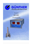
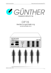
GUNTHER
Hot Runner Systems
Control Unit
DPK2
User Manual
GÜNTHER
Heisskanaltechnik
OP1
OP2
F
1
0
REK2
Poduction Index A, 01. 98
D P K2 _ E 0 1 . D O C
Gu n t h e r H o t R u n n e r S ys t e m s
U s e r M a n u a l C o n t r o l U n i t D P K2
GUNTHER Hot Runner Control Unit DPK2
1. Safety Information
The DPK2 is built and tested according to safety standards declared by the European Council
of Assimilation of Legal Regulations (cf. Appendix B) and has left the factory in perfect
condition. In order to maintain this condition and for safe operation, please read this User
Manual carefully and follow the instructions.
Ensure that your local supply voltage corresponds to the unit´s nominal voltage before you
switch on. For safe operation, the unit must be plugged into an earthed socket. Any
disconnection of the earthed conductor, e.g. by using an extension flex without earthed
conductor, may cause severe danger!
Caution:
Always disconnect the unit before opening! Pull mains plug!
This control unit contains hazardous voltage. Any repair and service work must be carried out
by qualified and authorized personnel only. The components inside the unit are maintenancefree for our customers. They are exclusively serviced by Gunther Hot Runner Systems.
For operation of the control unit, a protected socket must be used. The DPK2 is equipped with
a 16A-shock-proof-plug. Please ensure that the sockets used are protected sufficiently.
Note:
Refer to the chapter on installation and start-up for further instructions on the connection of
the potential-free fault output. Always unplug the unit before touching the components inside!
(Pull mains plug!)
2. Operation
The 2-zone control unit DPK2 is designed for temperture regulation of two hot runner
nozzles. It may be applied for the control of any 230V-load circuit and 5V and 24V low
voltage nozzles of hot runner systems from GUNTHER. The first regulation zone 1 is a
combinatorial one. You can control either low voltage nozzles or 230V-load circuits with this
channel.
!! ATTENTION !!
connect on zone 1 at one time only one nozzle
The second regulation zone 2 can be used to control 230V-loads with a maximum load current
of 10A ( 2300 W ). The DPK2 shown in fig. 2.1 is equipped with one regulators type REK2.
This is connected to the unit front and can be switched on and off with the red key ”1/0”.
© C o p yr i g h t D A V ID S M E Y E R & P A U L G m b H E l e k t r o n i k
2
Gu n t h e r H o t R u n n e r S ys t e m s
U s e r M a n u a l C o n t r o l U n i t D P K2
GÜNTHER
Heisskanaltechnik
OP1
OP2
F
1
0
REK2
Fig. 2.1 Front View DPK2
The REK2 is easy-to-use: all possible functions of the REK2 can be performed via only three
keys. Refer to the quick reference (Appendix B) for basic instructions on the operation of the
REK2.
Please read the enclosed User Manual of the REK2 for a detailed description of the operation
and the possible adjustments of this controller unit.
3. Connection of Control Circuits
Fig. 3.1 Rear View DPK2 (Connection Plugs)
connector pin
1
output
phase zone 1
2
output
phase zone 2
3
output
neutral
PE
protection
earth
Fig. 3.2 Load Connection of Control Unit DPK2
You can connect the heater circuit of both zones using the rearside 4-pin plug. Due to Fig. 3.2
the 230V output of zone 1 is connected to pin 1. Note that the maximum current on this combi
zone is limited to 4A ( 900 W ). The load fuse for this channel is placed on the regulation unit
REK2.
P r o d u c t i o n In d e x A , D o k u m e n t a t i o n S t a n d 0 1 . 9 8
3
Gu n t h e r H o t R u n n e r S ys t e m s
U s e r M a n u a l C o n t r o l U n i t D P K2
The second channel „zone 2“ is able to control heater circuits up to 2000 W (max. 10A). The
load fuse for this 230V nozzle is the 10AF fuse.
There are some clamp in front of the controller DPK2. The low current clamps (red and black)
are for 24V nozzles. The high current clamps are for 5V nozzles.
!! ATTENTION !!
connect at one time only one nozzle
The two thermocouples for each control circuit must be connected to the two Lemosa sockets.
The upper one is for control circuit zone 1 and the lower one is for zone 2.
3.1 ″Ready for Injection″″-Signal
The hot runner is ready for injection as soon as the control circuit is heated up to the required
operating temperature. The REK2 display indicates ”OK” for each control circuit and the
potential-free relay contact is closed. For analysis of the moulding operation you may connect
the potential-free relay contact to the control system of your machine.
Note: Only use extra-low voltage (max. 125V/1A) according to VDE standards (Germany) on
the rear side OK-plug. The necessary equipment is available at Gunther Hot Runner Systems.
3.2 Temperature Lowering
During any long-term production halt it is advisable to lower the temperature of the zone. It is
not necessary to adjust the temperature for the regulation zone – you can control the
temperature of the zone simultaneously by means of a lowering input. If you close the two
contacts of the lowering input with a switch or a potential-free contact, the set temperatures of
the zone is lowered by a preset value.
For further information on the adjustment of the temperature, please read the REK2 User
Manual.
3.3 Serial Interface
The standard configuration of the DPK2 includes an interface type RS232. This 9-pin plug is
© C o p yr i g h t D A V ID S M E Y E R & P A U L G m b H E l e k t r o n i k
4
Gu n t h e r H o t R u n n e r S ys t e m s
U s e r M a n u a l C o n t r o l U n i t D P K2
positioned on the rear of the unit and allows direct connection of the DPK2 to a personal
computer. The Windows-Software ”DPCONTROL” makes the configuration and
visualization of all system parameters possible. It will be provided by Gunther Hot Runner
Systems as necessary.
The REK2 can be equipped with a potential-free interface module for standard types RS232,
RS485 or TTY-20mA. However, for industrial applications, e.g. communication with
machines type Arburg, Engel, etc., we recommend the use of an electrically isolated interface
module.
P r o d u c t i o n In d e x A , D o k u m e n t a t i o n S t a n d 0 1 . 9 8
5
Gu n t h e r H o t R u n n e r S ys t e m s
U s e r M a n u a l C o n t r o l U n i t D P K2
4. Installation and Start-up
a) Installation
• Please position the unit where not heat accumulation will occur.
• The load fuse may not exceed 10A.
• Ensure that the sockets are sufficiently protected for connecting 16A
b) Start-up
• To connect the heating circuit and thermocouples, plug in load connectors.
• Plug in mains plug for power supply.
• Press master key.
• Switch on each REK2 by pressing the red key(s) ”1/0”.
• Set the desired set temperatures of all zones.
• During initial start-up you should activate each control point separately so that possible
faulty connection of either load or thermoelectric couple may be detected.
• After switching on the control unit, please wait for a few minutes until the tool is
heated up evenly.
5. Table of Faults and Defects
During the course of the operation, the REK2 is continually checking the control circuit for
faults and defects. Any fault/defect detected is indicated on the display.
A Fault report
”no sensor 1”
Fault/Defect
Thermocouple of
zone 1 or 3 defect
B Fault report
”no sensor 2”
Thermocouple of
zone 2 or 4 defect
C Fault report
”Pol. TH 1”
Polarity error at
thermocouple of
zone 1 or 3
Polarity error at
thermocouple of
zone 1 or 3
Load circuit of
zone 1 or 3
interrupted
D Fault report
”Pol. TH 2”
E Fault report
”no load 1”
F
Fault report
”no load 2”
G Significant fluctuation of temperature
(+/- 100 °C )
H Temperature in-
Load circuit of
zone 2 or 4
interrupted
Possible Cause
Thermocouple is not
connected or
interrupted
Thermocouple is not
connected or
interrupted
Polarity error at the
thermo couple
Countermeasure
Check connection
plug and -cable of
thermoelectric couple
Check connection
plug and –cable of
thermoelectric couple
Correct the polarity
Polarity error at the
thermo couple
Correct the polarity
Fuse blown
Exchange fuse
Load not connected
Check connecting
cable
Fuse blown
Exchange fuse
Load not connected
Check connecting
cable
Thermocouple defect
or load circuit not
earthed
Load circuit
Check earthing of
load circuit
© C o p yr i g h t D A V ID S M E Y E R & P A U L G m b H E l e k t r o n i k
Check assignment of
6
Gu n t h e r H o t R u n n e r S ys t e m s
crease not satisfactory
U s e r M a n u a l C o n t r o l U n i t D P K2
(swapped)
heater circuit to
thermoelectric couple
Caution:
With 230V-runners the heater circuits must be earthed sufficiently. Lack of earthing or
insufficiently earthed tool/heating element may cause severe errors in the temperature
reading.
P r o d u c t i o n In d e x A , D o k u m e n t a t i o n S t a n d 0 1 . 9 8
7
Gu n t h e r H o t R u n n e r S ys t e m s
U s e r M a n u a l C o n t r o l U n i t D P K2
6. Specifications
Nominal Voltage:
220 to 240V AC, 50/60Hz
Nominal Capacity :
3000 W, 1 x 230V/10A, 1x 230V/4A
Stand-by Capacity :
approx. 10 VA
Load Connection zone 1:
- heater circuit 230V / 4A, harting connector series HAN 3A
- 24V heater circuit 10V / 25A, low current clamp 4mm
- 5V heater circuit 3,7V / 125A, high current clamp
Load Connection zone 2:
heater circuit 230V / 10A, harting connector series HAN 3A
Mains Plug :
3m, 16A-shock-proof-plug
Thermocouple Connection: Thermoelectric couple type L (FeCuNi),
lemosa
OK Output:
Potential-free closing contact (max. 125V/1A not secured by
fuse)
Lowering Input:
Connect a potential-free contact normally open
Fuses:
zone 2 : FF 10A type Schurter Typ SA; superfast for Triacs
Zone 1: F 6,3A
Serial Interface:
Standard: RS232; optional: electrically isolated TTY, RS422,
RS485
Regulation:
″Pulsgruppensteuerung″ (Switching Power Control) for 230V
Phaseangle for low voltage load
Storage Temperature:
up to 70°C
Operating Temperature:
up to 35°C
Protection Type:
IP 20
Dimensions (W, H, D):
150mm x 150mm x 330mm
Colour:
grey and blue (RAL 9018 und RAL 5015)
7. Appendices
© C o p yr i g h t D A V ID S M E Y E R & P A U L G m b H E l e k t r o n i k
8
Gu n t h e r H o t R u n n e r S ys t e m s
U s e r M a n u a l C o n t r o l U n i t D P K2
- Appendix A
Quick Reference REK2
- Appendix B
Declaration of Conformity
Appendix A
P r o d u c t i o n In d e x A , D o k u m e n t a t i o n S t a n d 0 1 . 9 8
9
Gu n t h e r H o t R u n n e r S ys t e m s
U s e r M a n u a l C o n t r o l U n i t D P K2
Quick Reference REK2
GÜNTHER
Heisskanaltechnik
OP1
OP2
F
1
0
REK2
Fig. A.1
Operation Control Panel
The REK2 will be switched on by pressing the key ”1/0” (”ON/OFF”). By pressing the key
1/0 (”ON/OFF”) again, the unit is switched off. This key has no further functions.
KEY
N
A
B
F
A&B
Operation
Mode
count-down of
set value
count-up of
set value
Enter parameter
Menue
Switching
between zone
displays
Parameter Menuel
Key held down
during switch-on
parameter number
count-down
parameter number
count-up
chose next menue
item
A&B
&F
Load default values
(standard
configuration offfactory)
Fig. A.2 Keys: Brief Operating Instructions
© C o p yr i g h t D A V ID S M E Y E R & P A U L G m b H E l e k t r o n i k
10
Gu n t h e r H o t R u n n e r S ys t e m s
U s e r M a n u a l C o n t r o l U n i t D P K2
Appendix B: EG – Declaration of Conformity
For the following below listed products:
Günther-Hot Runner Controller DPK2
we hereby confirm, that above listed products comply to all important (*) safety
requirements that have been declared by the Council of Assimilation of Legal
Regulations by the EC membership countries concerning electromagnetical conformity
(89/336/EWG).
To verify these products to electromagnetical conformity the following standards were
referred to:
EN 50081, Part 2
EN 50082, Part 2
The above mentioned products also comply to:
DIN EN 61010, Teil 1/03.94.
This declaration applies to all above listed products with the folowing production index:
Production Index A
The production index is the number behind the serial number on the identification label
of the product. The identification label is located on the right side of the product.
DAVIDSMEYER & PAUL GmbH Elektronik
Humboldtstr.2-4
D-50181 Bedburg
Bedburg, 19.11.1997
J. Marquardt
(Managing Director)
(*) Expressions recommended by "EMV-Rechtsvorschriften und ihre Anwendung in der Praxis", Franzis-Verlag, 1993
P r o d u c t i o n In d e x A , D o k u m e n t a t i o n S t a n d 0 1 . 9 8
11