1
SMCS116SpW
User Manual
Astrium GmbH
Doc No: SMCS_ASTD_UM_116
Rev.:
1.2
Date:
16.06.2008
Page:
2 of 157
Document Revision History
Revision
Date
Responsible
Modifications
1.0
July 2007
P. Rastetter
First release
1.1
October
2007
U. Liebstückel
Update in chapter 8.6: time code
control register TIME_CNTRL
Chapter 12.14 and 12.15
Add new timing figures for FIFO
interface passive write and FIFO
interface passive read.
1.2
June 2008
U. Liebstückel
Chapter 5.2.1
Replace “Protocol Select Register”
by “Protocol Control Register”
Chapter 7.1.4
Replace “Header x register” by
“Packet Header x register”
Chapter 7.1.6
Replace “ADC_PSIZE” by
“ADC_TEST”
Chapter 8.2.3:
Table: change description of D1 in
register ISR_1
Add description of D1 in register
ISR_1.
Update description of D2 in
register ISR_1
Chapter 8.6:
add description for bit D3 & D4
Chapter 9.1.4:
Add note to the HDRCTRL register
description.
Add bit D1 in register description
of CHKEN
Chapter 9.1.5:
– All Rights Reserved – Copyright per DIN 34 –
SMCS116SpW
User Manual
Revision
Date
Responsible
Astrium GmbH
Doc No: SMCS_ASTD_UM_116
Rev.:
1.2
Date:
16.06.2008
Page:
3 of 157
Modifications
Add additional information about
the checksum generation.
Chapter 9.4.7:
Add a note.
Chapter 9.6.2:
Update of the signal table.
Chapter 9.8.2:
Add note for the use of the RTS
singal.
Chapter 9.8.4:
Add additional information for the
3.3 volt mode.
Chapter 9.9.2:
Add additional information for the
3.3 volt mode.
Chapter 12.8
Add new timing figures for RAM
interface read in 16 bit mode.
Contributions from:
Lars Stopfkuchen
Mohsin Syed
Isaac Tejerina
All Rights Reserved – Copyright per DIN 34: Copying of this document, and giving
it to others and the use or communication of the contents thereof, are forbidden without
express authority. Offenders are liable to the payment of damages. All rights are
reserved in the event of the grant of a patent or the registration of a utility model or
design.
Proprietary Notice: This document is the property of Astrium GmbH and contains
material proprietary to Astrium GmbH. The contents are for confidential use only and
are not to be disclosed to any others in any manner, in whole or in part, except with the
express written approval of Astrium GmbH or to the provision of the relevant contract.
– All Rights Reserved – Copyright per DIN 34 –
SMCS116SpW
User Manual
Astrium GmbH
Doc No: SMCS_ASTD_UM_116
Rev.:
1.2
Date:
16.06.2008
Page:
4 of 157
Table of Contents
1
Introduction..................................................................................................................8
1.1
Scope and Objectives ..............................................................................................8
1.2
List of applicable documents....................................................................................9
1.3
List of Abbreviations...............................................................................................10
2
The need for SMCS116SpW ......................................................................................12
3
SMCS116SpW Features.............................................................................................12
4
The SpaceWire link and protocols ...........................................................................16
5
4.1
Data/Strobe links....................................................................................................16
4.2
Character level flow control....................................................................................18
4.3
Link speeds............................................................................................................18
4.4
Errors on links ........................................................................................................19
The SMCS116SpW Protocols....................................................................................20
5.1 Programming the SMCS116SpW ..........................................................................20
5.1.1 Read internal SMCS116SpW registers............................................................22
5.1.2 Write to internal SMCS116SpW registers ........................................................22
5.1.3 Write to SMCS116SpW ports...........................................................................22
5.1.4 Data read from SMCS116SpW ports ...............................................................22
5.2 Programming the SMCS116SpW with STUP ........................................................23
5.2.1 Switching between STUP Mode and ‘old’ SMCS116 protocol mode ...............23
5.2.2 Write internal SMCS116SpW registers ............................................................24
5.2.3 Read internal SMCS116SpW registers............................................................26
5.2.4 Return Address ................................................................................................27
5.2.5 Protocol error interrupts ...................................................................................28
6
SMCS116SpW Applications ......................................................................................29
7
Register Set................................................................................................................32
7.1 Register Address Map ...........................................................................................32
7.1.1 General Control Registers ...............................................................................32
7.1.2 Clock Control Registers ...................................................................................32
7.1.3 SpaceWire Link Registers................................................................................33
7.1.4 Packet Header Registers .................................................................................33
7.1.5 FIFO Interface Registers..................................................................................34
7.1.6 ADC Interface Registers ..................................................................................34
7.1.7 DAC Interface Registers ..................................................................................35
7.1.8 RAM Interface Registers..................................................................................35
7.1.9 Timer1 Registers..............................................................................................37
7.1.10 Timer2 Registers...........................................................................................37
7.1.11 Host FIFO Interface Registers ......................................................................38
7.1.12 UART1 Registers ..........................................................................................38
7.1.13 Interrupt Mask Registers ...............................................................................39
– All Rights Reserved – Copyright per DIN 34 –
SMCS116SpW
User Manual
7.1.14
7.1.15
7.1.16
7.1.17
7.1.18
7.1.19
7.1.20
8
Astrium GmbH
Doc No: SMCS_ASTD_UM_116
Rev.:
1.2
Date:
16.06.2008
Page:
5 of 157
Interrupt Status Registers .............................................................................39
GPIO Registers.............................................................................................39
UART2 Registers ..........................................................................................40
SpaceWire TIMECODE Registers ................................................................40
STUP Registers ............................................................................................41
Semaphore Control Register.........................................................................41
Reset Registers ............................................................................................41
General Registers ......................................................................................................42
8.1
Interface enable .....................................................................................................42
8.2 Interrupts................................................................................................................43
8.2.1 Interrupt Signal.................................................................................................43
8.2.2 Interrupt Masking .............................................................................................43
8.2.3 Interrupt Status Registers ................................................................................43
8.3 Resets....................................................................................................................48
8.3.1 Reset Registers ...............................................................................................48
9
8.4
Semaphore ............................................................................................................48
8.5
STUP Registers .....................................................................................................49
8.6
Time interface registers .........................................................................................51
SMCS116SpW Modules and Interfaces....................................................................53
9.1 Link interface .........................................................................................................53
9.1.1 Link interface signals .......................................................................................53
9.1.2 SpaceWire Link Registers................................................................................53
9.1.3 SpaceWire Link Speed Register ......................................................................55
9.1.4 Packet Header Registers .................................................................................57
9.1.5 Packet Header, Checksum Generation and Wormhole Routing ......................58
9.2 Host interface.........................................................................................................60
9.2.1 HOST interface signals ....................................................................................60
9.3 Host FIFO ..............................................................................................................61
9.3.1 Transmit / receive host data over / from the SpaceWire link ............................62
9.4 RAM interface ........................................................................................................63
9.4.1 RAM Interface enable ......................................................................................63
9.4.2 RAM interface signals ......................................................................................63
9.4.3 External status signals .....................................................................................64
9.4.4 External control signals ....................................................................................64
9.4.5 RAM I/F Control Register .................................................................................65
9.4.6 Transmit data over SpaceWire link ..................................................................65
9.4.7 Receive data over SpaceWire link ...................................................................67
9.4.8 Bank select ......................................................................................................68
9.4.9 RAM I/F wait states..........................................................................................69
9.4.10 SMCS116SpW protocol RAM interface port .................................................69
9.4.11 RAM I/F access.............................................................................................70
9.5 FIFO interface ........................................................................................................74
9.5.1 FIFO Interface enable ......................................................................................74
– All Rights Reserved – Copyright per DIN 34 –
SMCS116SpW
User Manual
9.5.2
9.5.3
Astrium GmbH
Doc No: SMCS_ASTD_UM_116
Rev.:
1.2
Date:
16.06.2008
Page:
6 of 157
FIFO interface registers ...................................................................................74
FIFO interface signals......................................................................................78
9.6 ADC Interface ........................................................................................................84
9.6.1 ADC interface enable.......................................................................................84
9.6.2 ADC interface signals ......................................................................................84
9.6.3 ADC interface control registers ........................................................................85
9.6.4 Packet composition and forming ......................................................................87
9.6.5 ADC timing requirements .................................................................................88
9.6.6 Sequence for Analogue-Digital Conversion .....................................................88
9.7 DAC Interface ........................................................................................................91
9.7.1 DAC interface enable.......................................................................................91
9.7.2 DAC interface signals ......................................................................................91
9.7.3 DAC Interface Control Registers......................................................................92
9.7.4 DAC Timing Requirements ..............................................................................92
9.7.5 Sequence for Digital-Analogue conversion ......................................................93
9.8 UART Interface ......................................................................................................94
9.8.1 UART Signals ..................................................................................................94
9.8.2 UART1 Registers .............................................................................................94
9.8.3 UART2 Registers .............................................................................................96
9.8.4 UART Baud Rate .............................................................................................96
9.8.5 UART Configuration.........................................................................................97
9.8.6 UART Protocol .................................................................................................98
9.8.7 UART SpaceWire packet .................................................................................98
9.9 Timers....................................................................................................................99
9.9.1 Timer Signals ...................................................................................................99
9.9.2 Timer Registers................................................................................................99
9.9.3 Timer Configuration .......................................................................................101
9.9.4 Timer Operation .............................................................................................101
9.10
GPIO Interface ..................................................................................................103
9.11
JTAG Interface..................................................................................................104
10 Signal Description ...................................................................................................105
10.1
IOB control bus .................................................................................................109
10.2
GPIO Signals ....................................................................................................110
11 Electrical Specifications..........................................................................................111
11.1
PLL-Filter ..........................................................................................................113
11.2
3.3 Volt/5 Volt Operating Voltage......................................................................113
11.3
Power and Ground Guidelines ..........................................................................114
12 Timing Parameters...................................................................................................115
12.1
Clock.................................................................................................................115
12.2
Reset ................................................................................................................116
12.3
Host write address ............................................................................................117
– All Rights Reserved – Copyright per DIN 34 –
SMCS116SpW
User Manual
Astrium GmbH
Doc No: SMCS_ASTD_UM_116
Rev.:
1.2
Date:
16.06.2008
Page:
7 of 157
12.4
Host write data ..................................................................................................118
12.5
Host read address.............................................................................................119
12.6
Host read data ..................................................................................................120
12.7
RAM interface write...........................................................................................121
12.8
RAM interface read ...........................................................................................122
12.9
RAM interface external bus request..................................................................124
12.10
RAM interface external control read...............................................................125
12.11
RAM interface external control write ..............................................................126
12.12
FIFO interface write .......................................................................................127
12.13
FIFO interface read........................................................................................128
12.14
FIFO interface passive write ..........................................................................129
12.15
FIFO interface passive read...........................................................................130
12.16
ADC interface.................................................................................................131
12.17
DAC interface.................................................................................................132
12.18
Timer..............................................................................................................133
12.19
External Interrupt ...........................................................................................134
12.20
Links ..............................................................................................................135
12.21
Test Port (JTAG)............................................................................................136
12.21.1
Test Port Reset ........................................................................................137
13 Mechanical Data.......................................................................................................138
13.1
Package Dimensions ........................................................................................138
13.2
Pin Assignment .................................................................................................140
14 Additional Information.............................................................................................142
14.1
BSDL File for the SMCS116SpW......................................................................142
15 Differences between the SMCS116SpW and the old SMCS116 ...........................152
15.1
Pin Modifications...............................................................................................152
15.2
Signal Modifications ..........................................................................................152
15.3 Summary of changed/modified/added registers................................................153
15.3.1 FIFO interface register modifications ..........................................................156
– All Rights Reserved – Copyright per DIN 34 –
SMCS116SpW
User Manual
Astrium GmbH
Doc No: SMCS_ASTD_UM_116
Rev.:
1.2
Date:
16.06.2008
Page:
8 of 157
1 Introduction
Advanced sensor interfaces such as CCD cameras, spectrometers etc. introduce ever
increasing data rates between the sensor front-end and the signal processing unit. Often
interfaces have to be designed specifically, causing high development costs and long
development times. The higher data rates involved in modern sensor types additionally
introduce design issues such as noise, fault tolerance, command and data handling,
limited pin count and power consumption issues. A communication controller using the
SpaceWire standard was identified as an important element and implemented in the
SMCS, providing the communication interfaces in a network of multiple processing
elements. Since SpaceWire has been introduced for inter-processor communication, the
logical consequence was to use SpaceWire for connecting sensor interfaces as well.
The SMCS116SpW is using a simple protocol (protocol of SMCS116) or the STUP for
efficient packet oriented data transfer. The SMCS116SpW is implemented in the
radiation-tolerant technology (MG2RT) from Atmel.
The SMCS116SpW can be operated in a 5 V or in a 3,3 V environment.
1.1 Scope and Objectives
This document describes in detail the SMCS116SpW chip. The SMCS116SpW provides
an interface between a SpaceWire link according to the SpaceWire Standard ECSS-E-5012A and several different interfaces:
1. Host interface
2. FIFO interface
3. ADC interface
4. DAC interface
5. RAM interface
6. UART interface
7. JTAG (IEEE 1149.1)
8. General purpose I/O
9. Timer / Event Counter
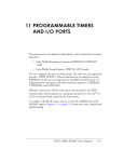
A top level block diagram of the SMC116SpW is given in the figure below.
– All Rights Reserved – Copyright per DIN 34 –
Astrium GmbH
Doc No: SMCS_ASTD_UM_116
Rev.:
1.2
Date:
16.06.2008
Page:
9 of 157
SMCS116SpW
User Manual
Figure 1: SMCS116SpW Block Diagram
1.2 List of applicable documents
AD
Title
Doc. No.
AD1
SpaceWire -Links, nodes, routers
and network, 24 January 2003.
ECSS-E-50-12A
AD2
SMCS116SpW Requirements
Specification
SMCS116SpW_RS01
AD3
SMCSlite User Manual,
09.03.2001
DIPSAPII-DAS-3107, Issue 1.1
– All Rights Reserved – Copyright per DIN 34 –
SMCS116SpW
User Manual
Astrium GmbH
Doc No: SMCS_ASTD_UM_116
Rev.:
1.2
Date:
16.06.2008
Page:
10 of 157
1.3 List of Abbreviations
Acronym
Description
AD
Applicable Document
ASIC
Application Specific Integrated Circuit
BSDL
Boundary Scan Description Language
CPU
Central Processing Unit
DPRAM
Dual-Port RAM
EEP
Error End Of Packet
EOP
End Of Packet
ESC
Escape
FCT
Flow Control Token
FIFO
First In First Out
FPGA
Field Programmable Gate Array
GPIO
General Purpose Input Output
HOCI
Host Control Interface
HW
Hardware
JTAG
Joint Testing Action Group
LSB
Least Significant Bit
LVDS
Low Voltage Differential Signalling
MSB
Most Significant Bit
PLL
Phase Locked Loop
SMCS
Scalable Multichannel Communication Subsystem
SpW
SpaceWire
SRAM
Static Random Access Memory
– All Rights Reserved – Copyright per DIN 34 –
SMCS116SpW
User Manual
Astrium GmbH
Doc No: SMCS_ASTD_UM_116
Rev.:
1.2
Date:
16.06.2008
Page:
11 of 157
STUP
Serial Transfer Universal Protocol
UART
Universal Asynchronous Receiver Transmitter
– All Rights Reserved – Copyright per DIN 34 –
SMCS116SpW
User Manual
Astrium GmbH
Doc No: SMCS_ASTD_UM_116
Rev.:
1.2
Date:
16.06.2008
Page:
12 of 157
2 The need for SMCS116SpW
Connecting a non-intelligent node to a processing element requires not only the
communication controller, but usually a controlling instance for the communication
circuitry. The latter has to be configured for settings like bit rate, packet sizes, handshake
protocols etc. Should the non-intelligent node require remote control via commands,
usually a second link, dedicated for commands is introduced. Using a SpaceWire link for
that purpose eliminates the need for separate data and control paths, since the
communication controller can differentiate between the two entities. In addition, it can be
remotely configured, can execute simple commands and provides special I/O pins to
control the interface unit.
Nevertheless, the SMCS332SpW with its three links may be over dimensioned for some
applications, or a special controlling instance such as an FPGA is still required on the
interface node to e.g. control Analogue-to-Digital converters etc.
Thus the need for a smaller (with one link only) SMCS with more system support for nonintelligent nodes was identified, and the SMCS116SpW introduced. Target requirements
for the design were:
•
small package (100 pins)
•
low power consumption
•
provide sufficient control lines to configure and operate I/O devices
•
provide a configurable memory interface to address standard SRAM memory (e.g.
for data buffers) and FIFOs.
•
provide additional system support, such as timers etc.
•
be manufactured in a radiation-tolerant technology.
3 SMCS116SpW Features
The SMCS116SpW provides one SpaceWire serial communication link with 2,5 to 200
Mbit/s data transmit rate. It features a link disconnect detection and parity check at
character level as well as an additional checksum generation/check at packet level.
Besides the serial SpaceWire link, the SMCS116SpW provides several different interface
types:
•
Host interface
•
FIFO interface
•
ADC interface
•
DAC interface
•
RAM interface
•
UART interface
– All Rights Reserved – Copyright per DIN 34 –
SMCS116SpW
User Manual
•
JTAG (IEEE 1149.1)
•
General purpose I/O
•
Timer / Event Counter
Astrium GmbH
Doc No: SMCS_ASTD_UM_116
Rev.:
1.2
Date:
16.06.2008
Page:
13 of 157
FIFO interface
The FIFO interface provides the control signals full, write, empty and read, depending on
the direction of the data flow (receive/transmit).
Data received from the FIFO interface is sent over the SpaceWire link grouped in packets.
The length of a packet (in bytes) can be specified either by setting an internal counter or
by external signals. This interface can be programmed to use 0 to 7 wait states.
ADC/DAC interface
The ADC interface allows connecting an ADC with a width of up to 16 bits directly to the
SMCS116SpW. The AD conversion can be started by request via link or in a cyclic manner
triggered by the on-chip timers. When the AD conversion is ready, this is recognized by an
external signal like "ready" or by an internal trigger, for example from the on-chip timer.
After reading the sample from the ADC it is then sent over the link. An 8-bit address
generator is provided to allow multiplexing of analog signals. The address generator will
start at a pre-programmed start address and will be incremented after each conversion.
The DAC interface is very similar to the ADC interface. It provides up to 16 data lines and
the required control signals. The data to be sent to the DAC is received from the link and is
stored in a register until the command "start DAC" is received. After that command the
register values will be put to the DAC.
Memory Interface
The RAM interface provides a 16-bit data bus and 16-bit address bus. Four chip select
lines allow addressing four different memory partitions (banks). This partitioning into
different banks is done using 4 internal address boundary registers. These are 8 bit wide
and provide a minimum page size of 1024 words. The memory interface can be
programmed to use 0 to 7 wait states.
GPIO Interface
The general purpose I/O (GPIO Interface) provides up to 24 bidirectional signal lines. The
direction (input or output) of each GPIO line can be set individually via register. Data
to/from the GPIO lines is written / read via the GPIO data register. The GPIO provides 8
dedicated I/O lines, the remaining 16 lines of the port are shared with the ADC address
and host data bus. These GPIO lines are available when the corresponding unit (e.g. the
host data bus) of the SMCS116SpW is not being used (disabled).
UART interface
– All Rights Reserved – Copyright per DIN 34 –
Astrium GmbH
Doc No: SMCS_ASTD_UM_116
Rev.:
1.2
Date:
16.06.2008
Page:
14 of 157
SMCS116SpW
User Manual
Two independent UARTs are included in the SMCS116SpW as well. One UART uses
dedicated I/O lines whereas the second UART is sharing its pins with the GPIO port. The
transmit rate of the UARTs in bps can be programmed via a 12-bit wide register with a
maximum bit rate of about 780 kbit/s. The UARTs can optionally use hardware handshake
(rts/cts).
Host Interface
Although the SMCS116SpW is primarily designed to be remotely controlled, it can
nevertheless be programmed and controlled by a local host if required. For that purpose a
host interface provides 8 multiplexed data and address lines.
Timers / Event Counter
Two 32-bit on-chip timers are available on the SMCS116SpW. Each timer provides a 32
bit counter and a 32 bit reload register. The two timers can be operated independently or
cascaded. The timers can also be used to set an external signal when the timeout value is
reached.
Configuration
After a chip reset the SMCS116SpW is configured by the internal controller. This can be
either by receiving the configuration data from the SpaceWire link or by an external
controller connected to the host port of the SMCS116SpW.
Shared I/O
Some of the functions of the SMCS116SpW presented above share the same I/O pins.
This means, that some functions are mutually exclusive. As an example, the GPIO port
shares some of its I/O pins with the host interface. If the host interface is not used, these
pins are available for GPIO; otherwise they are used as the host address and data bus.
The selection of which functions are being used is made by programming the appropriate
registers after a chip reset. A short overview of the pin allocation and combinations of
functions is given in the table below:
Interface
Type
Example Mode
1
2
3
Host / GPIO2
Timer1
Timer2
UART1
– All Rights Reserved – Copyright per DIN 34 –
Astrium GmbH
Doc No: SMCS_ASTD_UM_116
Rev.:
1.2
Date:
16.06.2008
Page:
15 of 157
SMCS116SpW
User Manual
Interface
Type
Example Mode
1
2
3
UART2
GPIO0
GPIO7-0
GPIO1
IOB7-0
FIFO
active mode
RAM
-
-
GPIO7-0
IOB7-0
-
passive mode
-
ADC
-
-
DAC
-
-
Note that if the passive FIFO mode is used on the SMCS116SpW, the ADC and DAC
interfaces can then not be used.
JTAG interface
For testing purposes a standard IEEE 1149.1 interface is provided. It supports the JTAG
functions Bypass, Extest, Sample/Preload, All-Tristate and IDCode.
– All Rights Reserved – Copyright per DIN 34 –
SMCS116SpW
User Manual
Astrium GmbH
Doc No: SMCS_ASTD_UM_116
Rev.:
1.2
Date:
16.06.2008
Page:
16 of 157
4 The SpaceWire link and protocols
The SpaceWire DS-Link standard defines a full duplex bit serial point to point link with a
raw transmit rate of up to 400 Mbit/sec. The link consists of 2 signals in each direction, one
for strobe and one for data. By coding the strobe that it only changes level when the data
does not, clock recovery and data synchronisation can be achieved by XOR-ing of data
and strobe signals without having the need to run the strobe at very high frequencies. The
exchange layer of the protocol is used to implement flow control which avoids overflow of
the front end buffers. Error detection is provided by implemented parity checks during
transmission and by timeout supervision in case of inter-connect failures.
The SpaceWire standard aims only to define a transport medium between two nodes and
covers the protocol layers only up to the packetization layer. This has two consequences:
1. packetization with address headers allow to use this link standard in networks using
routers,
2. since the standard does not define the data payload within the packets, an efficient
transaction layer definition is missing.
To compensate for these deficiencies of the SpaceWire specification, the SMCS116SpW
implementation introduces an (optional) transaction layer extension to the SpaceWire
protocol standard. This high level protocol extension supports applications in fault tolerant
systems, heterogeneous architectures, feature power saving modes and remote
configuration of the communication controller and autonomous command execution. With
this flexible and powerful protocol, the SpaceWire link has many advantages over
commonly used interface solutions such as RS-485 etc.
4.1 Data/Strobe links
The SpaceWire links use a protocol with two wires in each direction, one for data and one
to carry a strobe signal and are also referred to as data/strobe (DS-Links). Each DS pair
carries characters and an encoded clock. The characters can be data or control
characters. The figure below shows the format of data and control characters on the data
and strobe wires. Data characters are 10 bits long and consist of a parity bit, a flag which
is set to 0 to indicate a data character, and 8 bits of data. Control characters are 4 bits long
and consist of a parity bit, a flag which is set to 1 to indicate a control character, and 2 bits
to indicate the type of control character.
The DS-Link protocol ensures that only one of the two wires of the data strobe pair has an
edge in each bit time. The levels on the data wire give the data bits transmitted. The strobe
signal changes whenever the data signal does not. These two signals encode a clock
together with the data bits, permitting asynchronous detection of the data at the receiving
end. The data and control characters are of different lengths, for this reason the parity bit
in any character covers the parity of the data or control bits in the previous character, and
the data/control flag in the same character, as shown in the above figure. This allows
single bit errors in the character type flag to be detected. Odd parity checking is used.
Thus the parity bit is set/unset to ensure that the bits covered, inclusive of the parity bit
– All Rights Reserved – Copyright per DIN 34 –
Astrium GmbH
Doc No: SMCS_ASTD_UM_116
Rev.:
1.2
Date:
16.06.2008
Page:
17 of 157
SMCS116SpW
User Manual
(see following figure), always contain an odd number of 1’s. The coding of the characters
is shown in the table below. To ensure the immediate detection of parity errors and to
enable link disconnection to be detected NULL characters are sent in the absence of other
characters.
Character Type
Abbreviation
Data Character
Coding
P0DDDDDDDD
Control characters:
Flow Control
FCT
P100
Normal End of Packet
EOP
P101
Error End of Packet
EEP
P110
Escape
ESC
P111
NULL
ESC + FCT
Control codes:
Null
P1110100
Time Code
ESC + DATA
P11110DDDDDDDD
P = Parity bit
D = Data bit
– All Rights Reserved – Copyright per DIN 34 –
SMCS116SpW
User Manual
Astrium GmbH
Doc No: SMCS_ASTD_UM_116
Rev.:
1.2
Date:
16.06.2008
Page:
18 of 157
4.2 Character level flow control
Character level flow control is performed in each DS-Link module, and the additional flow
control characters used are not visible to the higher-level packet protocol. The character
level flow control mechanism prevents a sender from overrunning the input buffer of a
receiving link. Each receiving link input contains a buffer for at least 8 characters (16
characters of buffering is in fact provided). Normal-characters are data character and
EOP/EEP. Whenever the link input has sufficient buffering available to consume a further
8 normal characters a FCT is transmitted on the associated link output, and this FCT gives
the sender permission to transmit a further 8 normal characters. Once the sender has
transmitted a further 8 normal characters it waits until it receives another FCT before
transmitting any more characters. The provision of more than 8 normal characters of
buffering on each link input ensures that in practice the next FCT is received before the
previous block of 8 normal characters has been fully transmitted, so the character-level
flow control does not restrict the maximum bandwidth of the link.
4.3 Link speeds
The SpaceWire links can support a range of communication speeds, which are
programmed by writing to registers. At reset all links are configured to run at the base
speed of 10 Mbits/sec. Only the transmission speed of a link is programmed as reception
is asynchronous. This means that links running at different speeds can be connected,
provided that each device is capable of receiving at the speed of the connected
transmitter. The transmission speeds of the SpaceWire link of the SMCS116SpW is
programmed by the register BITRATE (0x02). Possible link speeds are:
The maximum receive bit rate is 200 MBit/s at 5 Volt and 100 MBit/s at 3.3 Volt.
– All Rights Reserved – Copyright per DIN 34 –
Astrium GmbH
Doc No: SMCS_ASTD_UM_116
Rev.:
1.2
Date:
16.06.2008
Page:
19 of 157
SMCS116SpW
User Manual
BITRATE Register
(D3-D0)
Link Speed @ 5 V
[Mbit/s]
Link Speed @ 3,3 V
[Mbit/s]
“0000"
2.5
2.5
“0001"
5
5
“0010"
10 (default)
10 (default)
“0011"
20
25
“0100"
25
50
“0101"
33
100
“0110"
50
100
“0111"
100
100
“1000"
150
100
“1001"
200
100
"1010" to "1111"
reserved
reserved
4.4 Errors on links
Link inputs can detect parity and disconnection conditions as errors. A single bit odd parity
system will detect single bit errors at the link character level. The protocol to transmit
NULL characters in the absence of other characters enables disconnection of a link to be
detected. A disconnection error indicates that:
1. the link has been physically disconnected;
2. an error has occurred on the link or at the other end of the link, which may have
then stopped transmitting.
The status bits in the STATUS register flag a parity and/or disconnection error that has
occurred on the link. A parity and a disconnect error can be detected independently. When
a SpW link detects a parity error on its input it halts its output. This is detected as a
disconnect error at the other end of the link, causing this to halt its output also. Detection
of an error causes the link to be stopped. Thus, the disconnect behaviour ensures that
both ends are stopped. Each end can then be restarted.
– All Rights Reserved – Copyright per DIN 34 –
SMCS116SpW
User Manual
Astrium GmbH
Doc No: SMCS_ASTD_UM_116
Rev.:
1.2
Date:
16.06.2008
Page:
20 of 157
5 The SMCS116SpW Protocols
The SMCS116SpW supports both the standard SpaceWire link protocol (transparent
mode) as well as the header generation required for the enhanced transaction layer of the
SMCS116SpW. This protocol uses specific protocol headers that can be generated by the
SMCS116SpW without requiring an external host controller. These headers are stored in
specific header registers which allows headers with a length of 0 (equalling the transparent
mode) to eight bytes per packet. Packetization of data sent by the SMCS116SpW over the
link is also done automatically according to the settings of a packet length register.
Another feature provided by the transaction layer supported by the SMCS116SpW is an
automatic checksum generation on the link. This is generated and checked automatically
by the SMCS116SpW without requiring support from a host or other external source.
Errors on the link are flagged and a special error packet is sent over the link to signal the
error condition.
Programming the SMCS116SpW internal registers is done via the SpaceWire link. All
internal registers are 8-bit wide addressable. Two simple commands (read and write)
suffice to access all functions and registers of the SMCS116SpW. The interfaces of the
SMCS116SpW such as the FIFO, UART, ADC/DAC and memory interface are accessed
by a simple read or write operation to the corresponding interface address. In the case of
FIFO, Host, UART and memory interface, a packet oriented access is also possible
(meaning transferring multiple bytes with a single command). In case a communication
memory is connected to the SMCS116SpW, this can be read and written to via the link
using the RAM_TST_ADRx / RAM_RST_ADRx and RAM_TED_ADRx / RAM_RED_ADRx
registers.
5.1 Programming the SMCS116SpW
Programming the SMCS116SpW internal registers is done via a simple protocol over the
SpaceWire link or STUP or directly via the host interface. The simple protocol requires a
command byte and, if necessary, one or more data bytes; it ignores following bytes, if
more bytes are sent. The STUP used 4 bytes for commanding and supports also logical
addressing.
All internal registers are 8-bit wide addressable. Two commands (read and write) suffice to
access all registers of the SMCS116SpW.
The SMCS116SpW provides registers and ports; a register contains exactly one byte
(read / write), whereas a port (e.g. a FIFO interface) behaves like a FIFO, meaning that
multiple data bytes can be read or written from/to the port.
– All Rights Reserved – Copyright per DIN 34 –
SMCS116SpW
User Manual
Astrium GmbH
Doc No: SMCS_ASTD_UM_116
Rev.:
1.2
Date:
16.06.2008
Page:
21 of 157
The ports of the SMCS116SpW such as the FIFO, UART, ADC and RAM interface are
accessed by a read/write command to the corresponding port address. In the case of
FIFO, Host, UART and memory interface, a packet oriented access is also possible
(meaning transferring multiple data bytes with a single command). The read/write selection
of a command is done by setting bit7 (MSB) of the first byte to one (read) or zero (write).
– All Rights Reserved – Copyright per DIN 34 –
SMCS116SpW
User Manual
Astrium GmbH
Doc No: SMCS_ASTD_UM_116
Rev.:
1.2
Date:
16.06.2008
Page:
22 of 157
5.1.1 Read internal SMCS116SpW registers
Read Command
Byte 0 defines whether a write (D7 = 0) or a read (D7 = 1) command is performed.
1 & Register
Address (D6:0)
XB (0 or more
bytes)*
EOP
*Note: SMCS116SpW ignores dummy bytes
Read reply packet is sent after a read command.
0 & Register
Address
Register Value
EOP
5.1.2 Write to internal SMCS116SpW registers
0 & Register
Address (D6:0)
New Register
Value
XB (0 or more
bytes)*
EOP
5.1.3 Write to SMCS116SpW ports
0 & Port Address
Data byte0
Data byte1
Data byte1
Data byte
Data byte N-1
Data byte N
EOP
5.1.4 Data read from SMCS116SpW ports
0 & Port Address
Data byte0
Data byte1
Data byte1
Data byte
Data byte N-1
Data byte N
EOP
– All Rights Reserved – Copyright per DIN 34 –
SMCS116SpW
User Manual
Astrium GmbH
Doc No: SMCS_ASTD_UM_116
Rev.:
1.2
Date:
16.06.2008
Page:
23 of 157
5.2 Programming the SMCS116SpW with STUP
The STUP (Serial Transfer Universal Protocol) is implemented to support logical
addressing. The protocol identifier (PID) of STUP is 239 dec. or 0xEF (hex).
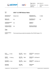
5.2.1 Switching between STUP Mode and ‘old’ SMCS116 protocol mode
The SMCS116SpW will start in the SMCS116 mode after reset and has to be switched to
the STUP Mode if desired. This is necessary to be compliant with existing software that
controls the SMCS116SpW over the SpaceWire.
The SMCS116SpW can be switched into STUP Mode (see figure below) by the following
steps:
1. via SpaceWire:
• first packet should be a READ command to register 0x7C. This READ
command has to be at least 4 or more bytes long with the logical address
0xFE and the protocol identifier 0xEF.
Ö Bit D0 of Protocol Control Register (0x79) is set to ‘1’ automatically.
Read Command
0xFE
0xEF
0 or more bytes
EOP
•
0xXX
0xFC
setting Bit D0 of Protocol Control Register (0x79) to ‘1’ with an write
command.
2. via Host IF:
• setting Bit D0 of Protocol Control Register (0x79) to ‘1’
– All Rights Reserved – Copyright per DIN 34 –
Astrium GmbH
Doc No: SMCS_ASTD_UM_116
Rev.:
1.2
Date:
16.06.2008
Page:
24 of 157
SMCS116SpW
User Manual
SMCS116Spw
RESET
Read command to 0x7C
- 4 Bytes or more
- second byte : Protocol ID
First Spw
Packet
New Protocol
Mode
D0 = ‚1'
Old SMCS116
Mode
Protocol Select
Register
D0 = ?
D0 = ‚0'
5.2.2 Write internal SMCS116SpW registers
Write on SMCS116SpW Register
Logical Address
Protocol ID
Return Address
Command &
Register Address
Data (1 or more
byte *)
Checksum
Checksum
EOP
*Note: SMCS116SpW ignores dummy bytes
Byte 4 defines whether a write (D7 = 0) or a read (D7 = 1) command is performed.
Checksum is appended when checksum generation is enabled.
– All Rights Reserved – Copyright per DIN 34 –
SMCS116SpW
User Manual
Astrium GmbH
Doc No: SMCS_ASTD_UM_116
Rev.:
1.2
Date:
16.06.2008
Page:
25 of 157
Example:
Enable RAM IF
0x7E
0xEF
0x98
EOP
0x7E
0x74
0x01
EOP
0x20
0x00
0x20
0x01
Write on SMCS116SpW Port
Logical Address
Protocol ID
Return Address
Port Address
Data
Data
Data
Data
Data
Data
Data
Data (or more byte)
Checksum
Checksum
EOP
Example:
Write on RAM IF Data PORT
0x7E
0xEF
0x20
0x43
0xAA
0xAA
0xAA
0xAA
0xAA
0xAA
0xAA
EOP
– All Rights Reserved – Copyright per DIN 34 –
SMCS116SpW
User Manual
Astrium GmbH
Doc No: SMCS_ASTD_UM_116
Rev.:
1.2
Date:
16.06.2008
Page:
26 of 157
5.2.3 Read internal SMCS116SpW registers
Read Command
Logical Address
Protocol ID
Return Address
Command &
Register Address
XB (0 or more
bytes)*
Checksum
Checksum
EOP
*Note: SMCS116SpW ignores dummy bytes
Byte 4 defines whether a write (D7 = 0) or a read (D7 = 1) command is performed.
Checksum is interpreted when checksum generation is enabled.
Read Reply
Read reply packet is sent after a read command.
Return Address
Protocol ID
Logical Address
Register Address
Data
Checksum
Checksum
EOP
Checksum is appended when checksum generation is enabled.
Example:
Read IFCONF Register (0x01) Command
0x7E
0xEF
0x20
0x81
EOP
Read IFCONF Register (0x01) Reply Packet
0x20
0xEF
Data
EOP
0x7E
0x01
– All Rights Reserved – Copyright per DIN 34 –
SMCS116SpW
User Manual
Astrium GmbH
Doc No: SMCS_ASTD_UM_116
Rev.:
1.2
Date:
16.06.2008
Page:
27 of 157
Interface data packet/ interrupt packet
An interface data packet or an interrupt packet is sent autonomously because of an
interrupt or a FIFO, RAM, ADC or UART Interface data transmission.
Return Address
OR
Protocol ID
Logical Address
Interrupt Status
Register Address
Alternative Return
Address
Data
Port Address or
Checksum
Checksum
EOP
Checksum is appended when checksum generation is enabled.
Example:
Interrupt Packet
0xAB *
0xEF
0x7E
0x5F
ISR_0
ISR_1
ISR_2
EOP
*Note: Return Address has to be set before.
5.2.4 Return Address
The SMCS116SpW stores the last received return address. This return address is used
for:
•
•
all register read replies
data transmitted from RAM, FIFO, ADC, UART and Interrupt controller if this
is selected in the Return Select Register
An alternative Return Address can be written to the Alternative Return Address Register.
This return address is used only for:
•
data transmitted from RAM, FIFO, ADC, UART and Interrupt controller if this
is selected in the Return Select Register
– All Rights Reserved – Copyright per DIN 34 –
SMCS116SpW
User Manual
Astrium GmbH
Doc No: SMCS_ASTD_UM_116
Rev.:
1.2
Date:
16.06.2008
Page:
28 of 157
5.2.5 Protocol error interrupts
In the case of a protocol error like
- wrong logical address,
- wrong protocol identifier,
- wrong register address (example: read of a data port)
Bit 1 in the interrupt status register (ISR_0) will be set.
In the case of a packet length < 4 byte, bit 2 in the interrupt status register ISR_0 will be
set.
The wrong packet will be ignored by the SMCS116SpW.
– All Rights Reserved – Copyright per DIN 34 –
SMCS116SpW
User Manual
Astrium GmbH
Doc No: SMCS_ASTD_UM_116
Rev.:
1.2
Date:
16.06.2008
Page:
29 of 157
6 SMCS116SpW Applications
The SMCS116SpW is targeted at two main different application areas:
1. Embedded systems
2. Communication device for processor systems
Embedded Systems
The main application targets of the SMCS116SpW are modules and units without any
built-in communication features, such as special image compression chips, application
specific programmable logic or mass memory. The SMCS116SpW is perfectly suited to be
used on "non-intelligent" modules such as A/D converter or sensor interfaces, due to its
"control by link" feature and system control facilities. In addition, its fault tolerance feature
makes the device very interesting for many critical industrial measurement and control
systems.
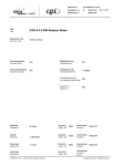
Example applications of the SMCS116SpW as communication and system controller on an
interface node consisting of an ADC and DAC and one where the SMCS116SpW is
connected to four banks of memory are given in the figures below:
– All Rights Reserved – Copyright per DIN 34 –
SMCS116SpW
User Manual
Astrium GmbH
Doc No: SMCS_ASTD_UM_116
Rev.:
1.2
Date:
16.06.2008
Page:
30 of 157
– All Rights Reserved – Copyright per DIN 34 –
SMCS116SpW
User Manual
Astrium GmbH
Doc No: SMCS_ASTD_UM_116
Rev.:
1.2
Date:
16.06.2008
Page:
31 of 157
Communication device for microprocessors
Many applications require a link front end providing one link, but no controller instance on
that unit. Due to the communication memory interface of the SMCS116SpW, it is also
satisfying the requirements of these applications. Due to its small package and low power
consumption it is an excellent alternative to FPGA based solutions. A system using the
SMCS116SpW as a communication front-end for a microcontroller is shown in the
following figure:
– All Rights Reserved – Copyright per DIN 34 –
SMCS116SpW
User Manual
Astrium GmbH
Doc No: SMCS_ASTD_UM_116
Rev.:
1.2
Date:
16.06.2008
Page:
32 of 157
7 Register Set
This chapter describes the SMCS116SpW registers.
General Conventions:
bit 0 (D0) = least significant bit,
bit 7 (D7) = most significant bit,
D x:0 means data bit x until bit 0.
7.1 Register Address Map
The tables in the sections below give a reference description of the SMCS116SpW. All
registers are 8 bits wide; all registers contain the value 0x00 after reset except where
stated differently. Register addresses given are in hexadecimal notation.
7.1.1 General Control Registers
Address
Register
Description
r/w
0x00
ENABLE
enable register for the interface configuration register
r/w
0x01
IFCONF
interface configuration register
r/w
7.1.2 Clock Control Registers
Address
Register
Description
0x02
BITRATE
select bit rate on SpaceWire link (reset value 0x02)
r/w
0x03
RES1
Reserved
r
0x04
RES2
Reserved
r
0x05
RES3
Reserved (reset value 0x90)
r
0x06
RES4
Reserved (reset value 0x72)
r
– All Rights Reserved – Copyright per DIN 34 –
r/w
SMCS116SpW
User Manual
Astrium GmbH
Doc No: SMCS_ASTD_UM_116
Rev.:
1.2
Date:
16.06.2008
Page:
33 of 157
7.1.3 SpaceWire Link Registers
Address
Register
Description
r/w
0x07
MODE
link mode register
r/w
0x08
START
link start register
r/w
0x09
STATUS
link status register
r
0x0A
LINKTEST
link test register
r/w
7.1.4 Packet Header Registers
Address
Register
Description
r/w
0x0B
HDR0
Packet Header 0 register
r/w
0x0C
HDR1
Packet Header 1 register
r/w
0x0D
HDR2
Packet Header 2 register
r/w
0x0E
HDR3
Packet Header 3 register
r/w
0x0F
HDR4
Packet Header 4 register
r/w
0x10
HDR5
Packet Header 5 register
r/w
0x11
HDR6
Packet Header 6 register
r/w
0x12
HDR7
Packet Header 7 register
r/w
0x13
HDRCTRL
Packet Header control register
r/w
0x14
CHKEN
Enable Checksum generation
r/w
– All Rights Reserved – Copyright per DIN 34 –
SMCS116SpW
User Manual
Astrium GmbH
Doc No: SMCS_ASTD_UM_116
Rev.:
1.2
Date:
16.06.2008
Page:
34 of 157
7.1.5 FIFO Interface Registers
Address
Register
Description
r/w
0x15
F_PSIZE0
Packet size register 0
r/w
0x16
F_PSIZE1
Packet size register 1
r/w
0x17
F_CURTRM0
Transmitted-Number Register 0
r
0x18
F_CURTRM1
Transmitted-Number Register 1
r
0x19
F_TRM_CTRL
Transmit control register
r/w
0x1A
F_RCV_CTRL
Receive control register
r/w
0x1B
F_CTRL
FIFO control register
r/w
0x1C
FIFO_PORT
fifo port address
link
only
7.1.6 ADC Interface Registers
Address
Register
Description
r/w
0x1D
ADC_STR
ADC-Start-Address
r/w
0x1E
ADC_END
ADC-End-Address
r/w
0x1F
ADC_CUR
Current ADC-Address
r
0x20
ADC_TEST
reserved
r
0x21
ADC_CTRL0
ADC control register 0
r/w
0x22
ADC_CTRL1
ADC control register 1
r/w
0x23
ADC_CTRL2
ADC control register 2
r/w
0x24
ADC_PORT
ADC port address
link
only
– All Rights Reserved – Copyright per DIN 34 –
SMCS116SpW
User Manual
Astrium GmbH
Doc No: SMCS_ASTD_UM_116
Rev.:
1.2
Date:
16.06.2008
Page:
35 of 157
7.1.7 DAC Interface Registers
Address
Register
Description
r/w
0x25
DAC_DATA0
DAC Register0
r/w
0x26
DAC_DATA1
DAC Register1
r/w
0x27
DAC_ADR
DAC Address Register
r/w
0x28
DAC_CTRL0
DAC control register 0
r/w
0x29
DAC_CTRL1
DAC control register 1
r/w
7.1.8 RAM Interface Registers
Address
Register
Description
r/w
0x2A
RAM_TST_ADR0
Transmit-Start-Address Register 0
r/w
0x2B
RAM_TST_ADR1
Transmit-Start-Address Register 1
r/w
0x2C
RAM_TST_ADR2
Transmit-Start-Address Register 2
r/w
0x2D
RAM_TED_ADR0
Transmit-End-Address Register 0
r/w
0x2E
RAM_TED_ADR1
Transmit-End-Address Register 1
r/w
0x2F
RAM_TED_ADR2
Transmit-End-Address Register 2
r/w
0x30
RAM_TCR_ADR0
Transmit-Current-Address Register 0
r
0x31
RAM_TCR_ADR1
Transmit-Current-Address Register 1
r
0x32
RAM_TCR_ADR2
Transmit-Current-Address Register 2
r
0x33
RAM_TCTRL_REG
Transmit control register
r/w
0x34
RAM_RST_ADR0
Receive-Start-Address Register 0
r/w
0x35
RAM_RST_ADR1
Receive-Start-Address Register 1
r/w
0x36
RAM_RST_ADR2
Receive-Start-Address Register 2
r/w
0x37
RAM_RED_ADR0
Receive-End-Address Register 0
r/w
– All Rights Reserved – Copyright per DIN 34 –
SMCS116SpW
User Manual
Address
Register
Astrium GmbH
Doc No: SMCS_ASTD_UM_116
Rev.:
1.2
Date:
16.06.2008
Page:
36 of 157
Description
r/w
0x38
RAM_RED_ADR1
Receive-End-Address Register 1
r/w
0x39
RAM_RED_ADR2
Receive-End-Address Register 2
r/w
0x3A
RAM_RCR_ADR0
Current-Receive-Address Register 0
r
0x3B
RAM_RCR_ADR1
Current-Receive-Address Register 1
r
0x3C
RAM_RCR_ADR2
Current-Receive-Address Register 2
r
0x3D
RAM_RCTRL_REG
Receive control register
r/w
0x3E
RAM_BND0
Boundary0 Register (default: 0xff)
r/w
0x3F
RAM_BND1
Boundary1 Register (default: 0xff)
r/w
0x40
RAM_BND2
Boundary2 Register (default: 0xff)
r/w
0x41
RAM_BND3
Boundary3 Register (default: 0xff)
r/w
0x42
RAM_WS_REG
Wait state control register
r/w
0x43
RAM_PORT
RAM port address
link
only
– All Rights Reserved – Copyright per DIN 34 –
Astrium GmbH
Doc No: SMCS_ASTD_UM_116
Rev.:
1.2
Date:
16.06.2008
Page:
37 of 157
SMCS116SpW
User Manual
7.1.9 Timer1 Registers
Address
0x44
Register
TCOUNT1_0
Description
r/w
Counter / Period value Register0 (LSB)
r/w
Counter / Period value Register1
r/w
Counter / Period value Register2
r/w
Counter / Period value Register3 (MSB)
r/w
TPERIOD1_0
0x45
TCOUNT1_1
TPERIOD1_1
0x46
TCOUNT1_2
TPERIOD1_2
0x47
TCOUNT1_3
TPERIOD1_3
0x48
TCTRL1
Timer control register
r/w
0x49
TCONFIG1
Timer configuration register
r/w
Description
r/w
7.1.10 Timer2 Registers
Address
0x4A
Register
TCOUNT2_0
Counter / Period value Register0 (LSB)
r/w
Counter / Period value Register1
r/w
Counter / Period value Register2
r/w
Counter / Period value Register3 (MSB)
r/w
TPERIOD2_0
0x4B
TCOUNT2_1
TPERIOD2_1
0x4C
TCOUNT2_2
TPERIOD2_2
0x4D
TCOUNT2_3
TPERIOD2_3
0x4E
TCTRL2
Timer control register
r/w
0x4F
TCONFIG2
Timer configuration register
r/w
– All Rights Reserved – Copyright per DIN 34 –
SMCS116SpW
User Manual
Astrium GmbH
Doc No: SMCS_ASTD_UM_116
Rev.:
1.2
Date:
16.06.2008
Page:
38 of 157
7.1.11 Host FIFO Interface Registers
Address
Register
Description
r/w
0x50
HFTRD
Transmit data register
w
0x51
HFTREOP
Transmit EOP Register
w
0x52
HFRVD
Receive data register
r
0x53
HFSTR
Status register
r
0x54
HFIFO_PORT
Host FIFO port address
link only
7.1.12 UART1 Registers
Address
Register
Description
r/w
0x55
UART1_TD
TxD1 Transmit data (over signal TxD1)
w
0x56
UART1_RD
RxD1 Received data (from signal RxD1)
r
0x57
UART1_BR1
Baud rate 1.Byte low
r/w
0x58
UART1_BR2
Baud rate 2.Byte high
r/w
0x59
UART1_CTRL
Control Register
r/w
0x5A
UART1_ST
Status
r
0x5B
UART1_PORT
UART1 port address
link
only
– All Rights Reserved – Copyright per DIN 34 –
SMCS116SpW
User Manual
Astrium GmbH
Doc No: SMCS_ASTD_UM_116
Rev.:
1.2
Date:
16.06.2008
Page:
39 of 157
7.1.13 Interrupt Mask Registers
Address
Register
Description
r/w
0x5C
IMR_0
Interrupt mask register bit 7-0
r/w
0x5D
IMR_1
Interrupt mask register bit 15-8
r/w
0x5E
IMR_2
Interrupt mask register bit 19-16
r/w
7.1.14 Interrupt Status Registers
Address
Register
Description
r/w
0x5F
ISR_0
Interrupt status register bit 7-0
r
0x60
ISR_1
Interrupt status register bit 15-8
r
0x61
ISR_2
Interrupt status register bit 19-16
r
7.1.15 GPIO Registers
Address
Register
Description
r/w
0x62
GPIO0_DIR
GPIO0 direction register (mapped on GPIO7 - GPIO0) r/w
0x63
GPIO0_DOUT GPIO0 data_out register
r/w
0x64
GPIO0_DIN
GPIO0 data_in register
r/w
0x65
GPIO1_DIR
GPIO1 direction register (mapped onto IOB7 - IOB0)
r/w
0x66
GPIO1_DOUT GPIO1 data_out register
r/w
0x67
GPIO1_DIN
GPIO1 data_in register
r/w
0x68
GPIO2_DIR
GPIO2 direction register (mapped onto hdata)
r/w
0x69
GPIO2_DOUT GPIO2 data_out register
r/w
0x6A
GPIO2_DIN
r/w
GPIO2 data_in register
– All Rights Reserved – Copyright per DIN 34 –
Astrium GmbH
Doc No: SMCS_ASTD_UM_116
Rev.:
1.2
Date:
16.06.2008
Page:
40 of 157
SMCS116SpW
User Manual
Address
Register
Description
r/w
0x6B
RES5
reserved
r
0x6C
RES6
reserved
r
0x6D
RES7
reserved
r
7.1.16 UART2 Registers
Address
Register
Description
r/w
0x6E
UART2_TD
TxD2 Transmit data (over signal TxD2)
w
0x6F
UART2_RD
RxD2 Received data (from signal RxD2)
r
0x70
UART2_BR1
Baud rate 1.Byte low
r/w
0x71
UART2_BR2
Baud rate 2.Byte high
r/w
0x72
UART2_CTRL
Control Register
r/w
0x73
UART2_ST
Status
r
0x74
UART2_PORT
UART2 port address
link
only
7.1.17 SpaceWire TIMECODE Registers
Address
Register
Description
r/w
0x75
TIME_CNTRL
Time code control register
r/w
0x76
TIME_CODE
Time code value register
r/w
0x77
RES8
reserved
r
– All Rights Reserved – Copyright per DIN 34 –
SMCS116SpW
User Manual
Astrium GmbH
Doc No: SMCS_ASTD_UM_116
Rev.:
1.2
Date:
16.06.2008
Page:
41 of 157
7.1.18 STUP Registers
Address
Register
Description
r/w
0x78
P_MODE_EN
Protocol Mode Enable Register
r/w
0x79
P_CONTROL
Protocol Control Register
r/w
0x7A
P_ART_ADDR
Alternative Return Address Register (default:
0xFE)
r/w
0x7B
P_RT_SELECT
Return Select Register
r/w
0x7C
P_LOG_ADDR
Logical Address Register (default: 0xFE)
r/w
7.1.19 Semaphore Control Register
Address
0x7D
Register
SEM
Description
Semaphore register
r/w
r/w
7.1.20 Reset Registers
Address
Register
Description
r/w
0x7E
RST_EN
Reset enable register
r/w
0x7F
RST_REG
Reset register
r/w
– All Rights Reserved – Copyright per DIN 34 –
SMCS116SpW
User Manual
Astrium GmbH
Doc No: SMCS_ASTD_UM_116
Rev.:
1.2
Date:
16.06.2008
Page:
42 of 157
8 General Registers
8.1 Interface enable
Address
Register
0x00
ENABLE
Description
enable register for the interface configuration register
r/w
r/w
0x98 expected, will be reset after a write to the interface
config register
0x01
IFCONF
interface configuration register:
D0:
RAM interface:
0: disabled
1: enabled
D1:
FIFO interface:
0: disabled
1: enabled
D2:
ADC interface:
0: disabled
1: enabled
D3:
DAC interface:
0: disabled
1: enabled
D4: Send ISR (interrupt status register) via SpaceWire link
0: enabled
1: disabled
D5:
Host interface:
0: enabled
1: disabled
D6:
External interrupt:
0: disabled
1: enabled
– All Rights Reserved – Copyright per DIN 34 –
r/w
SMCS116SpW
User Manual
Address
Register
Astrium GmbH
Doc No: SMCS_ASTD_UM_116
Rev.:
1.2
Date:
16.06.2008
Page:
43 of 157
Description
D7:
r/w
UART 2 interface:
0: disabled
1: enabled
8.2 Interrupts
When a specific interrupt is enabled (corresponding bit set to one) by the interrupt mask
registers, the signal HINTR* of the host interface will be activated, or the interrupt status
registers will be sent over the SpaceWire link, depending on the setting of bit D4 of the
interface configuration register IFCONF (0x01).
8.2.1 Interrupt Signal
Signal
HINTR*
I/O
O
Description
host interrupt request line
8.2.2 Interrupt Masking
All SMCS116SpW interrupts can be masked using the registers below:
Address
Register
Description
r/w
0x5C
IMR_0
D7-D0:
Interrupt mask register bit 7-0
r/w
0x5D
IMR_1
D7-D0:
Interrupt mask register bit 15-8
r/w
0x5E
IMR_2
D3-D0:
Interrupt mask register bit 19-16
r/w
D7-D4:
reserved
8.2.3 Interrupt Status Registers
When an interrupts is raised by the SMCS116SpW, the corresponding interrupt source is
flagged in the Interrupt Status Registers:
– All Rights Reserved – Copyright per DIN 34 –
SMCS116SpW
User Manual
Address
Register
0x5F
ISR_0
0x60
0x61
ISR_1
ISR_2
Astrium GmbH
Doc No: SMCS_ASTD_UM_116
Rev.:
1.2
Date:
16.06.2008
Page:
44 of 157
Description
D7-D0: Interrupt status register 7-0
D0:
Checksum error
D1:
Protocol command error
D2:
Protocol command length error
D3:
SpaceWire link error
D4:
Write to protected register IFCONF
D5:
FIFO interface transmit EOP
D6:
FIFO interface data parity error
D7:
FIFO interface receive EOP/EEP
D7-D0: Interrupt status register 15-8:
D0:
RAM interface transmit EOP
D1:
RAM receive end address interrupt
D2:
RAM interface receive error
D3:
RAM interface receive EOP/EEP
D4:
Timer1 expired
D5:
Timer2 expired
D6:
External interrupt 0
D7:
External interrupt 1
D3-D0: Interrupt status register 19-16:
D0:
UART 1 interrupt
D1:
UART 2 interrupt
D2:
HOST FIFO interrupt
D3:
tick_in received interrupt
D7-D4:
reserved
– All Rights Reserved – Copyright per DIN 34 –
r/w
r
r
r
SMCS116SpW
User Manual
Astrium GmbH
Doc No: SMCS_ASTD_UM_116
Rev.:
1.2
Date:
16.06.2008
Page:
45 of 157
ISR_0 register:
D0:
Checksum error:
When bit D0 of the checksum enable register CHKEN (0x14) is set, the link
interface compares the received checksum (the last two bytes of the received
packet) with its internal generated checksum. If the checksum is not equal, the link
generates the checksum error interrupt
D1:
Protocol command error:
When the received SMCS116SpW protocol packet was wrong, the link generates
the protocol command error. A packet is wrong, when the received address is not
enabled for the received command, i.e. write/read to/form UART2 but UART2 is
disabled.
D2:
Protocol command length error:
The received SMCS116SpW protocol packet is too short. This is the case if a write
command is only one byte long. Longer command packets than necessary, e.g. a
read command with two and more bytes length, are tolerated by SMCS116SpW.
They are causing no error.
D3:
SpaceWire link error:
When a disconnect or parity error on the SpaceWire link occurs, the link interface
generates the SpaceWire link error interrupt. For more information please refer to
the register STATUS (0x09).
D4:
Write to the protected register IFCONF:
Write to the interface enabled register IFCONF (0x01) without prior enabling of the
conf register.
D5:
FIFO interface transmit EOP:
When the FIFO interface is enabled, the FIFO interface module generates an
interrupt after the transmission of the EOP marker.
D6:
FIFO interface data parity error:
When the FIFO interface is enabled and when bit D6 of the fifo transmit control
register F_TRM_CTRL (0x19) is set, the FIFO interface generates from the
incoming data a parity bit and compares it with the signal IOB27 / FIFO_TRM_PAR.
If the signal and the bit are not equal, the interface generates the fifo data parity
error interrupt.
– All Rights Reserved – Copyright per DIN 34 –
SMCS116SpW
User Manual
D7:
Astrium GmbH
Doc No: SMCS_ASTD_UM_116
Rev.:
1.2
Date:
16.06.2008
Page:
46 of 157
FIFO interface receive EOP/EEP:
When the FIFO interface is enabled, the FIFO interface module generates an
interrupt after the receipt of the EOP/EEP marker.
ISR_1 register:
D0:
RAM interface transmit EOP:
When the RAM interface is enabled, the RAM interface module generates an
interrupt after the transmission of the EOP marker.
D1:
RAM interface receive end address interrupt
When the RAM interface is enabled, the RAM interface receive module generates
an interrupt when the ram current address register RAM_RCR_ADDRx (0x3A 0x3C) is equal to the ram end address register RAM_RED_ADDRx (0x37 - 0x39)
D2:
RAM interface receive error:
When the RAM interface is enabled, the RAM interface receive module generates
an interrupt when:
(a)
the ram current address register RAM_RCR_ADDRx (0x3A - 0x3C) is equal
to the ram end address register RAM_RED_ADDRx (0x37 - 0x39)
(b)
D3:
The ram receives 1 or more additional bytes.
RAM interface receive EOP/EEP:
When the RAM interface is enabled, the RAM interface module generates an
interrupt after the receipt of the EOP/EEP marker.
D4:
Timer 1 expired:
Timer 1 generates an interrupt when the value of the timer count register
TCOUNT1_x (0x44 - 0x47) is equal to the value of the timer period register
TPERIOD1_x (0x44 - 0x47).
D5:
Timer 2 expired:
Timer 2 generates an interrupt when the value of the timer count register
TCOUNT2_x (0x4A - 0x4D) is equal to the value of the timer period register
TPERIOD2_x (0x4A - 0x4D).
– All Rights Reserved – Copyright per DIN 34 –
SMCS116SpW
User Manual
D6:
Astrium GmbH
Doc No: SMCS_ASTD_UM_116
Rev.:
1.2
Date:
16.06.2008
Page:
47 of 157
External interrupt 0:
When the external interrupt input is enabled (bit D6 of the interface config register
IFCONF (0x01) is set), the falling edge of signal GPIO2 / EXT_IREQ0* generates
an interrupt.
D7:
External interrupt 1:
When the external interrupt input is enabled (bit D6 of the interface config register
IFCONF(0x01) is set), the falling edge of signal GPIO3/EXT_IREQ1* generates an
interrupt.
ISR_2 register:
D0:
UART1 interrupt:
UART1 generates a status interrupt. For more information please refer to the
UART1 status register UART1_ST (0x5A).
D1:
UART2 interrupt:
When UART2 is enabled (bit D7 of the interface config register IFCONF(0x01) is
set), UART2 generates an status-interrupt. For more information please refer to the
UART2 status register UART2_ST (0x73).
D2:
HOST-FIFO interrupt:
The HOST-FIFO module generates an interrupt, when the receive fifo is not empty.
D3:
tick_in received interrupt:
The time interface generates an interrupt, when a valid tick_in is received.
When reading the Interrupt Status Registers, the following need to be observed:
All three ISR registers must be read, only then their contents will be reset. Register
ISR_0 (0x5F) must be read first and register ISR_2 (0x61) last.
When bit D4 of the register IFCONF (0x01) is zero, the above ISRs will
automatically be sent over the SpaceWire link (and reset after transmission). In this
case, a header byte with the value 0x5F is sent.
When this bit is set (“1"), these ISRs will not be transmitted over the link.
– All Rights Reserved – Copyright per DIN 34 –
SMCS116SpW
User Manual
Astrium GmbH
Doc No: SMCS_ASTD_UM_116
Rev.:
1.2
Date:
16.06.2008
Page:
48 of 157
8.3 Resets
The SMCS116SpW can be reset by writing register RST_REG (0x7F) or can be reset
automatically on a link disconnect or parity error. These two reset sources can be enabled
separately by writing register 0x7E.
8.3.1 Reset Registers
Address
0x7E
Register
RST_EN
Description
D0:
enable access to the reset register
D1:
enable automatic reset if SMCS116SpW if
disconnect or parity error occurred
D7-D2:
0x7F
RST_REG
D0:
r/w
reserved
Reset SMCS116SpW (auto reset)
D7-D1:
r/w
r/w
reserved
8.4 Semaphore
The SMCS116SpW provides a “semaphore” register (0x7D). The semaphore is an 8 bit
wide read/write register. The semaphore can be used to exchange information between
the SpaceWire link interface and the host control interface.
The semaphore register is:
Address
0x7D
Register
SEM
Description
D7-D0:
semaphore register
– All Rights Reserved – Copyright per DIN 34 –
r/w
r/w
SMCS116SpW
User Manual
Astrium GmbH
Doc No: SMCS_ASTD_UM_116
Rev.:
1.2
Date:
16.06.2008
Page:
49 of 157
8.5 STUP Registers
Address
0x78
Register
P_MODE_EN
Description
Protocol Mode Enable Register:
r/w
r/w
A write access with the value 0x24 enables
one write access to the following registers
0x79
P_CONTROL
Protocol Control Register:
r/w
D0
‘0’ : old SMCS116 mode (default after Reset)
‘1’ : STUP Protocol Mode
D1 = enable: transmit the new (former return)
logical address twice, since at the SMCS332SpW
in Routing mode the first byte is deleted. This
would destroy the data to be WORD aligned and
lead to a wrong Checksum.
D2
'0': HOST FIFO transparent mode
'1': At the start of a HOST FIFO packet a STUP
protocol header is set.
D6-D3: reserved
D7 = test mode: read/write current return address.
0x7A
P_ART_ADD
R
Alternative Return Address Register:
D7-D0: Alternative Return Address
(default : 0xFE)
– All Rights Reserved – Copyright per DIN 34 –
r/w
SMCS116SpW
User Manual
Address
0x7B
Register
P_RT_SELEC
T
Astrium GmbH
Doc No: SMCS_ASTD_UM_116
Rev.:
1.2
Date:
16.06.2008
Page:
50 of 157
Description
Return Select Register (Default: 0x00):
selects the return address
r/w
r/w
‘0’ = last received return address (default)
‘1’ = content of Alternative Return Address
Register for the SMCS116SpW interfaces:
D0 : RAM - IF
D1 : FIFO – IF
D2 : ADC – IF
D3 : HOST FIFO
D4 : UART1 - IF
D5 : UART2 - IF
D6 : Interrupt controller
D7: always '0'
0x7C
P_LOG_ADD
R
Logical Address Register:
D7-D0: logical Address (default : 0xFE)
– All Rights Reserved – Copyright per DIN 34 –
r/w
SMCS116SpW
User Manual
Astrium GmbH
Doc No: SMCS_ASTD_UM_116
Rev.:
1.2
Date:
16.06.2008
Page:
51 of 157
8.6 Time interface registers
The SMCS116SpW is able to send and receive time code characters.
Address
0x75
Register
TIME_CNTRL
Description
Time code control register:
D1-D0: Interrupt control bits:
00 = No interrupt signal to the interrupt controller.
01 = Enable the internal interrupt signal generation to the interrupt controller only for a
correct received TIME CODE character
received from the Space Wire links.
1X = Enable the internal interrupt signal generation to the interrupt controller for all
received TIME CODE characters.
D2: Time code value register control bit:
0=
overwrite the time code register with a
received time code.
1=
No overwrite of the time code value register
with a received time code.
D3: TIME_CODE_SYNC signal control bit0:
GPIO(3) input = TIME_CODE_SYNC signal
0=
The TIME_CODE_SYNC signal is disabled.
1=
A falling edge of the TIME_CODE_SYNC
signal sends the time code register value
over the Space Wire links.
D4: TIME_CODE_SYNC signal control bit1:
0=
No increment of the time code value register.
1=
A falling edge of the TIME_CODE_SYNC
signal increments the time code register.
D7-5: reserved
– All Rights Reserved – Copyright per DIN 34 –
r/w
r/w
SMCS116SpW
User Manual
Address
0x76
Register
TIME_CODE
Astrium GmbH
Doc No: SMCS_ASTD_UM_116
Rev.:
1.2
Date:
16.06.2008
Page:
52 of 157
Description
time code value register:
D7-D0
After a write access to this register, the new value
will be send as a time code character over the
Space Wire link.
– All Rights Reserved – Copyright per DIN 34 –
r/w
r/w
Astrium GmbH
Doc No: SMCS_ASTD_UM_116
Rev.:
1.2
Date:
16.06.2008
Page:
53 of 157
SMCS116SpW
User Manual
9 SMCS116SpW Modules and Interfaces
This chapter describes the individual SMCS116SpW modules and interfaces and their
operation modes. The interfaces can be programmed either via the SpaceWire link or the
host interface.
9.1 Link interface
9.1.1 Link interface signals
Signal
I/O
Description
LDI
I
Link Data Input
LSI
I
Link Strobe Input
LDO
O
Link Data Output
LSO
O
Link Strobe Output
9.1.2 SpaceWire Link Registers
Address
0x07
Register
MODE
Description
link mode register:
D0:
reserved (always 0)
D6-D1: reserved
D7:
test mode: if set, enables access to register
LINKTEST (0x0A)
0:
disable
1:
enable
– All Rights Reserved – Copyright per DIN 34 –
r/w
r/w
SMCS116SpW
User Manual
Address
0x08
Register
START
Astrium GmbH
Doc No: SMCS_ASTD_UM_116
Rev.:
1.2
Date:
16.06.2008
Page:
54 of 157
Description
link start register:
D0:
D1:
r/w
r/w
if set, the SpaceWire cell goes in the "Error
Reset" state. See [AD1]. This bit is autoreset
by itself.
start the link (auto reset): Start the
transmission of NULL characters.
D7-D2: reserved
0x09
0x0A
STATUS
LINKTEST
link status register:
D0:
link is running
D1:
disconnect error (will raise an interrupt)
D2:
parity error (will raise an interrupt)
D3:
null characters are being received
D4:
FCTs have been received
D5:
ESC error
D6:
FCT error
D7:
reserved
link test register (only accessible when bit D7 of
register MODE (0x07) is set.
D0:
r
r/w
enable internal feedback of transmit link to
receive link
(data will also be transmitted externally)
D1:
disable disconnect error
D2:
input mute
D3:
insert wrong parity: if set, inverts the
transmitted parity and so invokes a parity error
at the other end.
D4:
link output mute
D5:
send EEP instead of EOP
D7-D6: reserved
Note:
The auto start signal is internal always set. This means that it is not possible to disable the
SpaceWire cell. See [AD1].
Differences between the SMCS116 and the SMCS116SpW for the bits D0, D3 and D4:
When D0, D3 and D4 are set, the SpaceWire link is/was in the "Run" state. See [AD1].
– All Rights Reserved – Copyright per DIN 34 –
Astrium GmbH
Doc No: SMCS_ASTD_UM_116
Rev.:
1.2
Date:
16.06.2008
Page:
55 of 157
SMCS116SpW
User Manual
On an Space Wire link error (i.e. disconnect, parity,…) these bits will be cleared.
However, if the running link is stopped the bits D0, D3 and D4 are not reset.
Therefore, on a new start of the link these bits do not reflect the current situation of the
link.
For this reason it is necessary to read the register before the start of the link.
Then, only bit 4 shall be checked whether the link is in the “Run” state or not.
9.1.3 SpaceWire Link Speed Register
Address
Register
Description
r/w
0x02
BITRATE
select bit rate on SpaceWire link (reset value 0x02)
r/w
0x03
RES1
Reserved
r
0x04
RES2
Reserved
r
0x05
RES3
Reserved (reset value 0x90)
r
0x06
RES4
Reserved (reset value 0x72)
r
The SpaceWire links can support a range of communication speeds, which are
programmed by writing to registers. At reset all links are configured to run at the base
speed of 10 Mbits/sec. Only the transmission speed of a link is programmed as reception
is asynchronous. This means that links running at different speeds can be connected,
provided that each device is capable of receiving at the speed of the connected
transmitter. The transmission speeds of the SpaceWire link of the SMCS116SpW is
programmed by the register BITRATE (0x02). Possible link speeds are:
BITRATE Register
(D3-D0)
Link Speed @ 5 V
[Mbit/s]
Link Speed @ 3,3 V
[Mbit/s]
“0000"
2.5
2.5
“0001"
5
5
“0010"
10 (default)
10 (default)
“0011"
20
25
– All Rights Reserved – Copyright per DIN 34 –
Astrium GmbH
Doc No: SMCS_ASTD_UM_116
Rev.:
1.2
Date:
16.06.2008
Page:
56 of 157
SMCS116SpW
User Manual
BITRATE Register
(D3-D0)
Link Speed @ 5 V
[Mbit/s]
Link Speed @ 3,3 V
[Mbit/s]
“0100"
25
50
“0101"
33
100
“0110"
50
100
“0111"
100
100
“1000"
150
100
“1001"
200
100
"1010" to "1111"
reserved
reserved
– All Rights Reserved – Copyright per DIN 34 –
SMCS116SpW
User Manual
Astrium GmbH
Doc No: SMCS_ASTD_UM_116
Rev.:
1.2
Date:
16.06.2008
Page:
57 of 157
9.1.4 Packet Header Registers
The packet header registers are used to form a packet header from 0 to 8 bytes. This
packet header will be sent in front of each transmit packet. Bit 7-4 of the header control
register HDRCTRL contains the number of header bytes.
Address
Register
Description
r/w
0x0B
HDR0
D7-D0:
Packet Header 0 register
r/w
0x0C
HDR1
D7-D0:
Packet Header 1 register
r/w
0x0D
HDR2
D7-D0:
Packet Header 2 register
r/w
0x0E
HDR3
D7-D0:
Packet Header 3 register
r/w
0x0F
HDR4
D7-D0:
Packet Header 4 register
r/w
0x10
HDR5
D7-D0:
Packet Header 5 register
r/w
0x11
HDR6
D7-D0:
Packet Header 6 register
r/w
0x12
HDR7
D7-D0:
Packet Header 7 register
r/w
0x13
HDRCTRL
Packet Header control register:
r/w
D3-D0: total number of header bytes (0 to 8)
D7-D4: Number of header bytes excluded from
transmit checksum generation (if checksum
generation is enabled)
Note: In the old SMCS116 [AD3] user manual the
description was not correct.
0x14
CHKEN
Enable Checksum generation:
D0:
0:
1:
Disable checksum generation (default)
Enable checksum generation
D1:
0:
Enable SMCS332SpW mode checksum
generation (default)
Disable SMCS332SpW mode checksum
generation
1:
D7-D2:
reserved
Examples:
1. The header bytes could be use to build the destination addresses, if wormhole
routing is in place.
– All Rights Reserved – Copyright per DIN 34 –
r/w
SMCS116SpW
User Manual
Astrium GmbH
Doc No: SMCS_ASTD_UM_116
Rev.:
1.2
Date:
16.06.2008
Page:
58 of 157
2. Another possibility is to load the header register 0, HDR0, with a port address of the
SMCS116SpW (e.g., FIFO port address 0x1C).
9.1.5 Packet Header, Checksum Generation and Wormhole Routing
In case checksum generation is enabled (bit 0 of the CHKEN register (0x14) is set), a two
byte checksum is appended to each transmit packet. If checksum generation and
wormhole routing with header deletion is combined in a system, the destination
address(es) must be excluded from the checksum. If not, the two checksums will never be
equal because the destination address(es) is deleted on the receiving side. The contents
of bit D7-D4 of HDRCTRL register defines, how many header bytes are excluded from the
checksum generation.
The figure below shows the result of the following configuration:
Register
contents
HDR0
0xBA
HDR1
0xBE
HDR2
0xCA
HDR3
0xFE
HDR4
0x12
HDRCTRL 0x25
CHKEN
0x01
Note:
HDRCTRL D3:0 = 5, the value of HDR0 (first) until HDR4 (last) will be sent over the
SpaceWire at the beginning of the packet.
HDRCTRL D7:4 = 2, the value of HDR0 & HDR1 will be excluded from the checksum
generation.
– All Rights Reserved – Copyright per DIN 34 –
SMCS116SpW
User Manual
Astrium GmbH
Doc No: SMCS_ASTD_UM_116
Rev.:
1.2
Date:
16.06.2008
Page:
59 of 157
The Checksum generation adds all data bytes and if not excluded the packet header bytes
in the following manner:
When register CHKEN D1 = ‘0’ then
checksum[16:0] = checksum[16:0] + data[7:0] + checksum[16]
When register CHKEN D1 = ‘1’ then
checksum[16:0] = checksum[16:0] + data[7:0]
The checksum is generated as shown in the following figure (CHKEN D1 = ‘0’).
DATA
8
+
1
17
+
C
1
16
CS
17
The first checksum byte (chks_byte0) send over SpaceWire contains the value of
checksum[7:0]. The second checksum (chks_byte0) byte send over SpaceWire contains
the value of checksum[15:8]
– All Rights Reserved – Copyright per DIN 34 –
Astrium GmbH
Doc No: SMCS_ASTD_UM_116
Rev.:
1.2
Date:
16.06.2008
Page:
60 of 157
SMCS116SpW
User Manual
9.2 Host interface
The host interface is enabled by the following sequence:
1. write 0x98 to the register ENABLE (0x00)
2. set bit D5 of register IFCONF (0x01) to 0: xx0x xxxx
After reset, the host interface is enabled.
9.2.1 HOST interface signals
Signal
I/O
Description
HSEL*
I
when active low, the host selects the SMCS116SpW host
interface
HWRnRD
I
this signal is high, when the host writes data to the address
register or to the SMCS116SpW registers.
this signal is low, when the host reads data from the address
register or the SMCS116SpW registers
HDATnADR
I
this signal is high, when the host reads/writes data from/to the
internal SMCS116SpW register bank
this signal is low, when the host reads/writes the address from/to
the address register
HDATA7-0
I/O/Z
data lines 7 - 0; HDATA0 = LSB, HDATA7 = MSB
If the host interface is not required, set bit D5 of the interface enable register IFCONF
(0x01) to '1', this will disable the host interface and hold HSEL* high inactive. The signals
– All Rights Reserved – Copyright per DIN 34 –
Astrium GmbH
Doc No: SMCS_ASTD_UM_116
Rev.:
1.2
Date:
16.06.2008
Page:
61 of 157
SMCS116SpW
User Manual
HDATA7-0 are now GPIO2 7-0.
Signal
I/O
Description
HSEL*
I
hold HSEL* high inactive
HWRnRD
I
disabled
HDATnADR
I
disabled
HDATA7-0
I/O/Z
data lines from GPIO2 register
HINTR*
O
do not connect this signal, the level is undefined
9.3 Host FIFO
Address
Register
Description
0x50
HFTRD
D7-D0:
Transmit data register
0x51
HFTREOP
Transmit EOP Register
r/w
w
w
A write on this register sends an EOP over the Space
Wire link.
D7-D0:
0xXX
0x52
HFRVD
D7-D0:
Receive data register
r
0x53
HFSTR
D3-D0:
Status register
r
D0:
Transmit FIFO full
D1:
Receive FIFO not empty (generates an
interrupt)
D2:
EOP received
D3:
EEP received
D7-D4:
reserved
0x54
HFIFO_PORT
Host FIFO port address
– All Rights Reserved – Copyright per DIN 34 –
link
only
SMCS116SpW
User Manual
Astrium GmbH
Doc No: SMCS_ASTD_UM_116
Rev.:
1.2
Date:
16.06.2008
Page:
62 of 157
9.3.1 Transmit / receive host data over / from the SpaceWire link
Write to the transmit data register HFTRD transmits the host data over the SpaceWire link.
Write to the transmit EOP register HFTREOP transmits the EOP marker over the
SpaceWire link. Write 0x01 or 0x02 for EOP.
Write only to the registers HFTRD and HFTREOP, when bit D0 of the host FIFO status
register HFSTR is not set (FIFO not full).
The host can read received data (from the SpaceWire link) from the HFRVD register.
Please check bit D1 of the status register whether or not there are data in the FIFO.
Bit D1 of the status register HFSTR is set, when the input FIFO is not empty.
Bit D2 of the status register HFSTR is set, when the host FIFO received the EOP marker.
Bit D3 of the status register HFSTR is set, when the host FIFO received the EEP marker.
The status register is reset after each read.
HFIFO_PORT is the port address for the SMCS116SpW protocol.
– All Rights Reserved – Copyright per DIN 34 –
Astrium GmbH
Doc No: SMCS_ASTD_UM_116
Rev.:
1.2
Date:
16.06.2008
Page:
63 of 157
SMCS116SpW
User Manual
9.4 RAM interface
9.4.1 RAM Interface enable
The RAM interface is enabled with the following sequence of register writes:
1. write 0x98 to register ENABLE (0x00)
2. set lower nibble of register IFCONF (0x01) to 1 (bit pattern: xxxx 0001)
9.4.2 RAM interface signals
The pin allocation of the SMCS116SpW signals used for the RAM interface is shown
below:
Signal
RAM I/F signal
IOB 15 - 0
RAM_ADDR 15 - 0
O
address lines 15 - 0
IOB 16
WR*
O
write strobe
IOB 17
RD*
O
read strobe
IOB 18
CS0*
O
chip/bank select 0
IOB 19
CS1*
O
chip/bank select 1
IOB 20
CS2*
O
chip/bank select 2
IOB 21
CS3*
O
chip/bank select 3
DATA 15 - 0 RAMDATA 15 - 0
I/O/Z
data lines 15 - 0
IOB22
O
only for test, do not connect this signal
RAM TEST
I/O
Description
– All Rights Reserved – Copyright per DIN 34 –
SMCS116SpW
User Manual
Astrium GmbH
Doc No: SMCS_ASTD_UM_116
Rev.:
1.2
Date:
16.06.2008
Page:
64 of 157
9.4.3 External status signals
The status signals of the SMCS116SpW for the RAM interface are used as shown below,
depending on the actual settings:
Signal
RAM I/F signal
I/O
Description
WHEN external transmit control enabled: ( REGISTER 0x33 Bit D3 )
IOB 23
TRM_RDY
O
transmit ready
if active high: transmit current address =
transmit end address
WHEN external receive control enabled: ( REGISTER 0x3D Bit D3 )
IOB 24
RCV_RDY
O
receive ready
if active high: Receive current-address =
receive end-address
9.4.4 External control signals
Signal
IOB25
RAM I/F signal
BUS_REQ*
I/O
I
Description
bus request (active low):
if active low: all ram I/F signals goes in the
high impedance state. the ram I/F stops
When external transmit control signals are enabled (register RAM_TCTRL_REG (0x33) bit
D3=1):
Signal
IOB26
RAM I/F signal
START_TRM
I/O
I
Description
start signal (active high): transmit packet /
read data from RAM
When external receive control signals are enabled: (register RAM_RCTRL_REG (0x3d) bit
D3=1):
– All Rights Reserved – Copyright per DIN 34 –
Astrium GmbH
Doc No: SMCS_ASTD_UM_116
Rev.:
1.2
Date:
16.06.2008
Page:
65 of 157
SMCS116SpW
User Manual
Signal
IOB26
RAM I/F signal
START_RCV
I/O
I
Description
start signal (activ high): receive packet /
write data to RAM
After the RAM interface is enabled, the RAM interface signals go from the high impedance
state in the inactive state.
9.4.5 RAM I/F Control Register
The internal RAM I/F address bus (iADDR0-17) is 18 bit wide, the lower address signals
iADDR0-15 are connected with the RAM I/F address signals RAM_ADDR0-15. The upper
address signals iADDR9-17 are used for generating the bank/chip select signals CS0-3*.
9.4.6 Transmit data over SpaceWire link
The following registers are needed for transmitting data from the memory over the
SpaceWire link:
Address
Register
Description
r/w
0x2A
RAM_TST_ADR0
Transmit-Start-Address Register 0
r/w
0x2B
RAM_TST_ADR1
Transmit-Start-Address Register 1
r/w
0x2C
RAM_TST_ADR2
Transmit-Start-Address Register 2
r/w
D2-D7: reserved
0x2D
RAM_TED_ADR0
Transmit-End-Address Register 0
r/w
0x2E
RAM_TED_ADR1
Transmit-End-Address Register 1
r/w
0x2F
RAM_TED_ADR2
Transmit-End-Address Register 2
r/w
D2-D7: reserved
0x30
RAM_TCR_ADR0
Transmit-Current-Address Register 0
r
0x31
RAM_TCR_ADR1
Transmit-Current-Address Register 1
r
0x32
RAM_TCR_ADR2
D1-D0: Transmit-Current-Address Register 2
r
D2-D7: reserved
– All Rights Reserved – Copyright per DIN 34 –
Astrium GmbH
Doc No: SMCS_ASTD_UM_116
Rev.:
1.2
Date:
16.06.2008
Page:
66 of 157
SMCS116SpW
User Manual
Address
0x33
Register
Description
RAM_TCTRL_REG D0:
Transmit start bit
0:
stop
1:
the transmit controller starts the transmission
of data from the memory to the SpaceWire
controller
D1:
RAM data bus width:
0:
8Bit
1:
16Bit
D2:
If the current memory address is equal with
the end address, the controller stops the
transmission of data and sends an EOP
character over the SpaceWire link:
0:
EOP
1:
EOP
D3:
External TRANSMIT control signals
0:
disable
1:
enable
D4:
SEND RAM-PORT ADDRESS over link
0:
the controller sends the ram port address
(register RAM_PORT (0x43)) as first byte
1:
no ramport address is sent
D7-D5: reserved
– All Rights Reserved – Copyright per DIN 34 –
r/w
r/w
Astrium GmbH
Doc No: SMCS_ASTD_UM_116
Rev.:
1.2
Date:
16.06.2008
Page:
67 of 157
SMCS116SpW
User Manual
9.4.7 Receive data over SpaceWire link
The following registers are needed to transmit data from the SpaceWire link in the
memory:
Address
Register
Description
r/w
0x34
RAM_RST_ADR0
D7-D0:
Receive-Start-Address Register 0
r/w
0x35
RAM_RST_ADR1
D7-D0:
Receive-Start-Address Register 1
r/w
0x36
RAM_RST_ADR2
D1-D0:
Receive-Start-Address Register 2
r/w
D7-D2:
reserved
0x37
RAM_RED_ADR0
D7-D0:
Receive-End-Address Register 0
r/w
0x38
RAM_RED_ADR1
D7-D0:
Receive-End-Address Register 1
r/w
0x39
RAM_RED_ADR2
D1-D0:
Receive-End-Address Register 2
r/w
D7-D2:
reserved
0x3A
RAM_RCR_ADR0
D7-D0:
Current-Receive-Address Register 0
r
0x3B
RAM_RCR_ADR1
D7-D0:
Current-Receive-Address Register 1
r
0x3C
RAM_RCR_ADR2
D1-D0:
Current-Receive-Address Register 2
r
D7-D2:
reserved
0x3D
RAM_RCTRL_REG D0:
Receive start bit (no STOP possible)
1:
receive controller starts the transmission of
data from the SpaceWire controller to the
memory
D1:
RAM data width:
0:
8 bit
1:
16 bit
D2:
STOP NOT ON RECEIVED EOP
0:
stop on a received EOP
1:
do not stop on a received EOP, see Note
D3:
External RECEIVE control signals
0:
disable
1:
enable
D4:
EOP Status:
– All Rights Reserved – Copyright per DIN 34 –
r/w
Astrium GmbH
Doc No: SMCS_ASTD_UM_116
Rev.:
1.2
Date:
16.06.2008
Page:
68 of 157
SMCS116SpW
User Manual
Address
Register
Description
r/w
(bit D3 in register ISR_1 (0x60) is set)
0:
no EOP received
1:
EOP received
D5:
EEP Status:
(bit D3 in register ISR_1 (0x60) is set)
0:
no EEP received
1:
EEP received
D7-D6: reserved
Note: If “STOP NOT ON RECEIVED EOP” is enabled then the received data bytes over
the SpaceWire must be equal or lower then the receive memory area. Otherwise the link
will be blocked. The remove of the blockage could only possible by reprogramming of the
receive area by host interface or by stop of the Space Wire link
9.4.8 Bank select
Four registers exist to program the memory bank select boundaries:
Address
Register
Description
r/w
0x3E
RAM_BND0
D7-D0:
Boundary0 Register (default: 0xff)
r/w
0x3F
RAM_BND1
D7-D0:
Boundary1 Register (default: 0xff)
r/w
0x40
RAM_BND2
D7-D0:
Boundary2 Register (default: 0xff)
r/w
0x41
RAM_BND3
D7-D0:
Boundary3 Register (default: 0xff)
r/w
Note: it is mandatory that
RAM_BND0 ≤ RAM_BND1 ≤ RAM_BND2 ≤ RAM_BND3
The result of the comparison between the upper internal memory addresses iADDR17-10
and the boundary registers activates the CS3-0 signals:
if (0x00 <= iADDR9-17 RAM_BND0) then CS0* is active
else if (RAM_BND0 < iADDR9-17 RAM_BND1) then CS1* is active
else if (RAM_BND1 < iADDR9-17 RAM_BND2) then CS2* is active
else if (RAM_BND2 < iADDR9-17 RAM_BND3) then CS3* is active
else no chip select is active ( RAM_BND3 < iADDR9-17 )
– All Rights Reserved – Copyright per DIN 34 –
SMCS116SpW
User Manual
Astrium GmbH
Doc No: SMCS_ASTD_UM_116
Rev.:
1.2
Date:
16.06.2008
Page:
69 of 157
9.4.9 RAM I/F wait states
This register is used to program the number of wait states (0 to 7) for read/write access to
the external RAM:
Address
0x42
Register
Description
RAM_WS_REG Wait state control register:
D2-D0:
wait states (default: 0x0)
D7-D3:
reserved
r/w
r/w
9.4.10 SMCS116SpW protocol RAM interface port
This address forms the destination address for data sent over the SpaceWire link to the
memory and the header address (if enabled) for data from the memory:
Address
0x43
Register
RAM_PORT
Description
RAM port address
r/w
link
only
If data is received via the SpaceWire link, the destination address byte (0x43) is stripped
off / deleted. This means, that the destination byte is not forwarded / written to the
memory.
– All Rights Reserved – Copyright per DIN 34 –
SMCS116SpW
User Manual
Astrium GmbH
Doc No: SMCS_ASTD_UM_116
Rev.:
1.2
Date:
16.06.2008
Page:
70 of 157
9.4.11 RAM I/F access
9.4.11.1
Read/write access
The figure above shows a simultaneous read/write access with no wait states to the
external ram. The internal clock runs with 25 MHz @ 5 V and with 12,5 MHz @ 3,3 V.
1. after set from Bit D0 in the interface config register, the external signals are
asserted.
2. a single write cycle always needs 3 clock cycles, may be extended by wait state
cycles; more than one subsequent write access only needs two clock cycles per
access.
3. during a read access only the address increments, CS0-3* and RD* signals remain
active low until:
o the internal FIFO is full, or
o the interface needs a write cycle: (4) ( fair arbitration between read and write
access), or
o change between two ram-banks: (5)
4. the ram i/f needs 1 cycle for the change between read and write access
5. the ram i/f needs 1 cycle for the change between two banks
– All Rights Reserved – Copyright per DIN 34 –
SMCS116SpW
User Manual
Astrium GmbH
Doc No: SMCS_ASTD_UM_116
Rev.:
1.2
Date:
16.06.2008
Page:
71 of 157
An example of data bandwidth calculation is given below. Calculation is based on an
internal clock of 25 MHz @ 5 Volt. For 3.3 Volt environment please calculate with 12.5
MHz = 80 ns.
only write access ( 16 Bit databus):
(3 + WS cycles) * 0.5 byte * 40 ns = 60ns/byte => 16.6 Mbyte/s
(WS = wait states 0-7)
only read access ( 16 Bit databus ):
(1 + WS cycles) * 0.5 byte * 40 ns = 20ns/byte => 50 Mbyte/s
simultaneous read/write access (16 Bit databus)
(2 + WS cycles) * 0.5 byte * 40 ns = 40ns/byte => 25 Mbyte/s
9.4.11.2
Read access with external control signals
The RAM_TCNTRL (0x33) specifies whether external control signals are enabled or not:
D3 = '0' external control signals disabled
D3 = '1' external control signals enabled
This figure shows an external controller memory read access. Before transmitting data
from the memory over the SpaceWire link, the registers RAM_TST_ADRx and
RAM_TED_ADRx and bit D1-D4 (not D0!) of register RAM_TCNTRL need to be
programmed.
1. the time between the rising edge of the START_TRM / IOB23 pin and the first read
access of the memory depends on:
o whether the internal RAM FIFO is empty or full
– All Rights Reserved – Copyright per DIN 34 –
SMCS116SpW
User Manual
Astrium GmbH
Doc No: SMCS_ASTD_UM_116
Rev.:
1.2
Date:
16.06.2008
Page:
72 of 157
o whether there is another ongoing data transfer over the SpaceWire link (e.g.
over the UART or Host interfaces)
2. First read access address = RAM_TST_ADR
3. Last read access address = RAM_TED_ADR
4. After the last read, the signal TRM_RDY goes high
5. after the rising edge of START_TRM, the signal TRM_RDY goes to inactive low.
9.4.11.3
Write access with external control signals
The register RAM_RCNTRL (0x3D) specifies whether external control signals are enabled
or not:
D3 = '0' external control
D3 = '1' external control signals enabled
This figure shows an external controller memory write access. Before transmitting data
from the memory over the SpaceWire link, the registers RAM_RST_ADRx and
RAM_RED_ADRx and bit D1-D4 (not D0!) of register RAM_TCNTRL need to be
programmed.
1. the time between the rising edge of the START_TRM / IOB23 pin and the first write
access of the memory depends on:
o whether the internal RAM FIFO is empty or full
o whether there is another ongoing data transfer over the SpaceWire link (e.g.
over the UART or Host interfaces)
2. First write access address = RAM_RST_ADR
3. Last write access address = RAM_RED_ADR
– All Rights Reserved – Copyright per DIN 34 –
SMCS116SpW
User Manual
Astrium GmbH
Doc No: SMCS_ASTD_UM_116
Rev.:
1.2
Date:
16.06.2008
Page:
73 of 157
4. After the last write, the signal TRM_RDY goes high
5. after the rising edge of START_TRM, the signal TRM_RDY goes to inactive low.
– All Rights Reserved – Copyright per DIN 34 –
Astrium GmbH
Doc No: SMCS_ASTD_UM_116
Rev.:
1.2
Date:
16.06.2008
Page:
74 of 157
SMCS116SpW
User Manual
9.5 FIFO interface
The FIFO interface has now two modes. The old SMCS116 mode and a new mode. In the
new mode the EOP/EEP character is like a normal data.
9.5.1 FIFO Interface enable
The FIFO interface is enabled by:
1. writing 0x98 to the register ENABLE (0x00)
2. setting bit D0=0 and D1=1 in register IFCONF (0x01): xxxx xx10
9.5.2 FIFO interface registers
Note: the value of D7-D1 of F_TRM_CTRL register (0x19) should not be changed when
D0 is set to 1.
the value of D7-D1 of F_RCV_CTRL register (0x1A) should not be changed when
D0 is set to 1.
Address
0x15
Register
F_PSIZE0
Description
Packet size register 0:
lower byte of transmit packet size
0x16
F_PSIZE1
r/w
r/w
1)
Packet size register 1:
r/w
upper byte of transmit packet size 1)
0x17
F_CURTRM0
Transmitted-Number Register 0:
r
lower byte of the current transmitted bytes
0x18
F_CURTRM1
Transmitted-Number Register 1:
upper byte of the current transmitted bytes
– All Rights Reserved – Copyright per DIN 34 –
r
Astrium GmbH
Doc No: SMCS_ASTD_UM_116
Rev.:
1.2
Date:
16.06.2008
Page:
75 of 157
SMCS116SpW
User Manual
Address
0x19
Register
F_TRM_CTRL
Description
r/w
FIFO I/F Transmit Control Register
old SMCS116 mode
F_CTRL bit D4 = '0'
r/w
new SMCS116SpW
F_CTRL bit D4 = '1'
D0:
Transmit START/STOP bit
0: Stop transmit to SpW I/F
1: Start transmit to SpW I/F
D0:
Transmit START/STOP bit
0: Stop transmit to SpW I/F
1: Start transmit to SpW I/F
D1:
External data bus width:
0: 8 Bit
1: 16 bit
D1:
External data bus width:
0: 8 Bit
1: 16 bit
D2: EOP selector:
not used
D2: EOP selector:
not used
D3: External control and
status signals:
0: enable
1: disable external control
signals, send packets of
size F_PSIZE until D0=0
(stop) or send only one
packet when D4=1
D3: Packet mode enable:
0: disable
1: enable, send packets of
size F_PSIZE
D4: Internal control (D3=1) D4: not used
packet mode:
0: continuous: send more
than one packet
1: single-shot: send only
one packet, reset bit D0 2)
D5: Header selection:
0: send FIFO port address
(0x1C) as header byte
1: send no header
D5: Header selection:
0: send FIFO port address
(0x1C) as header byte
1: send no header
D6: Parity check:
D6:
0: no parity check
1: parity check (odd parity)
over 8/16 bit (D1)
D7: reserved
not used
D7: reserved
– All Rights Reserved – Copyright per DIN 34 –
Astrium GmbH
Doc No: SMCS_ASTD_UM_116
Rev.:
1.2
Date:
16.06.2008
Page:
76 of 157
SMCS116SpW
User Manual
Address
0x1A
Register
F_RCV_CTRL
Description
r/w
FIFO I/F Receive Control Register
r/w
old SMCS116 mode
F_CTRL bit D4 = '0'
new SMCS116SpW
F_CTRL bit D4 = '1'
D0:
Receive START/STOP bit
0: Stop receive from SpW
I/F
1: Start receive from SpW
I/F
D0:
Receive START/STOP bit
0: Stop receive from
SpaceWire I/F
1: Start receive from
SpaceWire I/F
D1:
External data bus width:
0: 8 Bit
1: 16 bit
D1:
External data bus width:
0: 8 Bit
1: 16 bit
D2: Receive mode:
0: do not stop receive on
EOP/EEP
D2: Write EOP/EEP mode:
0: write the received
EOP/EEP to the external
or internal (passive mode)
FIFO
1: write NOT the received
EOP/EEP to the external
or internal (passive mode)
FIFO
1: stop receive on
EOP/EEP and reset bit D0
D3: External control and
status signals:
0: enable
1: disable 3)
D3: not used
D4: EOP Status: (readonly, reset with the next
packet):
0: no EOP received
1: EOP received
D4: EOP Status: (readonly, reset with the next
packet):
0: no EOP received
1: EOP received
D5: EEP Status: (readonly, reset with the next
packet):
0: no EEP received
1: EEP received
D5: EEP Status: (readonly, reset with the next
packet):
0: no EEP received
1: EEP received
D6: internal FIFO empty
Status:
0: not empty
1: empty
D6: internal FIFO empty
Status:
0: not empty
1: empty
D7: reserved
D7: reserved
– All Rights Reserved – Copyright per DIN 34 –
SMCS116SpW
User Manual
Address
0x1B
Register
F_CTRL
Astrium GmbH
Doc No: SMCS_ASTD_UM_116
Rev.:
1.2
Date:
16.06.2008
Page:
77 of 157
Description
FIFO I/F control register
r/w
r/w
D0: FIFO mode selector:
0:
active FIFO mode (r/w to an external FIFO)
1:
passive FIFO mode (external controller writes to
internal FIFO)
D3-D1:
D4:
0:
1:
FIFO mode selector:
old SMCS116 mode
new SMCS116SpW mode
D7-D5:
0x1C
FIFO_PORT
waitstates (0 .. 7)
reserved
FIFO I/F port address:
Destination address for incoming data over the
SpaceWire link header byte for the transmit packet
link
only
NOTE:
1): The size of the packet to be transmitted is always one byte more than written to the
F_PSIZEx registers. A packet with a size of one byte therefore requires the value ‘0' in the
register F_PSIZE0 and F_PSIZE1.
2): Single-shot mode: send only one packet, that means that after the internal generation
of the EOP character all internal FIFO’s will be cleared.
3): old SMCS116 mode, external control and status signals are disabled: In this mode the
EOP/EEP character will be written in the external (active mode) or internal (passive mode)
FIFO without a signal (RCVEOP/RCVEEP are disabled!).
– All Rights Reserved – Copyright per DIN 34 –
Astrium GmbH
Doc No: SMCS_ASTD_UM_116
Rev.:
1.2
Date:
16.06.2008
Page:
78 of 157
SMCS116SpW
User Manual
9.5.3 FIFO interface signals
9.5.3.1 Active mode
In the SMCS116SpW FIFO active mode, the SMCS116SpW FIFO controller reads and
writes from/to an external FIFO.
Register FIFO_CTNRL (0x1B): D0 = '0'.
9.5.3.1.1 Read data from the FIFO
Signal
FIFO I/F
signal
I/O
O
Description
IOB 18
RD*
IOB 20
FIFO_EMPTY* I
FIFO empty signal
IOB 15
EOPL
When F_CTRL D4 = '1'
I/O
Read strobe
Marker signal of the EOP/EEP character on the low
data byte (D0-D7)
IOB 27
TRM_PAR
I
When F_CTRL D4 = '0'
Data parity signal, if parity check enabled (Register
F_TRM_CNTL (0x19) Bit D6 = '1')
EOPH
I/O
When F_CTRL D4 = '1'
Marker signal of the EOP/EEP character on the high
data byte (D8-D15)
DATA 0 15
DATA 0 - 15
I/O/Z
Data lines 0 -15
– All Rights Reserved – Copyright per DIN 34 –
Astrium GmbH
Doc No: SMCS_ASTD_UM_116
Rev.:
1.2
Date:
16.06.2008
Page:
79 of 157
SMCS116SpW
User Manual
The signals below are enabled/active, when F_TRM_CNTL Bit D3 = '0' and F_CTRL Bit
D4 = '0'.
Signal
IOB 24
FIFO I/F signal
TRMEOP
I/O
Description
I
End of packet signal:
if FIFO_EMPTY* active low, the FIFO controller
generates an EOP character for the SpW link.
IOB 25
TRMEEP
I
Error End of packet signal:
if FIFO_EMPTY* active low, the FIFO controller
generates an EEP character for the SpW link.
IOB 14
TRM_EOP_ACK O
TRMEOP/TRMEEP acknowledge signal:
FIFO controller sent EOP/EEP character
The external control is disabled when register F_TRM_CNTL (0x19) Bit D3 = '1', then:
Input signals IOB24/TRMEOP and IOB25/TRMEEP are internally disabled.
Output signal IOB14/TRM_EOP_ACK is always inactive low (not high impedance).
9.5.3.1.2 Write data to the FIFO
Signal
FIFO I/F signal
I/O
Description
IOB 19
WR*
O
Write strobe
IOB 21
FIFO_FULL*
I
FIFO full signal
IOB 15
RCV_PAR
O
Data parity signal , when F_CTRL D4 = '0'
EOPL
I/O
Marker signal of the EOP/EEP character on the
low data byte (D0-D7), when F_CTRL D4 = '1'
IOB 27
EOPH
I/O
Marker signal of the EOP/EEP character on the
high data byte (D8-D15), when F_CTRL D4 = '1'
DATA 0 - 15
DATA 0 - 15
I/O/Z Data lines 0 -15
– All Rights Reserved – Copyright per DIN 34 –
Astrium GmbH
Doc No: SMCS_ASTD_UM_116
Rev.:
1.2
Date:
16.06.2008
Page:
80 of 157
SMCS116SpW
User Manual
The signals below are enabled/active, when F_RCV_CNTL Bit D3 = '0' and F_CTRL Bit
D4 = '0'.
Signal
FIFO I/F signal
I/O
Description
IOB 16
RCVEOP
O
The FIFO controller generates an end of packet
(EOP) signal after the last data byte of the received
packet.
IOB 17
RCVEEP
O
The FIFO controller generates an end of packet
(EEP) signal after the last data byte of the received
packet.
IOB 26
RCV_EOP_ACK I
RCVEOP/RCVEEP acknowledge signal
The external control is disabled when register F_RCV_CNTL (0x1A) Bit D3 = '1', then:
Input signal IOB26/RCV_EOP_ACK is internally disabled.
Output signals IOB16/RCVEOP and IOB17/RCVEEP are always inactive low.
– All Rights Reserved – Copyright per DIN 34 –
Astrium GmbH
Doc No: SMCS_ASTD_UM_116
Rev.:
1.2
Date:
16.06.2008
Page:
81 of 157
SMCS116SpW
User Manual
9.5.3.2 Passive mode
In the SMCS116SpW FIFO passive mode, an external controller writes data to the internal
SMCS116SpW FIFO (4 Bytes in 8 Bit mode, 8 bytes in 16 bit mode).
Register F_CTRL (0x1B) D0 = '1'.
9.5.3.2.1 Write data to the internal SMCS116SpW FIFO
Signal
FIFO I/F
signal
I/O
Description
IOB 19
WR*
I
Write strobe
IOB 21
FIFO_FULL*
O
FIFO full signal
IOB 15
EOPL
I/O
Marker signal of the EOP/EEP character on the low
data byte (D0-D7), when F_CTRL D4 = '1'
IOB 27
TRM_PAR
I
Data parity signal, if parity check enabled
(F_TRM_CNTL (0x19) Bit D6 = '1'), when F_CTRL
D4 = '0'
EOPH
I/O
Marker signal of the EOP/EEP character on the high
data byte (D8-D15), when F_CTRL D4 = '1'
I/O/Z
Data lines 0 -15
DATA 0 - 15 DATA 0 - 15
– All Rights Reserved – Copyright per DIN 34 –
Astrium GmbH
Doc No: SMCS_ASTD_UM_116
Rev.:
1.2
Date:
16.06.2008
Page:
82 of 157
SMCS116SpW
User Manual
The signals below are enabled/active, when F_TRM_CNTL Bit D3 = '0' and F_CTRL Bit
D4 = '0'.
Signal
IOB 24
FIFO I/F signal
TRMEOP
I/O
I
Description
End of packet signal:
if active high after or during the last data byte, the
SMCS116SpW generates an EOP character for the
SpaceWire link.
IOB 25
TRMEEP
I
Error End of packet signal:
if active high after or during the last data byte, the
SMCS116SpW generates an EEP character for the
SpaceWire link.
IOB 14
TRM_EOP_ACK O
TRMEOP/TRMEEP acknowledge signal:
FIFO controller sent EOP/EEP character
9.5.3.2.2 Read data from the internal SMCS116SpW FIFO
Signal
FIFO I/F
signal
I/O
Description
IOB 18
RD
I
Read strobe
IOB 20
FIFO_EMPTY
O
FIFO empty signal
IOB 15
RCV_PAR
O
Data parity signal, when F_CTRL D4 = '0'
EOPL
I/O
Marker signal of the EOP/EEP character on the low
data byte (D0-D7), when F_CTRL D4 = '1'
EOPH
I/O
Marker signal of the EOP/EEP character on the high
data byte (D8-D15), when F_CTRL D4 = '1'
IOB 27
DATA 0 - 15 DATA 0 - 15
I/O/Z Data lines 0 -15
– All Rights Reserved – Copyright per DIN 34 –
Astrium GmbH
Doc No: SMCS_ASTD_UM_116
Rev.:
1.2
Date:
16.06.2008
Page:
83 of 157
SMCS116SpW
User Manual
The signals below are enabled/active, when F_RCV_CNTL Bit D3 = '0' and F_CTRL Bit
D4 = '0'.
Signal
FIFO I/F signal
I/O
Description
IOB 16
RCVEOP
O
The FIFO controller generates an end of packet
(EOP) signal after the last data byte of the received
packet.
IOB 17
RCVEEP
O
The FIFO controller generates an end of packet
(EEP) signal after the last data byte of the received
packet.
IOB 26
RCV_EOP_ACK I
RCVEOP/RCVEEP acknowledge signal
The external control is disabled when F_RCV_CNTL (0x1A) Bit D3 = '1', then:
Input signal IOB26/RCV_EOP_ACK is internally disabled.
Output signals IOB16/RCVEOP and IOB17/RCVEEP are always inactive low.
– All Rights Reserved – Copyright per DIN 34 –
SMCS116SpW
User Manual
Astrium GmbH
Doc No: SMCS_ASTD_UM_116
Rev.:
1.2
Date:
16.06.2008
Page:
84 of 157
9.6 ADC Interface
9.6.1 ADC interface enable
The ADC interface is enabled with the following sequence of register writes:
1. write 0x98 to register ENABLE (0x00)
2. set bits D2=1 and D0=0 in register IFCONF (0x01): xxxx x1x0
9.6.2 ADC interface signals
The pin allocation of the SMCS116SpW signals used for the ADC interface is shown
below:
Signal
IOB[7:0]
ADC I/F signal
I/O
ADC_ADDR[7:0] O
Description
address / select lines to an external analogue
multiplexer.
These signals are driven after address
generation is enabled (ADC-CTRL0 (0x21),
D6=0).
(B) If an analogue multiplexer is not required,
these lines can be used as GPIOs (GPIO1).
IOB[8]
ADC_CS*
O
adc chip select;
active low select signal for the ADC device.
IOB[9]
ADC_R/C
O
read / convert*;
if the signal ADC_R/C is low and adc_cs* is
active low, the ADC device starts conversion of
the analogue value.
if the signal ADC_R/C is high and adc_cs* is
active low, the SMCS116SpW reads the
converted value from the ADC device.
– All Rights Reserved – Copyright per DIN 34 –
Astrium GmbH
Doc No: SMCS_ASTD_UM_116
Rev.:
1.2
Date:
16.06.2008
Page:
85 of 157
SMCS116SpW
User Manual
Signal
IOB[22]
ADC I/F signal
ADC_RDY
I/O
I
Description
external conversion ready; a high on this input
signals the ADC I/F controller that the
conversion is completed and that the converted
value can be read.
(Also an on-chip timer can be used for this
purpose).
IOB[23]
ADC_TRIG
IOB[13:10]
I
external trigger to start convert sequence; a high
(pulse) on this input triggers the ADC I/F
controller to start a new conversion. (Also an
on-chip timer can be used for this purpose).
O
NOTE: These signals are asserted (driven) after
the ADC interface is enabled.
9.6.3 ADC interface control registers
The following registers are needed to control the ADC I/F:
Address
Register
Description
0x1D
ADC_STR
D7-0 Start-Address Register; the contents of this register
defines the starting address of the analogue multiplexer.
0x1E
ADC_END
D7-0 End-Address Register; the contents of this register
defines the ending address of the analogue multiplexer.
0x1F
ADC_CUR
D7-0 Current Address Register; shows the actual value of the
multiplexer select.
The ADC_STR and ADC_END registers can be used to convert several analogue values
autonomous by the ADC I/F controller (scanning). The analogue multiplexer starts at the
contents of register ADC_STR. The value written to the ADC_STR register defines the
multiplexer start address.
The end point/address for the analogue multiplexer can be every value between 0x00 and
0xff. After each conversion the address will be incremented.
– All Rights Reserved – Copyright per DIN 34 –
Astrium GmbH
Doc No: SMCS_ASTD_UM_116
Rev.:
1.2
Date:
16.06.2008
Page:
86 of 157
SMCS116SpW
User Manual
Address
Register
Description
0x20
ADC_TEST
reserved; for test only
0x21
ADC_CTRL0 D0
send ADC port address (0x24) over link:
0:
send
1:
send not
D1
ADC_ADDR:
0:
send over link
1:
do not send
D2
reserved (write '0')
D3
reserved (write '0')
D4
SEND:
0:
EOP
1:
EOP
D5
ADC sample data width:
0:
16 Bit,
1:
8 Bit
D6
multiplexer address generation:
0:
disabled
1:
enabled
if disabled, the ADC_ADDR lines can be used as GPIO1,
otherwise they are in tri-state.
D7
0x22
reserved
ADC_CTRL1 D3-0 wait state Register for setup and pulse width timing
D4
select conversion trigger source:
0:
start conversion by bit 0 of ADC_CTRL2 (0x23).
1:
external trigger; signal connected to IOB(23) starts
conversion.
D5
reserved (write '0')
D6
select ready source:
0:
on-chip timer1
1:
external ready; signal connected to IOB(22) terminates
conversion and starts read of converted value.
D7
reserved (write '0')
– All Rights Reserved – Copyright per DIN 34 –
Astrium GmbH
Doc No: SMCS_ASTD_UM_116
Rev.:
1.2
Date:
16.06.2008
Page:
87 of 157
SMCS116SpW
User Manual
Address
0x23
Register
Description
ADC_CTRL2 D0
starts conversion; will be reset after conversion has
started.
D7-1 reserved
0x24
ADC_PORT
ADC port address
9.6.3.1 ADC sample data width
Register ADC_CTRL0 (0x21, bit D5) defines if a single sample consists of up to 8 or more
than 8 bits (up to 16 bits). This implies that a sample can be transmitted by one byte or
that two bytes have to be used.
Register ADC_CTRL0 (0x21, bit D5) can be configured to be 8 bit or 16 bit. In the case of
8 bit width the content read on the SMCS116SpW signals data (7:0) are transmitted via
link. In the case of 16 bit width the content read on the SMCS116SpW signals data (7:0)
are transmitted as sample_byte0 and the content read on the SMCS116SpW signals
data(15:8) are transmitted as sample_byte1.
It depends on user requirements how to connect the ADC to the SMCS116SpW, for
example a 12 bit ADC to the 16 bit data bus of the SMCS116SpW.
9.6.4 Packet composition and forming
The bits D4-D0 of the register ADC_CTRL0 (0x21) are used to compose/build the packets
which are transmitted via the link. Bit 5 of the ADC_CTRL0 is used to define if a sample
(converted analogue value) consists of one byte or two bytes. The following are some
examples of composed packets:
D5-D0: 0x00
0x24
ADR_ADDR
Byte0
Byte1
Byte0
Byte1
EOP
EOP
D5-D0: 0x02
0x24
D5-D0: 0x13, 0x03
Byte0
Byte1
EOP
D5-D0: 0x33, 0x23
Byte0
EOP
– All Rights Reserved – Copyright per DIN 34 –
SMCS116SpW
User Manual
Astrium GmbH
Doc No: SMCS_ASTD_UM_116
Rev.:
1.2
Date:
16.06.2008
Page:
88 of 157
9.6.5 ADC timing requirements
If an Analogue-Digital converter requires a minimum pulse width and / or a minimum setup
time, bit 3-0 of register ADC_CTRL1 (0x22) can be used to fulfil these requirements. If the
values for minimum pulse width and minimum setup are different the longer value has to
be taken, because there is only one counter to generate both timings.
The minimum pulse of ADC_CS* is one clock cycle (nom. 40 ns). The minimum setup of
ADC_R/C* before falling edge of ADC_CS* is one clock cycle (nom. 40 ns). To generate
extended timings the wait state register can be loaded with any value between 0x1 and
0xF.
For example a value of 2 generates a minimum setup and minimum pulse of 120 ns.
(formula: {1 + 2} x 40 ns] = 120 ns). The maximum setup and pulse width, which can be
generated, is 640 ns.
9.6.6 Sequence for Analogue-Digital Conversion
9.6.6.1 Sequence for scanning multiple analogue signals with an external analogue
multiplexer (channel 1-10)
Enable the ADC I/F:
1. write 0x98 to register ENABLE (0x00)
2. set bits D2=1 and D0=0 in register IFCONF (0x01): xxxx x1x0
Configure ADC I/F:
3. write 0x40 to register ADC_CTRL0 (0x21)
o send: port address, ADC_SEL, EOP, 16 Bit
o enable mux-address-generation
Load number of first channel:
4. write 0x01 to register ADC_STR (0x1D)
Load number of last channel:
5. write 0x0A to register ADC_END (0x1E)
– All Rights Reserved – Copyright per DIN 34 –
SMCS116SpW
User Manual
Astrium GmbH
Doc No: SMCS_ASTD_UM_116
Rev.:
1.2
Date:
16.06.2008
Page:
89 of 157
Configure ADC I/F:
6. write 0x06 to register ADC_CTRL1 (0x22):
o 280 ns setup and pulse width
o start conversion if bit0 of ADC_CTRL2 (0x23) is set
o conversion ready terminated by on-chip timer1
Load conversion time to Timer1:
This example uses a conversion time of 35 us and an internal clock of 12.5 MHz (80 ns).
The resulting conversion time for register TCOUNT1 (0x44) is therefore 35us/80ns =
0x1B6.
7. write 0xB6 to register TCOUNT1_0 (0x44)
8. write 0x01 to register TCOUNT1_1 (0x45)
Configure Timer1:
9. write 0x24 to register TCONFIG1 (0x49):
o clock_source: 12.5 MHz
o stop at interrupt
o start timer by adc
Load analogue multiplexer_propagation delay to Timer2:
In this example this is (266 us)/80 ns = 0xCFD.
10. write 0xFD to register TCOUNT2_0 (0x4A)
11. write 0x0C to register TCOUNT2_1 (0x4B)
Configure Timer2:
12. write 0x24 to register TCONFIG2 (addr 0x4F)
o clock_source: 12.5 MHz
o stop at interrupt
o start timer2 by start/stop bit (D0 of TCTRL2; 0x4E)
Start AD conversion:
13. write 0x01 to register ADC_CTRL2 (0x23)
– All Rights Reserved – Copyright per DIN 34 –
SMCS116SpW
User Manual
Astrium GmbH
Doc No: SMCS_ASTD_UM_116
Rev.:
1.2
Date:
16.06.2008
Page:
90 of 157
Stop AD conversion:
Stops automatically.
Starting next scan (channel 3-14):
Enable ADC I/F:
1. write 0x98 to register ENABLE (0x00)
2. set bits D2=1 and D0=0 in register IFCONF (0x01): xxxx x1x0
Configure ADC I/F:
3. write 0x40 to register ADC_CTRL0 (0x21)
o send: port address, mux-address, EOP, 16 Bit
o enable mux-address-generation
Load number of first channel:
4. write 0x03 to register ADC_STR (0x1D)
Load number of last channel:
5. write 0x0E to register ADC_END (0x1E)
Configure ADC I/F:
6. write 0x36 to register ADC_CTRL1 (0x22)
o 280 ns setup and pulse width
o start conversion if bit0 of ADC_CTRL2 (0x23) is set
o conversion ready terminated by on-chip timer1
Start AD conversion:
7. write 0x01 to register ADC_CTRL2 (0x23)
After the AD conversion is completed, one packet will be directly transmitted and the mux
address will be incremented. After all packets have been received AD conversion can be
stopped by stopping timer2.
Stop AD conversion
8. AD conversion can be stopped by stopping timer2.
– All Rights Reserved – Copyright per DIN 34 –
SMCS116SpW
User Manual
Astrium GmbH
Doc No: SMCS_ASTD_UM_116
Rev.:
1.2
Date:
16.06.2008
Page:
91 of 157
9.7 DAC Interface
9.7.1 DAC interface enable
The DAC interface is enabled with the following sequence of register writes:
1. write 0x98 to register ENABLE (0x00)
2. set bit D3=1 and D0=0 in register IFCONF (0x01): xxxx 1xx0
9.7.2 DAC interface signals
The signal allocation of the SMCS116SpW signals used for the DAC interface is as
follows:
Signal
IOB[10]
DAC I/F signal
DAC_WR*
Direction
O
Description
DAC write signal; active low select signal for
writes to DAC device.
IOB[13-11]) DAC_ADDR(2:0) O
address lines; could be used for (external)
generation of multiple dac_write signals or if a
DAC device contains more than one DAC to
select one of them.
IOB [9-8]
O
IOB [19-14]
O
NOTE: These signals are asserted (driven)
after the DAC interface is enabled
– All Rights Reserved – Copyright per DIN 34 –
Astrium GmbH
Doc No: SMCS_ASTD_UM_116
Rev.:
1.2
Date:
16.06.2008
Page:
92 of 157
SMCS116SpW
User Manual
9.7.3 DAC Interface Control Registers
The following registers are needed to control the DAC I/F:
Address
Register
Description
0x25
DAC_DATA0 D7-D0: Data to be converted to an analogue value;
the contents of this register will appear on
SMCS116SpW DATA7-0.
0x26
DAC_DATA1 D7-D0: Data to be converted to an analogue value; the
contents of this register will appear on SMCS116SpW
DATA15-8.
0x27
DAC_ADDR
D2-D0: DAC address; the contents of this register will appear
on SMCS116SpW IOB13-11.
D7-D3: reserved
0x28
DAC_CTRL0 D0: Starts conversion; will be reset after conversion has started.
D7-D1: reserved
0x29
DAC_CTRL1 D3-D0: Wait state register for setup and pulse width timing
D7-D4: reserved
9.7.4 DAC Timing Requirements
If a DA converter requires a minimum pulse width or a minimum setup or both, bit 3-0 of
register DAC_CTRL1 (0x29) can be used to fulfil these requirements. If the values for min.
pulse width and min. setup are different the longer value has to be taken, because there is
only one counter to generate both timings.
The minimum pulse of DAC_WR* is one clock cycle. The minimum setup of DAC_ADDR
and DATA before falling edge of DAC_WR* is one clock cycle. To generate extended
timings the wait state register can be loaded with any value between 0x1 and 0xF. For
example a value of 2 generates a minimum setup and minimum pulse of 120 ns.
(formula: {1 + 2} x 40 ns] = 120 ns).
The maximum setup and pulse width, which can be generated, is 640 ns. The hold time
after rising edge of DAC_WR is one clock cycle.
– All Rights Reserved – Copyright per DIN 34 –
SMCS116SpW
User Manual
Astrium GmbH
Doc No: SMCS_ASTD_UM_116
Rev.:
1.2
Date:
16.06.2008
Page:
93 of 157
9.7.5 Sequence for Digital-Analogue conversion
Enable DAC I/F:
1. write 0x98 to register ENABLE (0x00)
2. set bit D3=1 and D0=0 in register IFCONF (0x01): xxxx 1xx0
Configure DAC I/F:
3. write 0x01 to register DAC_CTRL1 (0x29)
o 80 ns min. setup and pulse width
Write DAC-data to DAC I/F:
4. write 0x08 to register DAC_DATA0 (0x25)
5. write 0x18 to register DAC_DATA1 register (0x26)
6. write 0x02 to register DAC_ADDR (0x27)
Start DA conversion:
7. write 0x01 to register DAC_CTRL0 (0x28)
– All Rights Reserved – Copyright per DIN 34 –
Astrium GmbH
Doc No: SMCS_ASTD_UM_116
Rev.:
1.2
Date:
16.06.2008
Page:
94 of 157
SMCS116SpW
User Manual
9.8 UART Interface
The SMCS116SpW provides two UARTs. Each UART can be configured and controlled
independently. The UART baud rate will be programmed by writing the 2 baud rate
registers, UART_BR1 and UART_BR2. The configuration of the UART protocol is done by
writing the UART_CTRL register. The UART status can be read via the UART status
register, UART_ST. Each UART has a 4-byte FIFO in transmit, and a 4-byte FIFO in
receive direction.
9.8.1 UART Signals
Signal
I/O
Description
RxD1
I
receive data to UART1
TxD1
O
transmit data from UART1
RTS1
O
Ready to send UART1
CTS1
I
Clear to send UART1
RxD2
I
receive data to UART2
TxD2
O
transmit data from UART2
RTS2
O
Ready to send UART2
CTS2
I
Clear to send UART2
9.8.2 UART1 Registers
Address
Register
Description
r/w
0x55
UART1_TD
D7-D0:
TRANSMIT DATA (OVER SIGNAL TXD)
w
0x56
UART1_RD
D7-D0:
RECEIVED DATA (FROM SIGNAL RXD)
r
0x57
UART1_BR1
D7-D0:
BAUD RATE 1.BYTE LOW
r/w
0x58
UART1_BR2
D3-D0:
BAUD RATE 2.BYTE HIGH
r/w
D7-D4:
reserved
– All Rights Reserved – Copyright per DIN 34 –
SMCS116SpW
User Manual
Address
0x59
Register
Astrium GmbH
Doc No: SMCS_ASTD_UM_116
Rev.:
1.2
Date:
16.06.2008
Page:
95 of 157
Description
UART1_CTRL Control Register:
D0:
run UART enable:
0:
stop
1:
run
D1:
select source / destination:
0:
data from/to host
1:
data from/to link (automatic)
D2:
parity check/insert enable:
0:
disable parity check / insert
1:
enable parity check / insert
D3:
parity polarity (only valid when D2=1)
0:
even parity
1:
odd parity (number of ones in a byte including
parity is odd)
D4:
Stop bit:
0:
use and check one stop bit
1:
use and check two stop bits
D5:
send UART port address (0x5B) over link
0:
enable
1:
disable
D6:
reserved
In the SMCS116 version, this bit controls the End of
Packet marker: EOP1,2. In the new SMCS116SpW
version the End of Packet marker is always EOP.
D7:
RTS/CTS enable
0:
disable RTS* / CTS*
1:
use RTS* / CTS* control signals, see Note
– All Rights Reserved – Copyright per DIN 34 –
r/w
r/w
Astrium GmbH
Doc No: SMCS_ASTD_UM_116
Rev.:
1.2
Date:
16.06.2008
Page:
96 of 157
SMCS116SpW
User Manual
Address
0x5A
Register
UART1_ST
Description
r/w
Status register (if any of those bits is set this will
generate the corresponding UART1 / UART2 interrupt):
D0:
transmit full
D1:
data received
D2:
parity error
D3:
stop-bit error
D4:
transmit FIFO empty
r
D7-D5: reserved
0x5B
UART1_PORT UART1 port address
link
only
Note: Don’t use the RTS signal, if the data transfer goes via the SpaceWire link.
9.8.3 UART2 Registers
These registers have the same functionality as those for UART1.
9.8.4 UART Baud Rate
The formula for the calculation of the values of the baud rate registers is:
In 5 volt mode: Baud rate register value = (25000000/(32*baud rate)) -1
In 3.3 volt mode: Baud rate register value = (12500000/(32*baud rate)) -1
The table below shows the values of the baud rate registers for the most important baud
rates in the 5 and 3.3 Volt mode:
Baud rate [bits/s]
Baud rate [bits/s]
5 volt mode
3.3 volt mode
BR2
BR1
1200
600
0x02
0X8A
2400
1200
0x01
0X44
4800
2400
0x00
0XA2
9600
4800
0x00
0X50
19200
9600
0x00
0X28
– All Rights Reserved – Copyright per DIN 34 –
Astrium GmbH
Doc No: SMCS_ASTD_UM_116
Rev.:
1.2
Date:
16.06.2008
Page:
97 of 157
SMCS116SpW
User Manual
Baud rate [bits/s]
Baud rate [bits/s]
5 volt mode
3.3 volt mode
BR2
BR1
38400
19200
0x00
0X13
56000
28000
0x00
0X0D
115200
57600
0x00
0x06
781250
390625
0x00
0x00
9.8.5 UART Configuration
The UART_CTRL register stores the configuration of the UART. The UART itself can be
connected to the host interface or to the SpaceWire link. This connection is made by
setting or clearing bit 1 of the UART_CTRL register.
UART connected to host interface:
If the UART is connected to host interface (D1=0, UART_CTRL), data is transmitted by
writing data to the UARTx_TD register. Before writing any data to UARTx_TD, the bit D0 in
the UARTx_ST register must be checked to ensure that there is space for another byte.
Otherwise data could be lost.
Data received on RxD can be read out by reading the UARTx_RD register. Received data
must be read in time to prevent data overflow.
UART connected to SpW link:
The other possibility is to connect the UART to the SpW link. In this case each byte,
received on RxD, is directly forwarded as single packet to the SpW link.
To transmit data via the signal TxD, a packet is sent to the UART port. This means that the
first byte of the transmit packet has to contain the UART port address. The packet length is
unlimited. It could be one to several bytes.
– All Rights Reserved – Copyright per DIN 34 –
SMCS116SpW
User Manual
Astrium GmbH
Doc No: SMCS_ASTD_UM_116
Rev.:
1.2
Date:
16.06.2008
Page:
98 of 157
9.8.6 UART Protocol
The figure below shows the protocol of the UART.
The UART protocol is defined by writing bit 2, bit 3 and/or bit 4 of the UART_CTRL
register. Bit 7 of the UART_CTRL register defines, if the control lines RTS* / CTS* are
used or not.
9.8.7 UART SpaceWire packet
Each byte received from the signal RxD, is sent via the SpaceWire link as a single packet.
To add the UART PORT Address in front of the received byte, bit 5 of the UART_CTRL
register must be set.
– All Rights Reserved – Copyright per DIN 34 –
Astrium GmbH
Doc No: SMCS_ASTD_UM_116
Rev.:
1.2
Date:
16.06.2008
Page:
99 of 157
SMCS116SpW
User Manual
9.9 Timers
The SMCS116SpW has two programmable (interval) timers. Each timer can generate
periodic interrupts or only one interrupt, depending on configuration. The timer will be
programmed by writing the 4 bytes of the 32-bit TPERIOD registers. The configuration is
done by writing the TCONFIG register. The timer operation is controlled through a bit in
the TCTRL register. An external output, TMR_EXP, signals to other devices that the timer
count has expired. An external input, TMR_CLK, is provided which can be used as trigger
source for the timer.
9.9.1 Timer Signals
Signal
I/O
Description
TMR1_CLK I
timer1 clock (max. 12.5 MHz @ 5V, max. 6 MHz @ 3.3V)
TMR1_EXP O
timer1 expired. Asserted for one cycle or toggle (depends on bit
D3 of TCONFIG) if the value of counter1 is equal to the content of
register TPERIOD1(3:0).(starts with high level)
TMR2_CLK I
timer2 clock (max. 12.5 MHz, max. 6 MHz @ 3.3V)
TMR2_EXP O
timer2 expired. Asserted for one cycle or toggle (depends on bit
D3 of TCONFIG) if the value of counter2 is equal to the content of
register TPERIOD2(3:0)
9.9.2 Timer Registers
Register
TCOUNTx_0
Description
r/w
D7-D0: Period / Count value Register0 (LSB)
r/w
D7-D0: Period / Count value Register1
r/w
D7-D0: Period / Count value Register2
r/w
D7-D0: Period / Count value Register3 (MSB)
r/w
TPERIODx_0
TCOUNTx_1
TPERIODx_1
TCOUNTx_2
TPERIODx_2
TCOUNTx_3
TPERIODx_3
– All Rights Reserved – Copyright per DIN 34 –
Astrium GmbH
Doc No: SMCS_ASTD_UM_116
Rev.:
1.2
Date:
16.06.2008
Page:
100 of 157
SMCS116SpW
User Manual
Register
TCTRLx
Description
r/w
D0: start/stop timer:
0:
stop timer
1:
start timer
r/w
D7-D1: reserved
TCONFIGx
D1-D0: select timer clock source:
r/w
00:
internal clock
5 volt mode: 12.5 MHz
3.3 volt mode: 6.25 MHz
01:
trigger from other timer
10:
external signal TMRx_CLK
11:
reserved
D2: stop at interrupt:
0:
run cyclic
1:
stop after timer expired (single shot
mode)
D3: TIMERx_expired_toggle bit:
0:
generate low pulse on signal
TMRx_EXP
1:
toggle signal TMRx_EXP
D4: read period value/counter value:
0:
read counter value
1:
read period value
D5: select timer start/stop source
0:
start/stop bit (register TCTRLx, bit D0)
1:
tmr_start_adc
(for timer1)
tmr_start_amuxer
(for timer2)
D7-D6: reserved
Note: x = 1 or 2 for TIMER1 or TIMER2
The TPERIOD, TCONFIG and TCTRL registers can be read and written through "internal
register commands". The TCOUNT registers can be read only. The TCOUNT value is read
if D4=0 (of TCONFIG) and the TPERIOD value is read if D4=1. Register TCOUNTx_0
must be read first, because reading of TCOUNTx_0 stores the 32 bit counter value.
– All Rights Reserved – Copyright per DIN 34 –
SMCS116SpW
User Manual
Astrium GmbH
Doc No: SMCS_ASTD_UM_116
Rev.:
1.2
Date:
16.06.2008
Page:
101 of 157
Reading the registers has no effect on the timer function. All register are affected by a
reset and set to zero.
9.9.3 Timer Configuration
The TCONFIG registers store the configuration of the timer. The selection of the timer
clock source (bit 1-0) defines whether the timer is triggered by the internal clock (12.5
MHz), an external clock via the input TMR_CLK, or the other timer. The last option means,
that the two timers are cascaded.
If bit 3 of the TCONFIG register is set, the signal TMR_EXP toggles its value each time the
timer has expired rather than generating an pulse.
The selection of the timer start/stop source (bit 5) defines, if the timer is controlled by bit 0
of TCTRL register, or by the ADC interface. The second configuration is selected if the
timer is used to determine the conversion time.
9.9.4 Timer Operation
The figure below shows a block diagram of the timer. The TPERIOD register controls the
timer interval. The TCOUNT register contains the timer counter. The timer increments the
TCOUNT register each timer_clock cycle.
9.9.4.1 Timer Start and Stop
To start and stop the timer, it is enabled and disabled with bit 0 in the TCTRL register. With
the timer stopped, TCOUNT is loaded with the initial count value zero and TPERIOD with
the number of cycles for the required interval. Then the timer is started when it shall start
to count. At reset, the timer start/stop bit in the TCTRL register is cleared, so the timer is
stopped. When the timer is stopped, it does not increment the TCOUNT register and it
generates no interrupts. When the timer start/stop is set, the timer starts incrementing the
TCOUNT register at the end of the next timer_clock cycle.
– All Rights Reserved – Copyright per DIN 34 –
SMCS116SpW
User Manual
Astrium GmbH
Doc No: SMCS_ASTD_UM_116
Rev.:
1.2
Date:
16.06.2008
Page:
102 of 157
9.9.4.2 Timer Interrupt
When the value of TCOUNT is equal to the value of TPERIOD, the timer generates an
interrupt if unmasked in the ISR.
9.9.4.3 Timer Output TMR_EXP
When the TCOUNT value is equal the TPERIOD value, the timer asserts the TMR_EXP
output low. The duration of TMR_EXP low depends on the configuration.
Configured to generate periodic interrupts:
If the timer is configured to generate periodic interrupts, bit 2 of TCONFIG is cleared; the
TMR_EXP output is low for one timer_clock cycle. On the next timer_clock cycle after
TCOUNT was equal to TPERIOD, the timer automatically resets TCOUNT to zero.
The TPERIOD value specifies the frequency of the timer interrupts. The number of cycles
between interrupts is TPERIOD+1. The maximum value of TPERIOD is (2 exp 32) - 1, so if
the timer_clock cycle is 80/160 ns (using an internal clock of 12.5/6,25 MHz @ 5/3.3V), the
maximum interval between interrupts is 343,6/687,2 seconds.
Configured in single shot mode:
If the timer is configured in single shot mode, bit 2 of TCONFIG is set, the TMR_EXP
output remains low until the timer is stopped or mode is changed. To generate another
single shot, the timer must be first stopped (bit 0 of TCTRL register is cleared) before the
timer can be started again.
– All Rights Reserved – Copyright per DIN 34 –
SMCS116SpW
User Manual
9.10
Astrium GmbH
Doc No: SMCS_ASTD_UM_116
Rev.:
1.2
Date:
16.06.2008
Page:
103 of 157
GPIO Interface
A GPIO interface is formed by three registers and 8 external signals. The three registers
are:
GPIO_DIR: The direction register
GPIO_DOUT: The data out register
GPIO_DIN: The data in register.
The direction register GPIO_DIR defines for each pin if it functions as input or as output.
After reset all pins are configured as inputs. Data written to the data out register
GPIO_DOUT is forwarded to these GPIO pins, which are configured as outputs.
Reading the data in register GPIO_DIN shows the values carried on the external signals, if
the corresponding GPIO pin is configured as input. Otherwise, if configured as output, the
value of the data out register is read.
When working with active low signals, it is recommended to first write a one to the
corresponding bit in the GPIO_DOUT register and than, second, to configure the
corresponding pin as output. The other way round, there may be an unexpected low to
high transition, because the GPIO_DOUT register is set to zero during reset.
Address
0x62
Register
GPIO0_DIR
Description
GPIO0 direction register (mapped on GPIO7 - GPIO0)
r/w
r/w
D7-D0: each bit defines the I/O direction of the
corresponding GPIO pin (e.g. D0 GPIO0)
0:
input
1:
output
0x63
GPIO0_DOUT GPIO0 data_out register
r/w
0x64
GPIO0_DIN
GPIO0 data_in register
r
0x65
GPIO1_DIR
GPIO1 direction register (mapped onto IOB7 - IOB0):
r/w
D7-D0: each bit defines the I/O direction of the
corresponding GPIO pin (e.g. D3 IOB3)
0x66
0:
input
1:
output
GPIO1_DOUT GPIO1 data_out register
– All Rights Reserved – Copyright per DIN 34 –
r/w
SMCS116SpW
User Manual
Address
Register
Astrium GmbH
Doc No: SMCS_ASTD_UM_116
Rev.:
1.2
Date:
16.06.2008
Page:
104 of 157
Description
r/w
0x67
GPIO1_DIN
GPIO1 data_in register
r
0x68
GPIO2_DIR
GPIO2 direction register (mapped onto HDATA)
r/w
D7-D0: each bit defines the I/O direction of the
corresponding GPIO pin (e.g. D7 HDATA7)
0:
input
1:
output
0x69
GPIO2_DOUT GPIO2 data_out register
r/w
0x6A
GPIO2_DIN
r
GPIO2 data_in register
The GPIO0 interface is directly mapped on the GPIO7-0 lines. The number of available
lines depends mainly on the configuration of the two UARTs. Please also see the section
4.2 on GPIO signals.
The availibity of the GPIO1 interface depends on the configuration of the ADC interface.
There are two possibilities to enable GPIO1: First, the ADC interface is disabled in register
IFCONF (0x01). Second, the ADC interface is enabled, but an external analog multiplexer
is not used (bit 6 of ADC_CTRL0 (0x21) is cleared). In both cases, the GPIO1 interface is
mapped on the pins IOB(7-0).
If an application does not require a host interface, the host interface can be disabled in
register IFCONF (0x01). In this case, the GPIO2 interface is mapped on the HDATA pins.
9.11
JTAG Interface
For testing purposes a standard IEEE 1149.1 interface is provided. It supports the JTAG
functions Bypass, Extest, Sample/Preload, All-Tristate and IDCode.
– All Rights Reserved – Copyright per DIN 34 –
SMCS116SpW
User Manual
Astrium GmbH
Doc No: SMCS_ASTD_UM_116
Rev.:
1.2
Date:
16.06.2008
Page:
105 of 157
10 Signal Description
This section describes the signals of the SMCS116SpW. Groups of signals represent
busses where the highest number is the MSB.
RESET
CLK
HSEL
HWRnRD
HDATnADR
HDATA[7:0]
HINTR
GPIO2[7:0]
LDI
LSI
LDO
LSO
TMR1_CLK
TMR2_CLK
TMR1_EXP
TMR2_EXP
TxD1
RxD1
DATA[15:0]
GPIO0
GPIO1
GPIO2
GPIO3
GPIO4
GPIO5
GPIO6
GPIO7
RTS1
CTS1
EXT_IREQ0
EXT_IREQ1
TxD2
RxD2
RTS2
CTS2
IOB18
IOB19
IOB20
IOB21
IOB22
IOB23
IOB24
IOB25
IOB26
IOB27
GPIO1[7:0]/ADC_ADDR[7:0]/RAM_ADDR[7:0]
ADC_CS/RAM_ADDR8
ADC_R/C /RAM_ADDR9
DAC_WR/RAM_ADDR10
DAC_ADDR0/RAM_ADDR11
DAC_ADDR1/RAM_ADDR12
DAC_ADDR2/RAM_ADDR13
FIFO_TRM_EOP_ACK/RAM_ADDR14
FIFO_EOPL/FIFO_RCV_PAR/RAM_ADDR15
FIFO_RCVEOP/RAM_WR
FIFO_RCVEEP/RAM_RD
RAM_CS0/FIFO_RD
RAM_CS1/FIFO_WR
RAM_CS2/FIFO_EMPTY
RAM_CS3/FIFO_FULL
RAM_TEST/ADC_RDY
RAM_TRM_RDY/ADC_TRIG
RAM_RCV_RDY/FIFO_TRMEOP
RAM_BUS_REQ/FIFO_TRMEEP
RAM_START_TRM/FIFO_RCV_EOP_ACK
RAM_START_RCV/FIFO_TRM_PAR/FIFO_EOPH
TRST
TCK
TMS
TDI
IOB[7:0]
IOB8
IOB9
IOB10
IOB11
IOB12
IOB13
IOB14
IOB15
IOB16
IOB17
TDO
– All Rights Reserved – Copyright per DIN 34 –
SMCS116SpW
User Manual
Signal
Direct
ion
Astrium GmbH
Doc No: SMCS_ASTD_UM_116
Rev.:
1.2
Date:
16.06.2008
Page:
106 of 157
Description
max. output load
[mA]
HSEL*
I
when low, the external host selects the
SMCS116SpW host interface
HWRnRD
I
host interface write/read signal
[pF]
if HWRnRD is high during HSEL* low, the
host writes data to the address register or to
the SMCS116SpW registers.
if HWRnRD is low during HSEL* low, the
host reads data from the address register or
the SMCS116SpW registers.
HDATnADR
I
host interface data/address signal
if HDATnADR is high during read, the host
reads/writes data from/to the internal
SMCS116SpW (data) registers.
if HDATnADR is low during read, the host
reads/writes address from/to the address
register.
HDATA(7:0)
I/O
SMCS116SpW data bus.
3
50
3
50
3
50
This data lines will be used to access the
SMCS116SpW registers.
HDATA(7:0) can also be used as GPIO(2), if
Host interface is disabled.
HINTR*
O
host interrupt request line
TMR1_CLK
I
timer1 clock (max. 12.5 MHz)
TMR1_EXP
O
timer1 expired. Asserted for one cycle if the
value of counter1 is equal to the content of
register TPERIOD1(3:0).
TMR2_CLK
I
timer2 clock (max. 12.5 MHz)
– All Rights Reserved – Copyright per DIN 34 –
SMCS116SpW
User Manual
Signal
Direct
ion
Astrium GmbH
Doc No: SMCS_ASTD_UM_116
Rev.:
1.2
Date:
16.06.2008
Page:
107 of 157
Description
max. output load
[mA]
TMR2_EXP
O
timer2 expired. Asserted for one cycle if the
value of counter2 is equal to the content of
register TPERIOD2(3:0)
RxD1
I
receive data to UART1
TxD1
O
transmit data from UART1
LDI
I
Link Data Input
LSI
I
Link Strobe Input
LDO
O
LSO
[pF]
3
50
3
50
Link Data Output
12
25
O
Link Strobe Output
12
25
DATA(15:0)
I/O
common SMCS116SpW data bus
3
25
GPIO(7:0)
I/O
General purpose input/output lines.
3
25
IOB(27:0)
I/O
Control bus. The SMCS116SpW controls the see note 25
connected interface via these lines. The
(1)
function of each control signal is described in
a separate table.
TRST*
I
Test Reset. Resets the test state machine.
TCK
I
Test Clock. Provides an asynchronous clock
for JTAG boundary scan
TMS
I
Test Mode Select. Used to control the test
state machine. This input should be left
unconnected or tied to ground during normal
operation!
TDI
I
Test Data Input. Provides serial data for the
boundary scan logic
TDO
O/Z
Test Data Output. Serial scan output of the
boundary scan path
– All Rights Reserved – Copyright per DIN 34 –
3
50
SMCS116SpW
User Manual
Signal
Direct
ion
Astrium GmbH
Doc No: SMCS_ASTD_UM_116
Rev.:
1.2
Date:
16.06.2008
Page:
108 of 157
Description
max. output load
[mA]
RESET*
I
SMCS116SpW Reset. Sets the
SMCS116SpW to a known state. This input
must be asserted (low) at power-up. The
minimum width of RESET low is 2 cycles
when CLK is running
CLK
I
External clock input to SMCS116SpW (max.
5 MHz)
PLLOUT
O
Output of internal PLL. Used to connect a
network of external RC devices. ! See
chapter11.1
VCC_3VOLT
I
PLL Control signal, enable 3.3 Volt mode
[pF]
VCC = 5 Volt: connect this signal with GND
VCC = 3.3 Volt: connect this signal with VCC
VCC
Power Supply
GND
Ground
Notes: (1)
IOB21-0:
6 mA
IOB24-22:
3 mA
IOB26-25:
input only
IOB27:
3 mA
All inputs have an internal pull-up resistor, with the following exceptions, which have an
internal pull-down resistor: LDI, LSI, TRST*, TMS.
– All Rights Reserved – Copyright per DIN 34 –
SMCS116SpW
User Manual
10.1
Astrium GmbH
Doc No: SMCS_ASTD_UM_116
Rev.:
1.2
Date:
16.06.2008
Page:
109 of 157
IOB control bus
The allocation of the I/O busses is shown in the table below:
Signal
Function
RAM Interface
I/O
ADC/DAC/FIFO Interface
I/O
GPIO
IOB[7:0] RAM_ADDR[7:0]
O ADC_ADDR[7:0]
O GPIO1[7:0]
IOB8
RAM_ADDR8
O ADC_CS*
O
IOB9
RAM_ADDR9
O ADC_R/C*
O
IOB10
RAM_ADDR10
O DAC_WR*
O
IOB11
RAM_ADDR11
O DAC_ADDR0
O
IOB12
RAM_ADDR12
O DAC_ADDR1
O
IOB13
RAM_ADDR13
O DAC_ADDR2
O
IOB14
RAM_ADDR14
O FIFO_TRM_EOP_ACK
O
IOB15
RAM_ADDR15
O FIFO_RCV_PAR/FIFO_EOPL
I/O
IOB16
RAM_WR*
O FIFO_RCVEOP
O
IOB17
RAM_RD*
O FIFO_RCVEEP
O
IOB18
RAM_CS0*
O FIFO_RD*
I/O
IOB19
RAM_CS1*
O FIDO_WR*
I/O
IOB20
RAM_CS2*
O FIFO_EMPTY*
I/O
IOB21
RAM_CS3*
O FIFO_FULL*
I/O
IOB22
RAM_TEST
O ADC:_RDY
I
IOB23
RAM_ TRM_RDY
O ADC_TRIG
I
IOB24
RAM_RCV_RDY
O FIFO_TRMEOP
I
IOB25
RAM_BUS_REQ*
I FIFO_TRMEEP
I
IOB26
RAM_START_TRM
I FIFO_RCV_EOP_ACK
I
IOB27
RAM_START_RCV
I FIFO_TRM_PAR/FIFO_EOPH I/O
– All Rights Reserved – Copyright per DIN 34 –
I/O
I/O
SMCS116SpW
User Manual
10.2
Astrium GmbH
Doc No: SMCS_ASTD_UM_116
Rev.:
1.2
Date:
16.06.2008
Page:
110 of 157
GPIO Signals
The pins GPIO0 to GPIO7 are either mapped on register GPIO0 (0x63 / 0x64) or
miscellaneous I/O signals, depending on the register settings as shown in the table below:
Pin
Mapped to
I/O
Register
GPIO0
RTS1* UART1
O
UART1_CTRL (0x59): D7
GPIO1
CTS1* UART1
I
UART1_CTRL (0x59): D 7
GPIO2
EXT_IREQ0*
I
IFCONF (0x01): D6
GPIO3
EXT_IREQ1*
I
IFCONF (0x01): D 6
GPIO4
TxD2 UART2
O
IFCONF (0x01): D7
GPIO5
RxD2 UART2
I
IFCONF (0x01): D7
GPIO6
RTS2* UART2
O
UART2_CTRL (0x72): D7
GPIO7
CTS2* UART2
I
UART2_CTRL (0x72): D7
– All Rights Reserved – Copyright per DIN 34 –
Astrium GmbH
Doc No: SMCS_ASTD_UM_116
Rev.:
1.2
Date:
16.06.2008
Page:
111 of 157
SMCS116SpW
User Manual
11 Electrical Specifications
Absolute Maximum Ratings:
Parameter
Symbol
Supply Voltage
VCC
I/O Voltage
Value
Unit
-0,5 to +7
V
-0,5 to Vcc+0,5
V
Operating Temperature Range (Ambient)
TA
-55 to +125
°C
Junction Temperature
TJ
Tj < TA+20
°C
Storage Temperature Range
Tstg
-65 to +150
°C
Thermal Resistance
Rthje
1
°C/W
Rthja
35
°C/W
Stresses above those listed may cause permanent damage to the device.
DC Electrical Characteristics
SMCS116SpW can work with VCC = + 5 V ± 0.5V and VCC = + 3.3 V ± 0.3V
Parameter
Symbol
Operating Voltage
Min.
Max.
Unit
VCC
4,5
5,5
V
VCC
3,0
3,6
V
Input HIGH Voltage (TTL)
VIH
2,0
Input LOW Voltage (TTL)
VIL
Output HIGH Voltage
VOH
Output LOW Voltage
VOL
Output Short circuit current
IOS
Note:
1)
Conditions
V
0,8
V
V
max. output current 1)
0,4
V
max. output current 1)
90
mA
Output current = 3 mA 1)
180
mA
Output current = 6 mA 1)
270
mA
Output current = 12 mA 1)
2,4
see also the signal description in section 10.
– All Rights Reserved – Copyright per DIN 34 –
Astrium GmbH
Doc No: SMCS_ASTD_UM_116
Rev.:
1.2
Date:
16.06.2008
Page:
112 of 157
SMCS116SpW
User Manual
SMCS116SpW Power Consumption
Although specified for TTL outputs, all SMCS116SpW outputs are CMOS compatible and
will drive VCC and GND assuming no DC loads. The maximum power consumption figures
are at:
5,5V, -55°C:
Operating Mode
Symbol
Max.
Unit
at Reset
I
22
mA
in Idle
I
75
mA
operating
I
120
mA
3,6V, -55°C:
Operating Mode
Symbol
Max.
Unit
at Reset
I
10
mA
in Idle
I
23
mA
operating
I
40
mA
– All Rights Reserved – Copyright per DIN 34 –
SMCS116SpW
User Manual
11.1
Astrium GmbH
Doc No: SMCS_ASTD_UM_116
Rev.:
1.2
Date:
16.06.2008
Page:
113 of 157
PLL-Filter
The pin PLLOUT should be connected as shown below:
R1 = 1,5 kΩ ± 5%, ¼W
C1 = 22 pF, ± 5%
C2 = 1.8 nF, ± 5%
11.2
3.3 Volt/5 Volt Operating Voltage
The signal VCC_3VOLT is a select signal for the PLL. It changes the internal configuration
of the PLL.
If VCC is connected to 5 volt then this signal should be connected to GND.
If VCC is connected to 3.3 volt then this signal should be connected to VCC.
– All Rights Reserved – Copyright per DIN 34 –
SMCS116SpW
User Manual
11.3
Astrium GmbH
Doc No: SMCS_ASTD_UM_116
Rev.:
1.2
Date:
16.06.2008
Page:
114 of 157
Power and Ground Guidelines
To achieve its fast cycle time, the SMCS116SpW is designed with high speed drivers on
output pins. Large peak currents may pass through a circuit board’s ground and power
lines, especially when many output drivers are simultaneously charging or discharging
their load capacitances. These transient currents can cause disturbances on the power
and ground lines. To minimize these effects, the SMCS116SpW provides separate supply
pins for its internal logic and for its external drivers.
All GND pins should have a low impedance path to ground. A ground plane is required in
SMCS116SpW systems to reduce this impedance, minimizing noise.
The VCC pins should be bypassed to the ground plane using 8 high-frequency capacitors
(0.1 µF ceramic). Keep each capacitor’s lead and trace length to the pins as short as
possible. This low inductive path provides the SMCS116SpW with the peak currents
required when its output drivers switch. The capacitors’ ground leads should also be short
and connect directly to the ground plane. This provides a low impedance return path for
the load capacitance of the SMCS116SpW output drivers.
The following pins must have a capacitor: 3, 4, 16, 27, 56, 61, 88 and 100.
– All Rights Reserved – Copyright per DIN 34 –
Astrium GmbH
Doc No: SMCS_ASTD_UM_116
Rev.:
1.2
Date:
16.06.2008
Page:
115 of 157
SMCS116SpW
User Manual
12 Timing Parameters
12.1
Clock
5 Volts
Description
Symbol
Min.
Max.
Min.
Max.
(5 V)
(5 V)
(3.3 V)
(3.3 V)
Unit
CLK period
tCLK
1)
1)
1)
1)
CLK width high
tCLKH
80
120
80
120
ns
CLK width low
tCLKL
80
120
80
120
ns
1)
Nominal 5,0000 MHz ±1 %.
– All Rights Reserved – Copyright per DIN 34 –
Astrium GmbH
Doc No: SMCS_ASTD_UM_116
Rev.:
1.2
Date:
16.06.2008
Page:
116 of 157
SMCS116SpW
User Manual
12.2
Reset
Description
Symbol
Min.
Max.
Min.
Max.
(5 V)
(5 V)
(3.3 V)
(3.3 V)
Unit
RESET* setup before CLK high tRSTS
6
9
ns
RESET* low pulse width
tRSTW
2* tck
2* tck
ns
Output disable after CLK high
tOUTD
38
– All Rights Reserved – Copyright per DIN 34 –
39
ns
Astrium GmbH
Doc No: SMCS_ASTD_UM_116
Rev.:
1.2
Date:
16.06.2008
Page:
117 of 157
SMCS116SpW
User Manual
12.3
Host write address
Description
Symbol
Min.
Max.
Min.
Max.
(5 V)
(5 V)
(3.3 V)
(3.3 V)
Unit
HSEL* active low pulse width
tHSL
150
295
ns
HSEL* inactive high pulse width
tHSH
60
100
ns
HWRnRD setup before HSEL* active
low
tHWnRS
5
8
ns
HDATnADR setup before HSEL* active tHWnRH
low
5
8
ns
HWRnRD hold after HSEL* inactive
high
tHWnRH
0
0
ns
HDATnADR hold after HSEL* inactive
high
tHDnAH
0
0
ns
HDATA valid after HSEL active low and tHDWV
HWRnRD high
HDATA hold after HSEL inactive high
tHDWH
25
0
25
0
– All Rights Reserved – Copyright per DIN 34 –
ns
ns
Astrium GmbH
Doc No: SMCS_ASTD_UM_116
Rev.:
1.2
Date:
16.06.2008
Page:
118 of 157
SMCS116SpW
User Manual
12.4
Host write data
Description
Symbol
Min.
Max.
Min.
Max.
(5 V)
(5 V)
(3.3 V)
(3.3 V)
Unit
HSEL* active low pulse width
tHSL
150
295
ns
HSEL* inactive high pulse width
tHSH
60
100
ns
HWRnRD setup before HSEL* active
low
tHWnRS
5
8
ns
HDATnADR setup before HSEL* active tHWnRH
low
5
8
ns
HWRnRD hold after HSEL* inactive
high
tHWnRH
0
0
ns
HDATnADR hold after HSEL* inactive
high
tHDnAH
0
0
ns
HDATA valid after HSEL active low and tHDWV
HWRnRD high
HDATA hold after HSEL inactive high
tHDWH
25
0
25
0
– All Rights Reserved – Copyright per DIN 34 –
ns
ns
Astrium GmbH
Doc No: SMCS_ASTD_UM_116
Rev.:
1.2
Date:
16.06.2008
Page:
119 of 157
SMCS116SpW
User Manual
12.5
Host read address
Description
Symbol
Min.
Max.
Min.
Max.
(5 V)
(5 V)
(3.3 V)
(3.3 V)
Unit
HSEL* active low pulse width
tHSL
150
295
ns
HSEL* inactive high pulse width
tHSH
60
100
ns
HWRnRD setup before HSEL* active low
tHWnRS
5
8
ns
HDATnADR setup before HSEL* active low tHWnRH
5
8
ns
HWRnRD hold after HSEL* inactive high
tHWnRH
0
0
ns
HDATnADR hold after HSEL* inactive high
tHDnAH
0
0
ns
HDATA enable after HSEL* active low and
HWRnRD low
tHDE
4
HDATA valid after HSEL* active low and
HWRnRD low
tHDV
HDATA hold after HSEL* inactive high
tHDH
17
5
125
4
17
5
– All Rights Reserved – Copyright per DIN 34 –
28
ns
240
ns
28
ns
Astrium GmbH
Doc No: SMCS_ASTD_UM_116
Rev.:
1.2
Date:
16.06.2008
Page:
120 of 157
SMCS116SpW
User Manual
12.6
Host read data
Description
Symbol
Min.
Max.
Min.
Max.
(5 V)
(5 V)
(3.3 V)
(3.3 V)
Unit
HSEL* active low pulse width
tHSL
150
295
ns
HSEL* inactive high pulse width
tHSH
60
100
ns
HWRnRD setup before HSEL* active low
tHWnRS
5
8
ns
HDATnADR setup before HSEL* active low
tHWnRH
5
8
ns
HWRnRD hold after HSEL* inactive high
tHWnRH
0
0
ns
HDATnADR hold after HSEL* inactive high
tHDnAH
0
0
ns
HDATA enable after HSEL* active low and
HWRnRD low
tHDE
4
HDATA valid after HSEL* active low and
HWRnRD low
tHDV
HDATA hold after HSEL* inactive high
tHDH
17
5
125
4
17
5
– All Rights Reserved – Copyright per DIN 34 –
28
ns
240
ns
28
ns
Astrium GmbH
Doc No: SMCS_ASTD_UM_116
Rev.:
1.2
Date:
16.06.2008
Page:
121 of 157
SMCS116SpW
User Manual
12.7 RAM interface write
Description
Symbol
Min.
Max.
Min.
Max.
(5 V)
(5 V)
(3.3 V)
(3.3 V)
Unit
RAM I/F write access time
tRWA
120
120+ws*40
240
240+ws*
80
ns
CS0-3*, WR* active low pulse width
tRWL
39
41+ws*40
78
83+ws*8
0
ns
Address ADDR0-15 valid before CS0*, WR* active
low
tRWAS
37
41
77
81
ns
Address ADDR0-15 hold after CS0-3*, WR*
inactive high
tRWAH
39
42
78
84
ns
DATA0-15 enable after CS0-3*, WR* active low
tRWDE
1
6
3
15
ns
DATA0-15 valid before CS0-3*, WR* inactive high
tRWDV
33
DATA0-15 hold after CS0-3*, WR* inactive high
tRWDH
21
57
24
40
Note: ws = wait states (0 - 7)
– All Rights Reserved – Copyright per DIN 34 –
ns
55
ns
Astrium GmbH
Doc No: SMCS_ASTD_UM_116
Rev.:
1.2
Date:
16.06.2008
Page:
122 of 157
SMCS116SpW
User Manual
12.8 RAM interface read
8 bit mode
tRRL
tRRH
IOB18/CS0
IOB19/CS1
IOB20/CS2
IOB21/CS3
IOB16/WR
IOB17/RD
tRRA
IOB0-15/
ADDR0-15
DATA0-7
addr valid
addr valid
tRRA
addr valid addr valid
tRDH
tRDS
data
valid
data
valid
data
valid
data
valid
– All Rights Reserved – Copyright per DIN 34 –
Astrium GmbH
Doc No: SMCS_ASTD_UM_116
Rev.:
1.2
Date:
16.06.2008
Page:
123 of 157
SMCS116SpW
User Manual
16 bit mode
tRRL
tRRH
IOB18/CS0
IOB19/CS1
IOB20/CS2
IOB21/CS3
IOB16/WR
IOB17/RD
IOB0-15/
ADDR0-15
addr valid
tRDH
tRDS
DATA0-15
Description
addr valid
addr valid
data
valid
data
valid
data
valid
Symbol
Min.
Max.
Min.
Max.
(5 V)
(5 V)
(3.3 V)
(3.3 V)
Unit
CS0-3*, WR*, RD* and ADDR valid active tRRL
low pulse width
39
41+ws*40
78
83+ws*80 ns
CS0-3*, WR*, RD* and ADDR valid
inactive high pulse width
tRRH
39
41
77
81
ns
ADDRESS change
tRRA
39
41+ ws*40
78
84+
ws*80
ns
DATA setup before CS0-3*, RD* high or
new address on ADDR0-15 valid
tRDS
14
DATA hold after CS0-3*, RD* high or new tRDH
address on ADDR0-15
0
30
40
0
Note: ws = wait states (0 - 7)
– All Rights Reserved – Copyright per DIN 34 –
ns
80
ns
Astrium GmbH
Doc No: SMCS_ASTD_UM_116
Rev.:
1.2
Date:
16.06.2008
Page:
124 of 157
SMCS116SpW
User Manual
12.9
RAM interface external bus request
Description
Symbol
Min.
Max.
Min.
Max.
(5 V)
(5 V)
(3.3 V)
(3.3 V)
Unit
CS0-3*, WR*, RD*, ADDR0-15 and DATA015 disable after BUS_REQ* active low
tRBRS
44
184+ws*40 84
356+ws*80 ns
CS0-3*, WR*, RD*, ADDR0-15 and DATA015 enable after BUS_REQ inactive high
tRBRA
20
69
99
40
Note: ws = wait states (0 - 7)
– All Rights Reserved – Copyright per DIN 34 –
ns
Astrium GmbH
Doc No: SMCS_ASTD_UM_116
Rev.:
1.2
Date:
16.06.2008
Page:
125 of 157
SMCS116SpW
User Manual
12.10
RAM interface external control read
Description
Symbol
Min.
Max.
(5 V)
(5 V)
Min.
Max.
Uni
t
(3.3 V) (3.3 V)
START_TRM high active pulse width
tRETH
47
95
ns
START_TRM low inactive pulse width
tRETL
47
95
ns
first read access (CS0-3* / RD* low active) after tRETC
START_TRM high
120
1)
240
1)
ns
TRM_RDY (transmit ready) high active after the tRETR
last read from memory
160
1)
320
1)
ns
time between the rising edge of TRM_RDY and tRETS
the next start (rising edge from START_TRM)
0
TRM_RDY hold after START_TRM high
tRETD
0
170
Note:
1) Depends on:
o data bandwidth over the SpaceWire link
o simultaneous read from the memory with wait states
– All Rights Reserved – Copyright per DIN 34 –
ns
340
ns
Astrium GmbH
Doc No: SMCS_ASTD_UM_116
Rev.:
1.2
Date:
16.06.2008
Page:
126 of 157
SMCS116SpW
User Manual
12.11
RAM interface external control write
Description
Symbol
Min.
Max.
(5 V)
(5 V)
Min.
Max.
Unit
(3.3 V) (3.3 V)
START_RCV high active pulse width
tRERH
47
95
ns
START_RCV low inactive pulse width
tRERL
47
95
ns
first write access (CS0-3* / WR* low active) after
START_RCV high
tRERC
120
1)
240
1)
ns
RCV_RDY (receive ready) high inactive after the
last write to memory
tRERR
160
1)
320
1)
ns
time between the rising edge of RCV_RDY and
the next start (rising edge from START_RCV)
tRERS
0
RCV_RDY hold after START_RCV high
tRERD
0
170
Note:
1) Depends on:
o data bandwidth over the SpaceWire link
o simultaneous write to the memory with wait states
o internal write to fifo full
– All Rights Reserved – Copyright per DIN 34 –
ns
340
ns
Astrium GmbH
Doc No: SMCS_ASTD_UM_116
Rev.:
1.2
Date:
16.06.2008
Page:
127 of 157
SMCS116SpW
User Manual
12.12
FIFO interface write
IOB19/WR
tFWL
tFWACK
tFWH
IOB18/RD
IOB21/
FIFO_FULL
tFFS
IOB16/RCVEOP
IOB17/RCVEEP
IOB26/
RCV_EOP_ACK
tFWEOP
tFWEOPA
tFWDV
parity
valid
IOB15/RCV_PAR
DATA0-15
EOPL/EOPH tFWDE
tFWEOPH
parity
valid
tFWDH
data
valid
Description
data
valid
Symbol
Min.
Max.
Min.
Max.
(5 V)
(5 V)
(3.3 V)
(3.3 V)
Unit
WR* active low pulse width
tFWL
39
41+ws*40
79
83+ws*80
ns
WR* inactive high pulse width
tFWH
39
41
77
81
ns
WR* active low after RCV_EOP_ACK high
tFWACK
120
240
ns
FIFO_FULL* setup before WR* high
tFFS
9
17
ns
IOB16/IOB17 high after last write and WR* high
tFWEOP
39
RCV_EOP_ACK active high pulse width
tFWEOPA
49
IOB16/IOB17 low after RCV_EOP_ACK high
tFWEOPH
DATA0-15,EOPL, EOPH enable after WR* low
tFWDE
0
RCV_PAR, DATA0-15, EOPL, EOPH valid before
WR* high
tFWDV
36
69
ns
DATA0-15, EOPL, EOPH hold after WR* high
tFWDH
2
3
ns
Notes:
2)
79
2)
169
129
7
0
1) ws = wait states (0 - 7)
2) depends on the data bandwidth over the SpaceWire link
– All Rights Reserved – Copyright per DIN 34 –
ns
ns
249
ns
14
ns
Astrium GmbH
Doc No: SMCS_ASTD_UM_116
Rev.:
1.2
Date:
16.06.2008
Page:
128 of 157
SMCS116SpW
User Manual
12.13
FIFO interface read
IOB18/RD
tFRL
tFRH
IOB19/WR
IOB20/
FIFO_EMPTY
tFES
IOB24/TRMEOP
IOB25/TRMEEP
IOB14/
TRM_EOP_ACK
tFREOPA
tFRDV
tFREOPH
tFRACKH
tFRDH
IOB27/TRM_PAR
parity
valid
parity
valid
DATA0-15
data
valid
data
valid
Description
Symbol
Min.
Max.
Min.
Max.
(5 V)
(5 V)
(3.3 V)
(3.3 V)
Unit
RD* active low pulse width
tFRL
39
41+ws*40 79
83+ws*80 ns
RD* inactive high pulse width
tFRH
39
41
81
FIFO_EMPTY* setup before RD* high
tFES
9
TRM_EOP_ACK active high after TRMEOP
high AND FIFO_EMPTY active low
tFREOPA 83
IOB24/IOB25 hold after TRM_EOP_ACK
high
tFREOPH 0
TRM_EOP_ACK hold after TRMEOP low
tFRACKH 83
TRM_PAR, DATA0-15,EOPL,EOPH setup
before RD* inactive high
tFRDV
10
21
ns
TRM_PAR, DATA0-15,EOPL,EOPH hold
after RD* inactive high
tFRDH
0
0
ns
Notes:
77
17
2)
164
ns
2)
0
131
164
1) ws = wait states (0 - 7)
2) depends on the data bandwidth over the SpaceWire link
– All Rights Reserved – Copyright per DIN 34 –
ns
ns
ns
252
ns
Astrium GmbH
Doc No: SMCS_ASTD_UM_116
Rev.:
1.2
Date:
16.06.2008
Page:
129 of 157
SMCS116SpW
User Manual
12.14
FIFO interface passive write
IOB18/WR
tFPWL
tFPWH
IOB19/RD
tFPWH
tFPWFF
IOB21/
FIFO_FULL
IOB24/TRMEOP
IOB25/TRMEEP
IOB14/
TRM_EOP_ACK
tFPWACKA
tFPWDV
tFPWACKH
tFPWDH
IOB27/TRM_PAR
parity
valid
parity
valid
DATA0-15/
EOPL/EOPH
data
valid
data
valid
Description
tFPWEOPH
Symbol
Min.
Max.
Min.
Max.
(5 V)
(5 V)
(3.3 V)
(3.3 V)
Unit
WR* active low pulse width
tFPWL
120
240
ns
WR* inactive high pulse width
tFPWH
81
161
ns
FIFO_FULL* active after WR* low
tFPWFF
TRM_EOP_ACK active high after
tFPWACKA
TRMEOP/TRMEEP high AND FIFO_FULL*
inactive high
80
83
IOB24/IOB25 hold after TRM_EOP_ACK
high
tFPWEOPH 0
TRM_EOP_ACK hold after
TRMEOP/TRMEEP low
tFPWACKH
TRM_PAR, DATA0-15,EOPL,EOPH valid
after WR* active low
tFPWDV
TRM_PAR, DATA0-15,EOPL,EOPH hold
after WR* inactive high
tFPWDH
83
1)
164
160
ns
1)
ns
0
131
164
22
0
0
Note: 1) depends on the data bandwidth over the SpaceWire link
– All Rights Reserved – Copyright per DIN 34 –
ns
252
ns
44
ns
ns
Astrium GmbH
Doc No: SMCS_ASTD_UM_116
Rev.:
1.2
Date:
16.06.2008
Page:
130 of 157
SMCS116SpW
User Manual
12.15
FIFO interface passive read
tFPRL
IOB18/RD
tFPRH
IOB19/WR
tFPRACK
tFPRH
tFPRFE
IOB20/
FIFO_EMPTY
IOB16/RCVEOP
IOB17/RCVEEP
IOB26/
RCV_EOP_ACK
tFPREOP
tFPREOPH
tFPREOPA
tFPRDV
tFPRPV
parity
valid
IOB15/RCV_PAR
DATA0-15
EOPL/EOPH tFPRDE
parity
not valid
parity
valid
parity
not valid
tFPRDH
data
valid
Description
data
valid
Symbol
Min.
Max.
(5 V)
(5 V)
Min.
Max.
Unit
(3.3 V) (3.3 V)
RD* active low pulse width
tFPRL
120
240
ns
RD* inactive high pulse width
tFPRH
81
161
ns
RD* active low after RCV_EOP_ACK high
tFPRACK
120
240
ns
FIFO_EMPTY* active after RD* low
tFPRFE
IOB16/IOB17 high after last read and RD*
high
tFPREOP
RCV_EOP_ACK active high pulse width
tFPREOPA 49
80
39
1)
79
160
ns
1)
ns
169
ns
IOB16/IOB17 low after RCV_EOP_ACK high tFPREOPH
129
249
ns
RCV_PAR, DATA0-15, EOPL, EOPH valid
after RD* low
tFPRDV
7
14
ns
DATA0-15,EOPL, EOPH enable after RD*
low
tFPRDE
14
ns
RCV_PAR valid after RD* high
tFPRPV
79
ns
DATA0-15, EOPL, EOPH hold after RD* high tFPRDH
0
7
0
39
2
3
Note: 1) depends on the data bandwidth over the SpaceWire link
– All Rights Reserved – Copyright per DIN 34 –
ns
Astrium GmbH
Doc No: SMCS_ASTD_UM_116
Rev.:
1.2
Date:
16.06.2008
Page:
131 of 157
SMCS116SpW
User Manual
12.16
ADC interface
Description
Symbol
Min.
Max.
Min.
Max.
(5 V)
(5 V)
(3.3 V)
(3.3 V)
40
42+ws*40
80
ADC_CS* low pulse width
tADCCS
ADC_RDY high pulse width
tADCRDY 45
ADC_RDY high to ADC_R/C* high
tADCR
90
ADC_R/C* setup before ADC_CS*
low
tADCS
118
ADC_TRIG high pulse width
tADCTRIG 45
90
ns
ADC_TRIG high to ADC_CS* low
tADCTCS
202+ws*40
408+ws*80
ns
DATA 0-15 setup to ADC_CS* high
tADCDS
21
43
ns
DATA 0-15 hold after ADC_CS* high
tADCDH
0
0
ns
90
83+ws*80
Unit
ns
ns
ns
120+ws*40 236
Note: ws = wait states (0 to 15)
– All Rights Reserved – Copyright per DIN 34 –
240+ws*80 ns
Astrium GmbH
Doc No: SMCS_ASTD_UM_116
Rev.:
1.2
Date:
16.06.2008
Page:
132 of 157
SMCS116SpW
User Manual
12.17
DAC interface
Description
Symbol
Min.
Max.
Min.
Max.
(5 V)
(5 V)
(3.3 V)
(3.3 V)
Unit
DAC_ADDR 0-2 and DATA 0-15 setup
before DAC_WR* low
tDACS
34+ws*40 38+ws*40 63+ws*80 80+ws*80 ns
DAC_WR* low pulse width
tDACWR 40+ws*40 41+ws*40 80+ws*80 84+ws*80 ns
DATA 0-15 hold after DAC_WR* high
tDACH
40
78
Note: ws = wait states (0 to 15)
– All Rights Reserved – Copyright per DIN 34 –
ns
Astrium GmbH
Doc No: SMCS_ASTD_UM_116
Rev.:
1.2
Date:
16.06.2008
Page:
133 of 157
SMCS116SpW
User Manual
12.18
Timer
Description
Symbol
Min.
Max.
(5 V)
(5 V)
Min.
Max.
Unit
(3.3 V) (3.3 V)
TMRx_CLK period
tTCLK
80
166
TMRx_CLK width high
tTCLKH
35
45
80
90
ns
TMRx_CLK width low
tTCLKL
35
45
80
90
ns
TMRx_EXP low / high after TMRx_CLK
high
tTEXP
49
99
92
155
ns
– All Rights Reserved – Copyright per DIN 34 –
ns
Astrium GmbH
Doc No: SMCS_ASTD_UM_116
Rev.:
1.2
Date:
16.06.2008
Page:
134 of 157
SMCS116SpW
User Manual
12.19
External Interrupt
Description
Symbol
EXT_IREQx low pulse width
tEXINT
9
Min.
Max.
Min.
Max.
(5 V)
(5 V)
(3.3 V)
(3.3 V)
11
– All Rights Reserved – Copyright per DIN 34 –
Unit
ns
Astrium GmbH
Doc No: SMCS_ASTD_UM_116
Rev.:
1.2
Date:
16.06.2008
Page:
135 of 157
SMCS116SpW
User Manual
12.20
Links
Description
Symbol
Bit Period 2)
tLBITP
LDOx, LSOx output skew 1)
tLOUTS
Data/Strobe edge separation
tLDSI
Min.
Max.
(5 V)
(5 V)
4
Min.
Unit
(3.3 V) (3.3 V)
8
0,5
1
Max.
ns
1
3
Note: 1) Output skew includes jitter
2) Max. link speed: 200 MBit/s @ 5 Volt
100 Mbit/s @ 3,3 Volt
– All Rights Reserved – Copyright per DIN 34 –
ns
ns
Astrium GmbH
Doc No: SMCS_ASTD_UM_116
Rev.:
1.2
Date:
16.06.2008
Page:
136 of 157
SMCS116SpW
User Manual
12.21
Test Port (JTAG)
Description
Symbol
Min.
Max.
(5 V)
(5 V)
Min.
Max.
Unit
(3.3 V) (3.3 V)
TCK period
tTCK
100
100
ns
TCK width high
tTCKH
40
40
ns
TCK width low
tTCKL
40
40
ns
TMS, TDI setup before TCK high
tTIS
8
15
ns
TMS, TDI hold after TCK high
tTIH
8
8
ns
TDO delay after TCK low
tTDO
SMCS Inputs setup before TCK high
tSYSS
8
8
ns
SMCS Inputs hold after TCK high
tSYSM
8
8
ns
SMCS Outputs delay after TCK low
tSYSO
18
23
27
– All Rights Reserved – Copyright per DIN 34 –
43
ns
ns
Astrium GmbH
Doc No: SMCS_ASTD_UM_116
Rev.:
1.2
Date:
16.06.2008
Page:
137 of 157
SMCS116SpW
User Manual
12.21.1
Test Port Reset
Description
Symbol
TDO disable after TRST* active low
tTDOZ
TRST* pulse width
tTRST
Min.
Max.
(5 V)
(5 V)
Min.
Unit
(3.3 V) (3.3 V)
5
2 * tck
Max.
5
2 * tck
– All Rights Reserved – Copyright per DIN 34 –
ns
ns
Astrium GmbH
Doc No: SMCS_ASTD_UM_116
Rev.:
1.2
Date:
16.06.2008
Page:
138 of 157
SMCS116SpW
User Manual
13 Mechanical Data
13.1
Package Dimensions
100-Pin Ceramic Quad Flat Pack (MQFPF)
SYMBOL
MILLIMETERS
MIN
INCHES
MAX
MIN
MAX
A
2.21
2.67
0.087
0.105
C
0.15
0.2
0.006
0.008
D
31.8
32.8
1.252
1.291
D1
18.8
19.3
0.74
0.76
E
31.8
32.8
1.252
1.45
– All Rights Reserved – Copyright per DIN 34 –
Astrium GmbH
Doc No: SMCS_ASTD_UM_116
Rev.:
1.2
Date:
16.06.2008
Page:
139 of 157
SMCS116SpW
User Manual
SYMBOL
MILLIMETERS
MIN
E1
18.8
INCHES
MAX
19.3
MIN
MAX
0.74
0.76
e
0.635 typ
0.025 typ
f
0.254 ref
0.010 ref
A1
1.83
A2
L
N1, N2
2.24
0.072
0.203 ref
6.5
6.75
25
0.088
0.008 ref
0.256
0.266
25
– All Rights Reserved – Copyright per DIN 34 –
Astrium GmbH
Doc No: SMCS_ASTD_UM_116
Rev.:
1.2
Date:
16.06.2008
Page:
140 of 157
SMCS116SpW
User Manual
13.2
Pin Assignment
The table below lists the pins of the SMCS116SpW and their function.
Pin
Number
Name
Pin
Number
Name
Pin
Number
Name
1
PLLOUT
35
IOB16
69
GPIO2
2
GND
36
IOB17
70
GPIO3
3
VCC
37
IOB18
71
GPIO4
4
VCC
38
IOB19
72
GPIO5
5
LD0
39
IOB20
73
GPIO6
6
LS0
40
IOB21
74
GPIO7
7
LDI
41
IOB22
75
TMR1_CLK
8
LSI
42
IOB23
76
TMR2_CLK
9
GND
43
IOB24
77
RxD1
10
TCK
44
IOB25
78
TMR1_EXP
11
TMS
45
IOB26
79
TMR2_EXP
12
TDI
46
IOB27
80
TxD1
13
TRST*
47
DATA0
81
HDATA0
14
TD0
48
DATA1
82
HDATA1
15
GND
49
DATA2
83
HDATA2
16
VCC
50
DATA3
84
HDATA3
17
IOB0
51
DATA4
85
HDATA4
18
IOB1
52
DATA5
86
HDATA5
19
IOB2
53
DATA6
87
HDATA6
– All Rights Reserved – Copyright per DIN 34 –
Astrium GmbH
Doc No: SMCS_ASTD_UM_116
Rev.:
1.2
Date:
16.06.2008
Page:
141 of 157
SMCS116SpW
User Manual
Pin
Number
Name
Pin
Number
Name
Pin
Number
Name
20
IOB3
54
DATA7
88
VCC
21
IOB4
55
DATA8
89
GND
22
IOB5
56
VCC
90
HDATA7
23
IOB6
57
GND
91
HDATNADR
24
IOB7
58
DATA9
92
HSEL*
25
IOB8
59
DATA10
93
HWRNRD
26
IOB9
60
DATA11
94
HINTR*
27
VCC
61
VCC
95
RESET*
28
GND
62
GND
96
CLK
29
IOB10
63
DATA12
97
VCC_3VOLT
30
IOB11
64
DATA13
98
GND
31
IOB12
65
DATA14
99
GND
32
IOB13
66
DATA15
100
VCC
33
IOB14
67
GPIO0
34
IOB15
68
GPIO1
– All Rights Reserved – Copyright per DIN 34 –
SMCS116SpW
User Manual
Astrium GmbH
Doc No: SMCS_ASTD_UM_116
Rev.:
1.2
Date:
16.06.2008
Page:
142 of 157
14 Additional Information
14.1 BSDL File for the SMCS116SpW
-- BSDL for SMCS116SpW
-- Uses HP's BSDL format and compiles correctly using HP's
-- parser or compiler of JTAG Technologies
-- Author Paul Rastetter, Astrium GmbH
-- Tel.: +49-89-607-25015, Fax: +49-89-607-28964
-- e-mail: [email protected]
-- date:
entity SMCS116SPW is
generic (PHYSICAL_PIN_MAP : string := "UNDEFINED");
PORT (CLK :
IN bit;
HDATNADR : IN bit;
HWRNRD : IN bit;
LDI :
IN bit;
LSI :
IN bit;
NHSEL :
IN bit;
NRESET : IN bit;
TRST :
IN bit;
RXD :
IN bit;
TCK :
IN bit;
TDI :
IN bit;
TMR1_CLK : IN bit;
TMR2_CLK : IN bit;
TMS :
IN bit;
iob25 :
IN bit;
iob26 :
IN bit;
iob27 :
IN bit;
LDO :
OUT bit;
– All Rights Reserved – Copyright per DIN 34 –
SMCS116SpW
User Manual
LSO :
Astrium GmbH
Doc No: SMCS_ASTD_UM_116
Rev.:
1.2
Date:
16.06.2008
Page:
143 of 157
OUT bit;
NHINTR : OUT bit;
TDO :
OUT bit;
TMR1_EXP : OUT bit;
TMR2_EXP : OUT bit;
TXD :
OUT bit;
IOB8 :
OUT bit;
IOB9 :
OUT bit;
iob10 :
OUT bit;
iob11 :
OUT bit;
iob12 :
OUT bit;
iob13 :
OUT bit;
iob14 :
OUT bit;
iob15 :
OUT bit;
iob16 :
OUT bit;
iob17 :
OUT bit;
DATA :
INOUT bit_vector(0 TO 15);
GPIO :
INOUT bit_vector(0 TO 7);
HDATA :
IOB0 :
INOUT bit_vector(0 TO 7);
INOUT bit;
iob1 :
INOUT bit;
iob2 :
INOUT bit;
iob3 :
INOUT bit;
iob4 :
INOUT bit;
iob5 :
INOUT bit;
iob6 :
INOUT bit;
iob7 :
INOUT bit;
iob18 :
INOUT bit;
iob19 :
INOUT bit;
iob20 :
INOUT bit;
iob21 :
INOUT bit;
iob22 :
INOUT bit;
iob23 :
INOUT bit;
iob24 :
INOUT bit;
– All Rights Reserved – Copyright per DIN 34 –
SMCS116SpW
User Manual
VCC_3VOLT :
INOUT bit;
VDD :
linkage bit_vector(0 to 7);
GND :
linkage bit_vector(0 to 9);
NC :
Astrium GmbH
Doc No: SMCS_ASTD_UM_116
Rev.:
1.2
Date:
16.06.2008
Page:
144 of 157
linkage bit;
use STD_1149_1_1990.all;
attribute PIN_MAP of SMCS116SPW : entity is PHYSICAL_PIN_MAP;
constant MCQFP_PACKAGE : PIN_MAP_STRING :=
"LDO:
5," &
"LSO:
6," &
"LDI:
7," &
"LSI:
8," &
"TCK:
10," &
"TMS:
11," &
"TDI:
12," &
"TRST:
13," &
"TDO:
14," &
"IOB0:
17," &
"IOB1:
18," &
"IOB2:
19," &
"IOB3:
20," &
"IOB4:
21," &
"IOB5:
22," &
"IOB6:
23," &
"IOB7:
24," &
"IOB8:
25," &
"IOB9:
26," &
"IOB10: 29," &
"IOB11: 30," &
"IOB12: 31," &
"IOB13: 32," &
"IOB14: 33," &
– All Rights Reserved – Copyright per DIN 34 –
SMCS116SpW
User Manual
Astrium GmbH
Doc No: SMCS_ASTD_UM_116
Rev.:
1.2
Date:
16.06.2008
Page:
145 of 157
"IOB15: 34," &
"IOB16: 35," &
"IOB17: 36," &
"IOB18: 37," &
"IOB19: 38," &
"IOB20: 39," &
"IOB21: 40," &
"IOB22: 41," &
"IOB23: 42," &
"IOB24: 43," &
"IOB25: 44," &
"IOB26: 45," &
"IOB27: 46," &
"DATA: (47,48,49,50,51,52,53,54,55,58,59,60,63,64,65,66)," &
"GPIO: (67,68,69,70,71,72,73,74)," &
"TMR1_CLK:75," &
"TMR2_CLK:76," &
"RXD:
77," &
"TMR1_EXP:78," &
"TMR2_EXP:79," &
"TXD:
80," &
"HDATA: (81,82,83,84,85,86,87,90)," &
"HDATNADR:91," &
"NHSEL: 92," &
"HWRNRD: 93," &
"NHINTR: 94," &
"NRESET: 95," &
"CLK:
96," &
"VCC_3VOLT: 97," &
"VDD:
(3,4,16,27,56,61,88,100)," &
"GND:
(2,9,15,28,57,62,89,97,98,99)," &
"NC:
(1)"; -- for completeness: pllout,
attribute TAP_SCAN_IN
of TDI : signal is true;
– All Rights Reserved – Copyright per DIN 34 –
SMCS116SpW
User Manual
Astrium GmbH
Doc No: SMCS_ASTD_UM_116
Rev.:
1.2
Date:
16.06.2008
Page:
146 of 157
attribute TAP_SCAN_MODE of TMS : signal is true;
attribute TAP_SCAN_OUT of TDO : signal is true;
attribute TAP_SCAN_RESET of TRST : signal is true;
attribute TAP_SCAN_CLOCK of TCK : signal is (10.0e6, BOTH);
attribute INSTRUCTION_LENGTH of SMCS116SPW : entity is 3;
attribute INSTRUCTION_OPCODE of SMCS116SPW : entity is
"BYPASS
(111,110,101)," &
"EXTEST
(000)," &
"SAMPLE
(001)," &
"IDCODE
(010)," &
"HIGHZ
(011)";
"PLL_LOCK_EN
(100)";
attribute INSTRUCTION_CAPTURE of SMCS116SPW : entity is
"101";
attribute INSTRUCTION_DISABLE of SMCS116SPW : entity is
"HIGHZ";
attribute IDCODE_REGISTER of SMCS116SPW : entity is
"0010" &
-- Version
"0101001101001100" &
"00001011000" &
"1";
-- Part number 534C = SL
-- ID of manufacturer; MATRA MHS is 58 hex
-- required by IEEE Std 1149.1-1990 (LSB)
attribute REGISTER_ACCESS of SMCS116SPW : entity is
--
"BSREG (EXTEST, SAMPLE)," &
"BOUNDARY (EXTEST, SAMPLE),"&
--
"IDREG (IDCODE)," &
"BYPASS (BYPASS, HIGHZ)";
--
"BPREG (BYPASS, HIGHZ)";
– All Rights Reserved – Copyright per DIN 34 –
Astrium GmbH
Doc No: SMCS_ASTD_UM_116
Rev.:
1.2
Date:
16.06.2008
Page:
147 of 157
SMCS116SpW
User Manual
attribute BOUNDARY_CELLS of SMCS116SPW : entity is
"BC_1";
-- BC_1: output, control; BC_1: input;
attribute BOUNDARY_LENGTH of SMCS116SPW : entity is 160;
attribute BOUNDARY_REGISTER of SMCS116SPW : entity is
-- num cell port
func safe [ccell disval rslt]
" 0 (BC_1, LSI,
input, X)," &
" 1 (BC_1, LDI,
input, X)," &
" 2 (BC_1, LSO,
output2, X)," &
" 3 (BC_1, LDO,
output2, X)," &
" 4 (BC_1, CLK,
input, X)," &
" 5 (BC_1, NRESET,
input, X)," &
" 6 (BC_1, NHINTR,
output2, X)," & -- output2 for internal tristate
" 7 (BC_1, HWRNRD,
" 8 (BC_1, NHSEL,
input, X)," &
input, X)," &
" 9 (BC_1, HDATNADR, input, X)," &
" 10 (BC_1, *
, control, 0)," & -- HOCI Data Output Enable7
" 11 (BC_1, HDATA(7), output3, X, 10,
0,
Z)," &
" 12 (BC_1, HDATA(7), input, X)," &
" 13 (BC_1, *
, control, 0)," & -- HOCI Data Output Enable6
" 14 (BC_1, HDATA(6), output3, X, 13,
0,
Z)," &
" 15 (BC_1, HDATA(6), input, X)," &
" 16 (BC_1, *
, control, 0)," & -- HOCI Data Output Enable5
" 17 (BC_1, HDATA(5), output3, X, 16,
0,
Z)," &
" 18 (BC_1, HDATA(5), input, X)," &
" 19 (BC_1, *
, control, 0)," & -- HOCI Data Output Enable4
" 20 (BC_1, HDATA(4), output3, X, 19,
0,
Z)," &
" 21 (BC_1, HDATA(4), input, X)," &
" 22 (BC_1, *
, control, 0)," & -- HOCI Data Output Enable3
" 23 (BC_1, HDATA(3), output3, X, 22,
0,
Z)," &
" 24 (BC_1, HDATA(3), input, X)," &
– All Rights Reserved – Copyright per DIN 34 –
Astrium GmbH
Doc No: SMCS_ASTD_UM_116
Rev.:
1.2
Date:
16.06.2008
Page:
148 of 157
SMCS116SpW
User Manual
" 25 (BC_1, *
, control, 0)," & -- HOCI Data Output Enable2
" 26 (BC_1, HDATA(2), output3, X, 25,
0,
Z)," &
" 27 (BC_1, HDATA(2), input, X)," &
" 28 (BC_1, *
, control, 0)," & -- HOCI Data Output Enable1
" 29 (BC_1, HDATA(1), output3, X, 28,
0,
Z)," &
" 30 (BC_1, HDATA(1), input, X)," &
" 31 (BC_1, *
, control, 0)," & -- HOCI Data Output Enable0
" 32 (BC_1, HDATA(0), output3, X, 31,
0,
Z)," &
" 33 (BC_1, HDATA(0), input, X)," &
" 34 (BC_1, TXD,
output2, X)," & -- output2 for internal tristate
" 35 (BC_1, TMR2_EXP, output2, X)," & -- output2 for internal tristate
" 36 (BC_1, TMR1_EXP, output2, X)," & -- output2 for internal tristate
" 37 (BC_1, RXD,
input, X)," &
" 38 (BC_1, TMR2_CLK, input, X)," &
" 39 (BC_1, TMR1_CLK, input, X)," &
" 40 (BC_1, *
, control, 0)," & -- GPIO Output Enable7
" 41 (BC_1, GPIO(7),
output3, X, 40,
" 42 (BC_1, GPIO(7),
input, X)," &
" 43 (BC_1, *
output3, X, 43,
" 45 (BC_1, GPIO(6),
input, X)," &
output3, X, 46,
" 48 (BC_1, GPIO(5),
input, X)," &
output3, X, 49,
" 51 (BC_1, GPIO(4),
input, X)," &
output3, X, 52,
" 54 (BC_1, GPIO(3),
input, X)," &
Z)," &
0,
Z)," &
0,
Z)," &
, control, 0)," & -- GPIO Output Enable2
" 56 (BC_1, GPIO(2),
output3, X, 55,
" 57 (BC_1, GPIO(2),
input, X)," &
" 58 (BC_1, *
0,
, control, 0)," & -- GPIO Output Enable3
" 53 (BC_1, GPIO(3),
" 55 (BC_1, *
Z)," &
, control, 0)," & -- GPIO Output Enable4
" 50 (BC_1, GPIO(4),
" 52 (BC_1, *
0,
, control, 0)," & -- GPIO Output Enable5
" 47 (BC_1, GPIO(5),
" 49 (BC_1, *
Z)," &
, control, 0)," & -- GPIO Output Enable6
" 44 (BC_1, GPIO(6),
" 46 (BC_1, *
0,
0,
Z)," &
, control, 0)," & -- GPIO Output Enable1
– All Rights Reserved – Copyright per DIN 34 –
SMCS116SpW
User Manual
" 59 (BC_1, GPIO(1),
output3, X, 58,
" 60 (BC_1, GPIO(1),
input, X)," &
" 61 (BC_1, *
Z)," &
, control, 0)," & -- GPIO Output Enable0
" 62 (BC_1, GPIO(0),
output3, X, 61,
" 63 (BC_1, GPIO(0),
input, X)," &
" 64 (BC_1, *
0,
Astrium GmbH
Doc No: SMCS_ASTD_UM_116
Rev.:
1.2
Date:
16.06.2008
Page:
149 of 157
0,
Z)," &
, control, 0)," & -- DATA Output Enable
" 65 (BC_1, DATA(15), output3, X, 64,
0,
Z)," &
0,
Z)," &
0,
Z)," &
0,
Z)," &
0,
Z)," &
0,
Z)," &
0,
Z)," &
0,
Z)," &
0,
Z)," &
0,
Z)," &
0,
Z)," &
0,
Z)," &
0,
Z)," &
0,
Z)," &
" 66 (BC_1, DATA(15), input, X)," &
" 67 (BC_1, DATA(14), output3, X, 64,
" 68 (BC_1, DATA(14), input, X)," &
" 69 (BC_1, DATA(13), output3, X, 64,
" 70 (BC_1, DATA(13), input, X)," &
" 71 (BC_1, DATA(12), output3, X, 64,
" 72 (BC_1, DATA(12), input, X)," &
" 73 (BC_1, DATA(11), output3, X, 64,
" 74 (BC_1, DATA(11), input, X)," &
" 75 (BC_1, DATA(10), output3, X, 64,
" 76 (BC_1, DATA(10), input, X)," &
" 77 (BC_1, DATA(9),
output3, X, 64,
" 78 (BC_1, DATA(9),
input, X)," &
" 79 (BC_1, DATA(8),
output3, X, 64,
" 80 (BC_1, DATA(8),
input, X)," &
" 81 (BC_1, DATA(7),
output3, X, 64,
" 82 (BC_1, DATA(7),
input, X)," &
" 83 (BC_1, DATA(6),
output3, X, 64,
" 84 (BC_1, DATA(6),
input, X)," &
" 85 (BC_1, DATA(5),
output3, X, 64,
" 86 (BC_1, DATA(5),
input, X)," &
" 87 (BC_1, DATA(4),
output3, X, 64,
" 88 (BC_1, DATA(4),
input, X)," &
" 89 (BC_1, DATA(3),
output3, X, 64,
" 90 (BC_1, DATA(3),
input, X)," &
" 91 (BC_1, DATA(2),
output3, X, 64,
" 92 (BC_1, DATA(2),
input, X)," &
– All Rights Reserved – Copyright per DIN 34 –
SMCS116SpW
User Manual
" 93 (BC_1, DATA(1),
output3, X, 64,
" 94 (BC_1, DATA(1),
input, X)," &
" 95 (BC_1, DATA(0),
output3, X, 64,
" 96 (BC_1, DATA(0),
input, X)," &
" 97 (BC_1, *
output3, X, 97,
" 99 (BC_1, IOB27,
input, X)," &
" 100 (BC_1, IOB26,
input, X)," &
" 101 (BC_1, IOB25,
input, X)," &
output3, X, 102,
" 104 (BC_1, IOB24,
input, X)," &
" 105 (BC_1, IOB23,
output3, X, 102,
" 106 (BC_1, IOB23,
input, X)," &
" 107 (BC_1, IOB22,
output3, X, 102,
" 108 (BC_1, IOB22,
input, X)," &
output3, X, 109,
" 111 (BC_1, IOB21,
input, X)," &
output3, X, 112,
" 114 (BC_1, IOB20,
input, X)," &
output3, X, 115,
" 117 (BC_1, IOB19,
input, X)," &
0,
Z)," &
0,
Z)," &
0,
Z)," &
0,
Z)," &
0,
Z)," &
0,
Z)," &
, control, 0)," & -- IOB Output Enable
" 119 (BC_1, IOB18,
output3, X, 118,
" 120 (BC_1, IOB18,
input, X)," &
" 121 (BC_1, *
Z)," &
, control, 0)," & -- IOB Output Enable
" 116 (BC_1, IOB19,
" 118 (BC_1, *
0,
, control, 0)," & -- IOB Output Enable
" 113 (BC_1, IOB20,
" 115 (BC_1, *
Z)," &
, control, 0)," & -- IOB Output Enable
" 110 (BC_1, IOB21,
" 112 (BC_1, *
0,
, control, 0)," & -- IOB Output Enable
" 103 (BC_1, IOB24,
" 109 (BC_1, *
Z)," &
, control, 0)," & -- IOB Output Enable
" 98 (BC_1, IOB27,
" 102 (BC_1, *
0,
0,
Z)," &
, control, 0)," & -- IOB Output Enable
" 122 (BC_1, IOB17,
output3, X, 121,
0,
Z)," &
" 123 (BC_1, IOB16,
output3, X, 121,
0,
Z)," &
" 124 (BC_1, *
Astrium GmbH
Doc No: SMCS_ASTD_UM_116
Rev.:
1.2
Date:
16.06.2008
Page:
150 of 157
, control, 0)," & -- IOB Output Enable
" 125 (BC_1, IOB15,
output3, X, 124,
" 126 (BC_1, IOB15,
input, X)," &
0,
Z)," &
– All Rights Reserved – Copyright per DIN 34 –
SMCS116SpW
User Manual
" 127 (BC_1, *
Astrium GmbH
Doc No: SMCS_ASTD_UM_116
Rev.:
1.2
Date:
16.06.2008
Page:
151 of 157
, control, 0)," & -- IOB Output Enable
" 128 (BC_1, IOB14,
" 129 (BC_1, *
output3, X, 127,
0,
Z)," &
, control, 0)," & -- IOB Output Enable
" 130 (BC_1, IOB13,
output3, X, 129,
0,
Z)," &
" 131 (BC_1, IOB12,
output3, X, 129,
0,
Z)," &
" 132 (BC_1, IOB11,
output3, X, 129,
0,
Z)," &
" 133 (BC_1, IOB10,
output3, X, 129,
0,
Z)," &
" 134 (BC_1, IOB9,
output3, X, 129,
0,
Z)," &
" 135 (BC_1, IOB8,
output3, X, 129,
0,
Z)," &
" 136 (BC_1, *
, control, 0)," & -- IOB Output Enable
" 137 (BC_1, IOB7,
output3, X, 136,
" 138 (BC_1, IOB7,
input, X)," &
" 139 (BC_1, *
0,
Z)," &
, control, 0)," & -- IOB Output Enable
" 140 (BC_1, IOB6,
output3, X, 139,
" 141 (BC_1, IOB6,
input, X)," &
" 142 (BC_1, *
0,
Z)," &
, control, 0)," & -- IOB Output Enable
" 143 (BC_1, IOB5,
output3, X, 142,
" 144 (BC_1, IOB5,
input, X)," &
" 145 (BC_1, *
0,
Z)," &
, control, 0)," & -- IOB Output Enable
" 146 (BC_1, IOB4,
output3, X, 145,
" 147 (BC_1, IOB4,
input, X)," &
" 148 (BC_1, *
0,
Z)," &
, control, 0)," & -- IOB Output Enable
" 149 (BC_1, IOB3,
output3, X, 148,
" 150 (BC_1, IOB3,
input, X)," &
" 151 (BC_1, *
0,
Z)," &
, control, 0)," & -- IOB Output Enable
" 152 (BC_1, IOB2,
output3, X, 151,
" 153 (BC_1, IOB2,
input, X)," &
" 154 (BC_1, *
0,
Z)," &
, control, 0)," & -- IOB Output Enable
" 155 (BC_1, IOB1,
output3, X, 154,
" 156 (BC_1, IOB1,
input, X)," &
" 157 (BC_1, *
0,
Z)," &
, control, 0)," & -- IOB Output Enable
" 158 (BC_1, IOB0,
output3, X, 157,
" 159 (BC_1, IOB0,
input, X)";
0,
Z)," &
end SMCS116SPW;
– All Rights Reserved – Copyright per DIN 34 –
Astrium GmbH
Doc No: SMCS_ASTD_UM_116
Rev.:
1.2
Date:
16.06.2008
Page:
152 of 157
SMCS116SpW
User Manual
15 Differences between the SMCS116SpW and the old
SMCS116
15.1
Pin Modifications
Pin number
Description SMCS116
Description SMCS116SpW
1
VCC
PLLOUT
3
GND
VCC
97
GND
VCC_3VOLT
99
VCC
GND
100
PLLOUT
VCC
15.2
Signal
IOB 15
IOB 27
Signal Modifications
•
Signal TRMEOP2 is no longer used and signal TRMEOP1 is renamed to
TRMEOP.
•
FIFO interface signals:
SMCS116 mode
SMCS116SpW
Name
I/O
Name
I/O
RCVPAR
O
RCVPAR
O
EOPL
I/O
TRM_PAR
I
EOPH
I/O
TRM_PAR
I
– All Rights Reserved – Copyright per DIN 34 –
Astrium GmbH
Doc No: SMCS_ASTD_UM_116
Rev.:
1.2
Date:
16.06.2008
Page:
153 of 157
SMCS116SpW
User Manual
15.3
Summary of changed/modified/added registers
Addr
Register
Description SMCS116
Description SMCS116SpW
0x07
MODE
D0
D0
0x09
0x0A
STATUS
LINKTEST
power save mode
0:
disable
1:
enable
power save mode
Unused/reserved
D5
reserved
D5
ESC error
D6
reserved
D6
credit/FCT error
D4
reserved
D4
link output mute
D5
reserved
D5
send EEP instead of EOP
0x19
F_TRM_CTRL
See table FIFO I/F register below
See table FIFO I/F register below
0x1A
F_RCV_CTRL
See table FIFO I/F register below
See table FIFO I/F register below
0x1B
F_CTRL
D4
D4:
reserved
FIFO mode selector:
0: old SMCS116 mode
1: new SMCS116SpW mode
0x21
0x22
ADC_CTRL0
D4
ADC_CTRL1
D5-4
D7-6
SEND:
0:
EOP1
1:
EOP2
select conversion trigger source:
D4
reserved, send always EOP
D4
select conversion trigger source:
00:
start conversion by bit
0:
start conversion by bit
01:
external trigger
1:
external trigger
10:
on-chip timer1
11:
on-chip timer2
select ready source:
D5
reserved
D6
select ready source:
00:
on-chip timer1
0:
on-chip timer1
01:
on-chip timer2
1:
external ready
10:
external ready
11:
reserved (on-chip
D7
reserved
D2
reserved, send always EOP
D4
EOP Status:
timer1)
0x33
0x3D
RAM_TCTRL_REG
RAM_RCTRL_REG
D2
D4
D5
EOP selector:
0:
EOP1
1:
EOP2
EOP1 Status:
0:
no EOP1 received
0:
no EOP received
1:
EOP1 received
1:
EOP received
EOP2 Status:
D5
EEP Status:
– All Rights Reserved – Copyright per DIN 34 –
Astrium GmbH
Doc No: SMCS_ASTD_UM_116
Rev.:
1.2
Date:
16.06.2008
Page:
154 of 157
SMCS116SpW
User Manual
Addr
0x51
0x53
0x59
Register
HFTREOP
HFSTR
UART1_CTRL
Description SMCS116
Description SMCS116SpW
0:
no EOP2 received
0:
no EEP received
1:
EOP2 received
1:
EEP received
Transmit EOPx:
D0
EOP1
D1
EOP2
Transmit EOP
Status register
Status register
D0
EOP1 received
D0
EOP received
D1
EOP2 received
D1
EEP received
D6
transmit EOP:
D6
reserved, send always EOP
0:
EOP1
1:
EOP2
0x5A
UART1_ST
D4
reserved
D4
transmit FIFO empty
0x5E
IMR_2
D3
reserved
D3
0:
disables (masks) tick in
received interrupt
1:
0x5F
ISR_0
D3
IEEE-1355 link error
D3
0x61
ISR_1
ISR_2
D5
FIFO interface transmit EOPx
D5
FIFO interface transmit EOP
D7
FIFO interface receive EOPx
D7
FIFO interface receive EOP/EEP
D0
RAM interface transmit EOPx
D0
RAM interface transmit EOP
D3
RAM interface receive EOPx
D3
RAM interface receive EOP/EEP
D0
UART1 interrupt
D0
UART1 interrupt
(note: means transmit full, data
received, parity error, stop bit
error, transmit FIFO empty)
(note: means transmit full, data
received, parity error, stop bit
error)
D1
UART2 interrupt
D1
0x73
UART2_CTRL
UART2_ST
UART2 interrupt
(note: means transmit full, data
received, parity error, stop bit
error, transmit FIFO empty)
(note: means transmit full, data
received, parity error, stop bit
error)
0x72
SpaceWire link error
(note: means parity, disconnect,
ESC or credit error)
(note: means parity or disconnect
error)
0x60
enables (unmasks) tick in
received interrupt
D3
reserved
D3
tick in received interrupt
D6
transmit EOP:
D6
reserved, send always EOP
D4
transmit FIFO empty
D4
0:
EOP1
1:
EOP2
reserved
– All Rights Reserved – Copyright per DIN 34 –
SMCS116SpW
User Manual
Astrium GmbH
Doc No: SMCS_ASTD_UM_116
Rev.:
1.2
Date:
16.06.2008
Page:
155 of 157
Addr
Register
Description SMCS116
Description SMCS116SpW
0x75
TIME_CNTRL
reserved
time code control register
0x76
TIME_CODE
reserved
time code value register
0x78
P_MODE_EN
reserved
Protocol Mode Enable Register
0x79
P_CONTROL
reserved
Protocol Control Register
0x7A
P_ART_ADDR
reserved
Alternative Return Address Register
0x7B
P_RT_SELECT
reserved
Return Select Register
0x7C
P_LOG_ADDR
reserved
Logical Address Register
– All Rights Reserved – Copyright per DIN 34 –
Astrium GmbH
Doc No: SMCS_ASTD_UM_116
Rev.:
1.2
Date:
16.06.2008
Page:
156 of 157
SMCS116SpW
User Manual
15.3.1 FIFO interface register modifications
Addr Register
ess
Description
r/w
0x19
FIFO I/F Transmit Control Register
r/w
F_TRM_CTRL
old SMCS116 mode
F_CTRL bit D4 = '0'
D0: Transmit START/STOP bit
new SMCS116SpW
F_CTRL bit D4 = '1'
D0: Transmit START/STOP bit
0: Stop transmit to
SpaceWire I/F
0: Stop transmit to
SpaceWire I/F
1: Start transmit to
SpaceWire I/F
1: Start transmit to
SpaceWire I/F
D1: External data bus width:
D1: External data bus width:
0: 8 Bit
0: 8 Bit
1: 16 bit
1: 16 bit
D2: EOP selector:
D2: EOP selector:
not used
not used
D3: External control and status
signals:
D3: Packet mode enable:
0: enable
0: disable
1: disable external control
signals, send packets of
size F_PSIZE until D0=0
(stop) or send only one
packet when D4=1
1: enable, send packets of
size F_PSIZE
D4: Internal control (D3 = 1) packet
mode:
D4: not used, reserved
0: continuous: send more
than one packet
1: single-shot: send only
one packet, reset bit D0
D5: Header selection:
D5: Header selection:
0: send FIFO port address
(0x1C) as header byte
0: send FIFO port address
(0x1C) as header byte
1: send no header
1: send no header
D6: Parity check:
D6: not used
0: no parity check
1: parity check (odd parity)
over 8/16 bit (D1)
D7: reserved
D7: reserved
– All Rights Reserved – Copyright per DIN 34 –
Astrium GmbH
Doc No: SMCS_ASTD_UM_116
Rev.:
1.2
Date:
16.06.2008
Page:
157 of 157
SMCS116SpW
User Manual
Addr Register
ess
Description
r/w
0x1A
FIFO I/F Receive Control Register
r/w
F_RCV_CTRL
old SMCS116 mode
F_CTRL bit D4 = '0'
D0: Receive START/STOP bit
new SMCS116SpW
F_CTRL bit D4 = '1'
D0: Receive START/STOP bit
0: Stop receive from
SpaceWire I/F
0: Stop receive from
SpaceWire I/F
1: Start receive from
SpaceWire I/F
1: Start receive from
SpaceWire I/F
D1: External data bus width:
D1: External data bus width:
0: 8 Bit
0: 8 Bit
1: 16 bit
1: 16 bit
D2: Receive mode:
0: do not stop receive on
EOPx
1: stop receive on
EOP/EEP and reset bit D0
D2: Write EOP/EEP mode:
0: write the received EOP
/EEP to the external or
internal (passive mode)
FIFO
1: write NOT the received
EOP/EEP to the external or
internal (passive mode)
FIFO
D3: External control and status
signals:
D3: not used, reserved
0: enable
1: disable
D4: EOP Status: (read-only, reset
with the next packet):
D4: EOP Status: (read-only, reset
with the next packet):
0: no EOP received
0: no EOP received
1: EOP received
1: EOP received
D5: EEP Status: (read-only, reset
with the next packet):
D5: EEP Status: (read-only, reset
with the next packet):
0: no EEP received
0: no EEP received
1: EEP received
1: EEP received
D6: internal FIFO empty Status:
D6: internal FIFO empty Status:
0: not empty
0: not empty
1: empty
1: empty
D7: reserved
D7: reserved
– All Rights Reserved – Copyright per DIN 34 –